Language selection

Search

Patent 2293141 Summary

Third-party information liability

Some of the information on this Web page has been provided by external sources. The Government of Canada is not responsible for the accuracy, reliability or currency of the information supplied by external sources. Users wishing to rely upon this information should consult directly with the source of the information. Content provided by external sources is not subject to official languages, privacy and accessibility requirements.

Claims and Abstract availability

Any discrepancies in the text and image of the Claims and Abstract are due to differing posting times. Text of the Claims and Abstract are posted:

  • At the time the application is open to public inspection;
  • At the time of issue of the patent (grant).
(12) Patent: (11) CA 2293141
(54) English Title: METHOD FOR MAKING CORNERS FOR LAMINATE AND VENEER COUNTERTOPS
(54) French Title: METHODE DE FABRICATION DE COINS POUR REVETEMENTS DE COMPTOIR PLAQUES ET EN STRATIFIE
Status: Deemed expired
Bibliographic Data
(51) International Patent Classification (IPC):
  • A47F 9/00 (2006.01)
  • A47B 13/08 (2006.01)
  • A47B 95/04 (2006.01)
(72) Inventors :
  • KELLEY, BASIL T. (United States of America)
(73) Owners :
  • KELLEY, BASIL T. (United States of America)
(71) Applicants :
  • KELLEY, BASIL T. (United States of America)
(74) Agent: OYEN WIGGS GREEN & MUTALA LLP
(74) Associate agent:
(45) Issued: 2002-12-03
(22) Filed Date: 1999-12-24
(41) Open to Public Inspection: 2001-06-24
Examination requested: 1999-12-24
Availability of licence: N/A
(25) Language of filing: English

Patent Cooperation Treaty (PCT): No

(30) Application Priority Data: None

Abstracts

English Abstract

A countertop having a laminate or veneer horizontal upper surface and a laminate or veneer vertical face, has a corner element with an arcuate surface that smoothly fairs into both the upper surface and the vertical face. The countertop is made by leaving the vertical edge of the deck unfinished and placing the vertical veneer strip on an edge piece which is then attached to the edge of the deck. The edge piece is made from a block having the vertical veneer strip attached to one of its sides. Diagonal cuts are made at the top and bottom of the face side of the block and rectangularly cross-sectioned strips, from which the corner elements will be formed, are glued to these cuts. The strips are then machined to form the smooth arcuate surfaces which will fair into the laminate surfaces. The back of the block is then machined to create the end piece which mates with the countertop deck.


French Abstract

Comptoir ayant une surface supérieure horizontale stratifiée ou plaquée et une face verticale stratifiée ou plaquée, comprenant un élément de coin avec une surface courbe qui se fond de façon lisse dans la surface supérieure et la face verticale. Le comptoir est fabriqué en laissant le bord vertical du plan de travail inachevé et en plaçant la bande de placage verticale sur une pièce de coin qui est ensuite fixée sur le bord du plan de travail. La pièce de coin est faite d'un bloc ayant une bande de placage verticale fixée sur l'un de ses côtés. Des découpes diagonales sont pratiquées au niveau du sommet et de la base du côté facial du bloc et des bandes de coupe transversale rectangulaire, à partir desquelles les éléments de coin seront formés, sont collées sur ces découpes. Les bandes sont ensuite usinées pour former les surfaces à courbe douce qui se fondront dans les surfaces stratifiées. L'arrière du bloc est ensuite usiné pour créer la pièce terminale qui s'apparie au plan de travail de comptoir.

Claims

Note: Claims are shown in the official language in which they were submitted.


6
CLAIMS
1. A method for forming a countertop
comprising:
(a) placing a laminate sheet on the upper
surface of a horizontal deck having an
elongate exposed edge;
(b) placing a laminate strip on the face side
of a vertical edge piece having a length
substantially equal to the length of said
exposed edge;
(c) making a first diagonal cut across the
horizontal upper corner of the face side
of said edge piece;
(d) adhesively joining in said first diagonal
cut a first rectangularly cross-sectioned
elongate corner element having transverse
dimensions which cause it to extend out-
wardly from the top and front of said edge
piece, and a length substantial equal to
the length of said edge piece;
(a) forming an arcuate surface on said first
corner element that smoothly fairs into
said laminate strip after said corner
element has been attached to said edge
piece; and
(f) adhesively attaching said edge piece to
said deck in a manner such that said edge
piece covers the exposed vertical edge of
said deck and said arcuate surface
smoothly fairs into said laminate sheet.
2. The method of claim 1 wherein said cut is
made before said laminate strip is attached to said edge
piece.


7

3. The method of claim 1 wherein said cut is
made after said laminate strip is attached to said edge
piece.
4. The method of claim 3 wherein said cut is
v-shaped with the apex being located at the intersection
of said edge piece and said laminate strip.
5. The method of claim 1 wherein the portion
of said cut that extends across said laminate strip is
substantially horizontal.
6. The method of claim 1, including the
additional step of forming tongue-and-groove joint
elements in the edge of said desk and the backside of
said edge piece that innerfit in a manner to cause said
arcuate surface to smoothly fair onto said laminate
sheet.
7. The method of claim 1, including the
additional step of:
(a) prior to attaching said corner element to
said edge piece making a second diagonal
cut across the lower corner of the face
side of said edge piece:
(b) adhesively joining in said second diagonal
cut a second rectangularly cross-sectioned
elongates corner element having transverse
dimensions which cause it to extend out-
wardly from the top and front of said edge


8

piece, and a length substantially equal to
the length of said first edge piece; and
(c) forming an arcuate surface on said second
corner element that smoothly fairs into
said laminate strip.

Description

Note: Descriptions are shown in the official language in which they were submitted.


CA 02293141 1999-12-24
1
METHOD FOR MAKING CORNERS FQR LAMINATE
AND VENEER COUNTERTOPS
BACKGROUND AND SUMMARY OF THE INVENTION
This invention relates to countertops, and in
particular to a smooth edge !or laminate countertops.
Kelley U.S. Patent No. 5,310,435 discloses a
method for making a laminate countertop with a rounded
thermoplastic solid surface corner piece which smooth7.y
fairs into the laminate on the top and front edge of the
countertop. This not only eliminates the black line
which normally occurs at the corner of laminate eountar-
tops, but also a rounded corner is more aesthetically
pleasing and is less easily damagQd. In addition, the
thermoplastic solid material is tougher than the laminate
so the corner is less likely to be chipped.
In the method disclosed in the '435 patent, a
rectangular notch is cut in the countertop edge piece and
a rectangular corner element is glued in the notch.
~nThile a rectangular notch and corner element provide
joinder where the corner element is not likely to be
knocked out of the notch, the rectangular notch causes a
significant amount of the corner element matQrial to be
imbedded in the edge piacn which increases the cost of
the corner.
The subject invention overcomes this
shortcoming of the prior art by placing a laminate sheet
on the upper surface of a horizontal deck having an
exposed vertical edge and a laminate strip on the face
aide of a vertical edge piece as is done in the method
described in the '435 patent. However, rather than
cutting a rectangular notch in the corner of the edge
piece to receive the corner element as with the prior art
method, a diagonal cut is made across the horizontal
upper corner of the face side of the edge pi~ee. The
rectangular corner element then io g7.ued into thin
diagonal cut. A diagonal cut does not need to go as deep


CA 02293141 1999-12-24
2
into the edge piece as a rectangular cut would for a
given amount of projection of the corner element into the
laminate sheet and laminate strip. Thus, the rectangular
corner element can be thinner and therefore less expen-
sive. In a preferred embodiment, the cut is v.~shapad
With the apex of the v being located at the intersection
of the edge piece and the laminate strip.
As with the prior art method, a corner piece
can be placed at the horit~ontal lower corner of the edge
to piece in the same manner.
The foregoing and other objectives, features,
and advantages of the invention will be more readily
understood upon consideration of the following detailed
description of the invention, taken in conjunction with
the accompanying drawings.
BRIEF DESCRIPTION OF THE SEVERAL VIEWS OF TfIE DRAWINGS
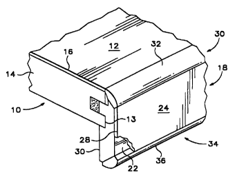
FIG. 1 is a fragmentary perspective view of a
countertop embodying the subject invention.
2o FIGS. 2-8 are cross-sectional viewsl showing the
sequence of construction of the edge piece of the
countertop.
FIG. 9 is a cross-sectional view of another
embodiment of the invention.
FIG. 10 is a cross-sectional view of yet
another embodiment of the invention.
DETAILED DESCRIPTION OF A PREFERRED EMBODIMENT
Referring to FIG. 1 0! the drawings, the
3o countertop of the subject invention comprises a deck 10
having a horizontal finished upper surface 12 and an
unfinished vertical edge 13. In the drawings, the deck
is shown as an unfinished substrata 14 and the finished
upper surface is a sheet of laminate 16 which is
adhesively attached to the substrate. Countertops of
this type are cvmrnonly used on kitchen cabinets and
similar structures. However, the invention can also be
_ . _ _ . _ _ ....... . .. . .. ~ m.. ,.,.. "" ", ., ."


CA 02293141 1999-12-24
3
utilized with decks made from veneer covered wood or -
aimilar materials, such as is used on tables, desk: and
other furniture items. The unfinished vertical edge 13
is covered by an edge piece 18 having a first planer side
20 which abuts the finished deck edge 13, and a second
planer side 22 which is parallel with and opposed to the
first side 20. The second side 22 of the edge piece 18
has a finished face 24, which is the same as or
complimentary to the finished upper surface on the deck.
1o In the embodiment illustrated, the edge piece is an
unfinished substrate, and the finished face 24 is a strip
of laminate 28 which is adhesively attached to the second
side 22, however, the edge piece can also be veneer
covered wood or other similar material.
The upper intersection o~f the deck and the edge
piece contains a first corner element 30. The first '
corner element is attached, to the upper edge of the edge
piece and hac a curved finished surface 32 which fairs
into both the finished surface 12 of the deck and the
finished face 24 of the edge piece. Thus, the first
corner element eliminates the line which normally occurs
between adjoining perpendicularly exposed laminate or
veneer surfaces. A second corner element 34 is located
at the lower edge of the edge piece to provide symmetry.
The second corner oloment 34 has a curved surface 36
which fairs into the finished face 24 of the edge piece.
Referring to FIGS. 2-e, in a preferred
embodiment the edge piece 18 is made from an elongate
rectangularly cross-sectioned block 38 of substrate
3o material which has approximately the same height as the
desired edge piece but is somewhat thicker, FIG. 2. The
laminate strip 28 is attached to one side or the block 38
and diagonal cuts a0 are made in the upper and lower
edges of the laminate side of the block, FIGS. 3-4. In
the embodiment illustrated, the diagonal cuts are
v-shaped notches. The notch shown in FIG. 3 has an
included angle of 90' and the notch shown in FIG. 4 is


CA 02293141 1999-12-24
4
cut so that the portion of the cut that extends across
the laminate strip 28 is substantially horisontal. The
notches 4o are cut such that their apices ate located at
the intersection of the block 38 and laminate 28. If
desired, the tuts in the block 38 and laminate strip can
be made before the laminate strip ie attached to the
block. This technique works best for the embodiment
shown in FIG. 4 but will work for the embodiment shown in
FTG. 3 also.
Rectangular strips 42, of a surface material,
which can be cut with a shaper, are placed in tha notches
4o and secured to the block by means such a: glue. The
preferred material for the strips, when they are used
with a laminate suzface desk, is a solid surfac~ thermo-
plastic material of the type sold under the trademark
CORIAN. The strips 42 are slightly larg~r in crose-
section than the notches 4o and thus protrudes slightly
above the front and ends of th~ bleak 38. Next, an
arcuate surface is cut on the strips 42 with a shaper in
2o a manner such that they fair into the laminate strip 28
on the front of the bleak 38, but still projects slightly
from its ends, FIG. 6.
Finally, the backside of the block and the
overhanging portions of the strip are cut with a router .
z5 to form a finished end piece 18 that mates with the deck,
thus forming the first corner element 30, FIG. 6_ In a
preferred embodiment, shown in FIGS. 1, 7 and 8, one side
of a tongue-and-groove joint 46 is form~d in the backside
of the block 38, with the height between the edge of the
30 first corner ~lement 30 and the tongue-and-groove joint
46 being a predetermined distance "h". The matching aide
of the tongue-and-groove joint can then be cut in the
edge 13 of the deok substrata 14 with the distance
between the top of the laminate sheet 16 and tongue-and-
35 groove joint being equal to the distance "h". This
permits the edge piece to me made in advance and then
installed on a deck on sit~, and still have a smoothly


CA 02293141 1999-12-24
faired surface betwoQn the deck laminate 16 and the first
corner element 30. With this embodiment, the back of the
block is cut to provide a glue slot 48 so that excess
amounts of the glue 44 used to attach the edge piece to
5 the deck will not be Squeezed out onto the fialshed
surfaces. If desired, the tongue-arid-groove joint can be
~liminated and the edge piwce can be flush mounted on the
deck as shown in FIG. 9.
In an alternate embodiment of the invention,
to shown in FIG. 10, the second corer element is not used
and the laminate strip Z8 extends to the bottom of the
edge piece 18. While this embodiment is shown without
the tongue-and-groove point, it can have the tongue-and-
groove joint also.
The terms and expressions which have been
employed in the foregoing specification are used therein
as terms of description and not of limitation, and there
is nc intention, in the use of such terms and exprQS-
sions, of excluding equivalents of the featuraS shown and
z0 described or portions thereof, it being recognized that
the scope of thB invention is defined and iimited only by
the claims which follow.

Representative Drawing
A single figure which represents the drawing illustrating the invention.
Administrative Status

For a clearer understanding of the status of the application/patent presented on this page, the site Disclaimer , as well as the definitions for Patent , Administrative Status , Maintenance Fee  and Payment History  should be consulted.

Administrative Status

Title Date
Forecasted Issue Date 2002-12-03
(22) Filed 1999-12-24
Examination Requested 1999-12-24
(41) Open to Public Inspection 2001-06-24
(45) Issued 2002-12-03
Deemed Expired 2014-12-24

Abandonment History

There is no abandonment history.

Payment History

Fee Type Anniversary Year Due Date Amount Paid Paid Date
Request for Examination $200.00 1999-12-24
Application Fee $150.00 1999-12-24
Maintenance Fee - Application - New Act 2 2001-12-24 $100.00 2001-12-05
Final Fee $150.00 2002-09-13
Maintenance Fee - Patent - New Act 3 2002-12-24 $50.00 2002-12-09
Maintenance Fee - Patent - New Act 4 2003-12-24 $50.00 2003-12-03
Maintenance Fee - Patent - New Act 5 2004-12-24 $100.00 2004-10-26
Maintenance Fee - Patent - New Act 6 2005-12-26 $100.00 2005-11-30
Maintenance Fee - Patent - New Act 7 2006-12-25 $100.00 2006-12-08
Maintenance Fee - Patent - New Act 8 2007-12-24 $100.00 2007-12-06
Maintenance Fee - Patent - New Act 9 2008-12-24 $100.00 2008-12-23
Maintenance Fee - Patent - New Act 10 2009-12-24 $125.00 2009-12-09
Maintenance Fee - Patent - New Act 11 2010-12-24 $325.00 2011-01-26
Maintenance Fee - Patent - New Act 12 2011-12-28 $125.00 2011-12-15
Maintenance Fee - Patent - New Act 13 2012-12-24 $125.00 2012-12-21
Owners on Record

Note: Records showing the ownership history in alphabetical order.

Current Owners on Record
KELLEY, BASIL T.
Past Owners on Record
None
Past Owners that do not appear in the "Owners on Record" listing will appear in other documentation within the application.
Documents

To view selected files, please enter reCAPTCHA code :


To view images, click a link in the Document Description column. To download the documents, select one or more checkboxes in the first column and then click the "Download Selected in PDF format (Zip Archive)" or the "Download Selected as Single PDF" button.

List of published and non-published patent-specific documents on the CPD .

If you have any difficulty accessing content, you can call the Client Service Centre at 1-866-997-1936 or send them an e-mail at CIPO Client Service Centre.


Document
Description 
Date
(yyyy-mm-dd) 
Number of pages   Size of Image (KB) 
Cover Page 2002-10-30 1 42
Cover Page 2001-06-22 1 39
Representative Drawing 2001-06-22 1 9
Abstract 1999-12-24 1 28
Description 1999-12-24 5 213
Claims 1999-12-24 3 67
Drawings 1999-12-24 2 53
Correspondence 2002-09-13 2 72
Assignment 1999-12-24 2 86
Correspondence 2004-11-10 1 21
Fees 2004-10-26 1 40
Correspondence 2004-10-21 1 27
Fees 2005-11-30 1 24
Fees 2006-12-08 1 25
Fees 2007-12-06 1 25
Fees 2008-12-23 1 28
Fees 2009-12-09 1 200
Fees 2011-01-07 2 48
Fees 2011-01-26 1 22
Fees 2011-12-15 1 24
Fees 2012-12-21 1 24