Note: Descriptions are shown in the official language in which they were submitted.
CA 02293594 1999-12-02
WO 98/5573() YCT/AU98/00421
-1
Title
RETRIEVAL HEAD FOR A DRILL BIT COMPOSED OF
A PLURALITY OF BIT SEGMENTS
Field of the Invention
This invention relates to a retrieval head for use in conjunction with a down
hole tool
for in situ retrieval of a drill bit composed of a plurality of bit segments.
Background to the Invention
A system for in situ replacement of a drill bit for a ground drill is
described in
Applicant's International Application No PCT/AU94l00322 (WO 94/29567), the
contents of which is incorporated herein by way of reference. The system in WO
94/29567 comprises a drive sub which is adapted for connection to a lower end
of a
core barrel attached to a drill pipe; a core drill bit composed of a plurality
of separate
bit segments; a bit locking sleeve for selectively locking the bit segments
onto seats
provided about an inner surface of the drive sub and subsequently releasing
the bit
segments from those seats; and, a down hole tool for operating the bit locking
sleeve
and installing and retrieving the drill bit segments.
A slidable cradle extends from a lower end of the down hole tool for carrying
the bit
segments to and from the drive sub. When installing the bit segments, the
cradle is
extended from a lower end of the tool against the bias of a spring. Bit
segments are
then held by elastic bands about the cradle with one end abutting a stop
provided at a
distant end of the cradle and an opposite end of each segment bearing against
a head
of the down hole tool. When the down hole tool is lowered into the ground
drill and
reaches a predetermined position within the drive sub, the cradle is retracted
into the
main body of the tool by the spring. This causes an upper end of the bit
segments to
slide along the head of the tool so as to extend laterally of the periphery of
the tool.
The bit locking sleeve is simultaneously pushed by the tool so as to catch the
ends
of, and move inside, the bit segments thereby expanding the bit segments to
the inner
diameter of the drive sub and locking the bit segments into a cutting
position.
CA 02293594 1999-12-02
WO 98/55730 PCT/AU98/00421
-2-
When it is necessary to change the core bit and thus retrieve the bit
segments, the
tool is again lowered into the drill pipe and drive sub with the cradle locked
into the
extended position. At a predetermined position, the down hole tool engages the
bit
locking sleeve at which time the cradle extends from the lower end of the
drive sub.
The down hole tool is then pulled upwards a short distance. This pulls the bit
locking sleeve upwards thereby releasing the bit segments from the seats on
the drive
sub. The bit segments collapse onto the cradle by action of the elastic band.
Upon
further upward pulling of the down hole tool, the tool releases itself from
the bit
locking sleeve and can thus be pulled to the surface with the bit segments.
Field trials of the above system have proved very successful. However, it is
believed
that one possible source of failure of the system is that when the bit
segments are
released so as to collapse back onto the cradle there is a remote but
nevertheless
existent possibility that they can jam in the drive sub and in particular with
the bit
locking sleeve. This can arise because when the bit segments are released and
commence to collapse onto the cradle, they pivot or tilt radially inwardly
from the
lower end of the bit segments with increasing angle until the bit locking
sleeve is
pulled completely away from the bit segments. If the tool is withdrawn very
quickly
so that the uppermost end of the bit segments have not had sufficient time to
fully
collapse onto the cradle, perhaps due to the viscous nature of the fluid
within which
the drill is operating, the upper end of the bit segments can jam with the
lower end
of the bit locking sleeve.
Summary of the Invention
It is an object of the present invention to provide a retrieval head adapted
for use
with a down hole tool which will substantially eliminate any possibility of
jamming
of the bit fingers during the retrieval process.
According to the present invention there is provided a retrieval head for
coupling to a
down hole tool for retrieving a drill bit composed of a plurality of bit
segments, the
down hole tool adapted to travel through a drill string and a drive sub
attached to the
CA 02293594 1999-12-02
WO 98155730 PCT/AU98/titi421
-3-
drill string, the tool further adapted to release bit segments clamped between
the
drive sub and a bit locking sleeve held within the drive sub so that the bit
segments
can collapse onto the retrieval head, the retrieval head including:
a body having a first length and a contiguous second length, the first length
being of a first constant diameter and the second length having a portion of
reduced diameter relative to the first diameter; the first diameter being
dimensioned so that the bit segments can initially collapse radially inwardly
wholly onto an outer circumferential surface of the first length; and, the
reduced diameter portion being dimensioned so that when the bit segments are
arranged about the reduced diameter portion, the bit segments can pass
through the drive sub, bit locking sleeve and drill string; whereby, in use,
when bit segments clamped to the drive sub are collapsed onto the first length
and the down hole tool, to which the retrieval head is coupled, is pulled
upwardly, the bit segments slide relative to and along the retrieval head from
I S the first length by abutment of the bit segments with the drive sub andlor
bit
locking sleeve to the reduced diameter portion where the bit segments
together with the retrieval head can pass through the bit locking sleeve and
drill string to be retrieved by said down hole tool.
Preferably the reduced diameter portion includes a first part of progressively
decreasing diameter contiguous with the first length.
Preferably the first part comprises a first frustum contiguous with the first
length.
Preferably the reduced diameter portion includes a second part contiguous with
the
first part.
Preferably the second part includes a second frustum contiguous with the first
frustum and having a diameter which reduces at a greater rate than that of the
first
frustum.
CA 02293594 1999-12-02
WO 98/55 r 30 PCT/A l; X8/00421
-4-
Preferably said retrieval head further includes a stop coupled to an end of
said
second length distant said first length against which said bit segments can
abut to
prevent said segments from falling off said retrieval head.
Preferably said retrieval head further includes centering means provided on
the outer
circumferential surface of the rust length for substantially centering the
retrieval head
within the drill string, drive sub and bit locking sleeve.
Preferably said centering means comprises a plurality of raised ridges running
longitudinally of said first length and spaced about the circumference of said
first
length.
Preferably said ridges are spaced by a distance to receive a single bit
segment.
Preferably opposite ends of said ridges progressively taper in height to the
level of
said outer circumferential surface of said first length.
Preferably said retrieval head further includes magnetic means disposed along
a
portion of said first and second lengths for attracting bit segments upon
release from
said drive sub and holding said bit segments to said retrieval head.
Preferably said retrieval head comprises a central core extending along said
first and
second lengths for housing said magnetic means, and sleeve means of non-
magnetic
material for covering said core.
Preferably said sleeve means comprises a first sleeve part for covering said
first
length and a separate second sleeve part for covering said second length.
Preferably said retrieval head is further provided with means for releasably
coupling
said retrieval head to a down hole tool.
_____..___. __T .___ .__.____.___.._.__. __. . _ _
CA 02293594 1999-12-02
WO 98/55730 PCT/AU98/00421
_j_
Brief Description of the Drawing
An embodiment of the present invention will now be described by way of example
only, with reference to the accompanying drawings in which:
Figure 1 is an isometric view of an embodiment of the retrieval head
in accordance with the present invention;
Figure 2 is a longitudinal section view of the retrieval head shown in
Figure 1;
Figure 3 is an end view of the retrieval head shown in Figures 1 and
2;
Figure 4 is an exploded view of the retrieval head shown in Figures 1
and 2;
Figure 5 is a representation of a prior art retrieval head; and,
Figures 6A-6C are schematic representations of the retrieval head when in
use retrieving bit segments from a drill string.
Detailed Description of the Preferred Embodiment
The retrieval head 10 shown in the accompanying drawings is typically used in
a
system for in situ replacement of drill bit segments of a core drill of the
type
described in the afore-referenced WO 94/29567. In that system, a part of which
is
depicted in Figure 5, a running tool 11 is used to transport bit segments to
and from
a drive sub 12. The tool 11 includes a cradle 13 onto which the bit segments
14 are
loaded when transported to and from the drive sub. The cradle 13 in essence
comprises a bar or shank of constant diameter with an enlarged head 15 at its
lowermost end. The same cradle 13 is used for both retrieval and installation
of the
CA 02293594 1999-12-02
WO 98/55730 PCT/AU98/00421
_6_
bit segments 14. The bit segments 14 are held in place by a bit locking sleeve
16
which is slid up and down the drive sub by the down hole tool. Figure 6A
depicts
the bottom end of a core drill of the type described in the above-referenced
document
immediately prior to retrieval of the bit segments. The bit segments 14 are
clamped
by the bit locking sleeve 16 to the drive sub 12. Elastic band 18 extends
about the
bit segments 14 and is retained within a cavity or recess formed between the
bit
segments 14 and an inner circumferential surface of the drive sub 12. The down
hole tool 11 is lowered through a drill string (not shown) into the drive sub
12 to a
point where it engages the bit locking sleeve 16. A down hole tool 11 is then
pulled
upwardly a short distance. This pulls the bit locking sleeve 16 upwardly
thereby
releasing the bit segments 14 which are free to collapse onto the cradle 13 of
the
down hole tool 11 by virtue of the compression of elastic band 18.
It will be recognised that as the bit locking sleeve 16 is pulled upwardly the
segments 14 pivot radially inwardly. The pivoting motion effectively ceases
when
the lowermost end 20 of the segments 14 abut the cradle 13 on the down hole
tool
11. The cradle 13 on the down hole tool is of relatively small diameter and
therefore
the angle of pivoting is relatively large.
If the down hole tool is retracted too quickly, upper ends 22 of the bit
fingers may
not have sufficient time to locate against the body of the tool and/or cradle.
Therefore the upper ends 22 may get caught on lower end 24 of the bit locking
sleeve 16 or indeed on other components (such as a landing ring) within the
drill
string. Figure 5 enclosed depicts how this may happen in the prior art.
The present retrieval head 10 was developed to alleviate the possibility of
the bit
segments jamming when being retrieved. The retrieval head 10 is adapted for
connection to a down hole tool of the type described in the above-mentioned
reference in place of the described cradle.
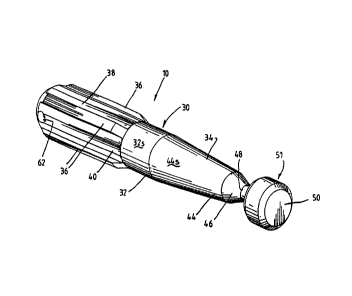
Referring to Figures 1 to 4, it can be seen that the retrieval head 10
comprises a
body 30 having a first length 32 and contiguous second length 34. The first
length
__. __-._...___._.____ T _..~~._..._...
CA 02293594 1999-12-02
WO 98/55730 PCT/AU98/0042I
32 is of substantially constant diameter. Four raised ridges 36 run
longitudinally
along an upper portion of the first length 32. The ridges 36 are evenly spaced
about
outer circumferential surface 38 of the first length 32 and taper at their
opposite ends
down to the surface 38. Because the ridges 36 are formed by milling, a pair of
flats
40 extend parallel to and on opposite sides of each ridge 36. However, the
flats 40
are of no particular significance and simply arise due to the manufacturing
process.
'the second length 34 has a portion 42 of reduced diameter relative to that of
the first
length 32. Indeed, the portion 42 is composed of several separate sections of
lengths
of differing diameter. Specifically, there is a first frustum 44 which is
contiguous
with the first length 32 and is of progressively reducing diameter. Contiguous
with
the first frustum 44 is a second frustum 46 which has a diameter which
decreases at
a greater rate than that of the first frustum 44. Contiguous with the second
frustum
46 is a part 48 of constant diameter. The part 48 terminates with a bulbous
stop 50
of a diameter in the order of that of the first part 32. As shown in Figures 2
and 4,
the second frustum 46, constant diameter part 48 and stop 50 are formed as a
single
integral unit 51 separate from the first frustum 34 although together they
comprise
the second length 34.
As shown in Figures 2 and 4, the retrieval head 10 includes a central core 52.
The
core 52 is covered by a two part sleeve comprising frusto-conical sleeve 44S
which
sits on an upper frusto-conical shaped length of the central core 52 which in
part
forms the second length 34, and a tubular sleeve 32S which covers a first
length 32.
A lower end of the core 52 is provided with a threaded stud 54 which
threadingly
engages the unit 51. This effectively locks the sleeve 445 onto the central
core 52.
A reduced diameter portion 56 at a upper end of the core 52 is also provided
with an
internal threaded cavity 58 for coupling to the down hole tool used to
transport the
retrieval head 10 to the drive sub 12 for installing and retrieving bit
segments 14. A
transverse hole 60 is also provided in the reduced diameter portion 56 for
registration
with a similar hole 62 formed in the sleeve 325. A threaded stud or other
mechanical
fastener (not shown) passes through holes 62 and 60 to lock the shell 32S onto
the
core 52.
CA 02293594 1999-12-02
WO 98/55730 YCT/AU98/00421
The core S2 is provided with an internal cavity 64 and four longitudinally
extending
slots 66 which provide access to the cavity 64. Magnetic means 68 in the form
of
magnets 70 and rectangular bar 72 are housed within the cavity 64 and slots
66.
Specifically, a series of rectangular rare earth magnets are initially built
up on to
opposite sides of the rectangular bar 72. Because the second part 34 of the
head 10
is of reducing diameter, the number of magnets 70 stacked upon each other
reduces
along the length of the bar 72. Once the magnets 70 have been built up upon
opposite sides of the bar 72 that sub-assembly is installed in the core 52
with the bar
72 located in the recess 64 and the magnets 70 in the opposing slots 66. To
complete the magnetic means 68, magnets 70 are now built up upon the opposing
free faces of the bar 72 through the open available slots 66.
The core 52, as well as sleeves 32s, 44s, and are made from non-magnetic
material
such as aluminium.
The operation of the retrieval head 10 will now be described with particular
references to Figures 6A-6C. Figure 6A shows the configuration of the drive
sub 12,
bit segments 14, and bit locking sleeve 16 prior to retrieval of the bit
segments 14.
The retrieval head 10 is fastened to the lowermost end of a down hole tool 74
and
lowered through the drill string to the drive sub 12 to a point where
substantially the
whole length of the retrieval head 10 extends beyond the lowermost end of the
drive
sub I2. The tool 74 is then drawn upwardly a short distance as shown in Figure
6B.
In doing so, latch dogs (not shown) on the tool 74 engage the bit locking
sleeve 16
and pull the locking sleeve upwardly so as to release the bit segments 14.
This
upward movement also results in the first length 32 of the head 10 being drawn
within the drive sub 12 (as shown in Figure 6B). With the bit locking sleeve
16
pulled out of the way, the action of the elastic band 18 assists in collapsing
the bit
segments 14 onto the first length 32. To further assist in releasing the
segments 14
from the drive sub 12, elastomeric pads 76 can be adhered to a face of the bit
segments 14 which would normally contact the inner surface of the drive sub
12.
Further, the magnets 70 held within the core 52 of the tool 10 also attract
the
segments 14 to the head 10 and indeed are of sufficient strength so as to hold
the
.. ..._._....,...r_.~.~.. . ........ ..............~,~..__. _
__........_..._.~......_..........._........ ........__..._,~.__....__.....__.
CA 02293594 1999-12-02
WO 98/55730 PCT/AU98/00421
-9-
segments 14 onto the head 10 in the absence of the elastic band 18. This is
advantageous in the occurrence of a failure in the band 18, for example due to
breakage or melting.
As seen in Figure 6B when the segments 14 collapse onto the first length 32,
their
lowermost end or crown 20 may still abut the lowermost end of the drive sub
12. As
the tool 74 is pulled further upwardly, the abutment of the segments 14 on the
drive
sub 12 results in the head 10 sliding inside the segments 14. As this sliding
motion
continues, the segments 14 are moved radially inwardly due to the reducing
diameter
of the second length 34 and in particular due to the tapering nature of the
frustums
44 and 46. Eventually, the segments 14 are located about a portion on the
second
length 34 at which they can pass wholly through the drive sub 12 as shown in
Figure
6C. In order to be wholly retrieved, the segments 14 and head 10 must also
pass
through the bit locking sleeve 16 which is disposed higher up in the drive sub
12. If
any part of the segments 14 abut the bit locking sleeve 16 on the upward
movement
of the tool 74, then the head 10 will again simply slide inside the segments
14 to a
position where the segments 14 can then pass through the bit locking sleeve
16. A
similar action will occur if the segments 14 contact any other internal
component in
the ground drill when the tool 74 is being withdrawn. For example if the
segments
14 come into contact with a landing ring typically used in core drilling
systems.
The stop 50 provides an abutment surface to prevent the segments 14 from
falling off
the end of the head 10. The constant diameter part 48 is dimensioned so that
if the
segments 14 slide relative to the head 10 to the position where the segments
14 abut
the stop 50, the radially outermost portions of the crowns 20 do not extend
beyond
the radius of the stop 50.
The ridges 36 assist in maintaining the head 10 in a centralised position
through the
drive sub 12 and associated drill string (not shown). Thus, while the magnets
70 will
cause the head 10 to tend to be attracted to one side of the drill string and
thus tend
to skew the head and perhaps the tool 74, the ridges 36 substantially limit
the
skewing of the head 10. The tapered opposite ends of each ridge 36 also ensure
that
CA 02293594 1999-12-02
WO 98i~5730 PCTi.4U98/00421
_ 10_
the ridges 36 do not become locked on any internal component of the drill.
Further,
the ridges 36 are spaced by a distance so that a single bit 14 can be disposed
therebetween when initially released from the drive sub 12.
From the above description of the preferred embodiment, it is clear that the
retrieval
head 10 enjoys numerous advantages and benefits over the prior art system for
retrieving bit segments 14. Significantly, because of the relative diameters
of the
first and second lengths 32 and 34, when the bit segments 14 are first
released, they
need travel only a short distance to contact the surface of the first length
32. As
such, the degree of pivoting or tilting of the segments 14 is minimised in
comparison
to that in the prior art. Indeed, due to the configuration of the segments 14,
the
angle of pivot is actually in an opposite sense to that in the prior art. This
substantially avoids the possibility of the upper ends 22 of the bit segments
14
catching in the bit locking sleeve 16 or other components of the drill when
being
withdrawn. Also, the segments 14 are able to slide along the body of the head
10, to
a position in which they can pass through any typical constriction within the
ground
drill. The magnets 70 assist in holding the segments 14 to the head 10 in the
event
that the bands 18 break or melt.
Now that an embodiment of the present invention has been described in detail,
it will
also be apparent to those skilled in the relevant arts that numerous
modifications and
variations may be made without departing from the basic inventive concepts.
For
example, the sleeve 44S and unit S 1 are shown as separate components.
However,
they can be manufactured as an integral unit. Also, the magnetic means 68 is
shown
as being essentially built up from a rectangular bar and a plurality of small
magnets
however any suitable form of magnetic assembly, be it one piece or made from
separate components, can be used. All such modifications and variations are
deemed
to be within the scope of the present invention the nature of which is to be
determined from the foregoing description and the appended claims.
1 ._ ..~......_ ..___..... ._.. _ _. _ . _.__. _,_ .... .._._._W _.___
.._..__~___~_.. .__._~ ~..~