Language selection

Search

Patent 2293639 Summary

Third-party information liability

Some of the information on this Web page has been provided by external sources. The Government of Canada is not responsible for the accuracy, reliability or currency of the information supplied by external sources. Users wishing to rely upon this information should consult directly with the source of the information. Content provided by external sources is not subject to official languages, privacy and accessibility requirements.

Claims and Abstract availability

Any discrepancies in the text and image of the Claims and Abstract are due to differing posting times. Text of the Claims and Abstract are posted:

  • At the time the application is open to public inspection;
  • At the time of issue of the patent (grant).
(12) Patent: (11) CA 2293639
(54) English Title: TRANSFER AND CENTERING SYSTEM FOR CONTACT LENSES
(54) French Title: SYSTEME DE TRANSFERT ET DE CENTRAGE POUR LENTILLES DE CONTACT
Status: Deemed expired
Bibliographic Data
(51) International Patent Classification (IPC):
  • B29C 31/00 (2006.01)
  • B29D 11/00 (2006.01)
(72) Inventors :
  • DOBNER, MICHAEL H. (United States of America)
(73) Owners :
  • BAUSCH & LOMB INCORPORATED (United States of America)
(71) Applicants :
  • BAUSCH & LOMB INCORPORATED (United States of America)
(74) Agent: OSLER, HOSKIN & HARCOURT LLP
(74) Associate agent:
(45) Issued: 2003-09-16
(86) PCT Filing Date: 1998-06-11
(87) Open to Public Inspection: 1998-12-23
Examination requested: 1999-12-07
Availability of licence: N/A
(25) Language of filing: English

Patent Cooperation Treaty (PCT): Yes
(86) PCT Filing Number: PCT/US1998/012444
(87) International Publication Number: WO1998/057788
(85) National Entry: 1999-12-07

(30) Application Priority Data:
Application No. Country/Territory Date
60/050,158 United States of America 1997-06-19

Abstracts

English Abstract


A method for transferring a lens-shaped article (23) from a first support (25)
to a centered position on a second support (31) employs a transfer tool (1)
having a slideable plunger (11) and plunger sleeve (21) that cooperates with
the first and second support to ensure that the article is oriented in a
desired manner when transferred.


French Abstract

L'invention concerne un procédé de transfert d'un article en forme de lentille (23) depuis un premier support (25) vers une position centrée, sur un second support (31), au moyen d'un outil de transfert (1) pourvu d'un piston coulissant (11) et d'un manchon (21) de piston, qui coopèrent avec le premier et le second supports afin de s'assurer que ledit article est convenablement orienté au moment de son transfert.

Claims

Note: Claims are shown in the official language in which they were submitted.


1. An apparatus (1) for transferring a lens-shaped article (23) from a first
support (25) to a centered position on a second support (31), wherein said
lens-shaped
article includes a concave surface and a convex surface, the first support
includes a
support surface for supporting the convex surface of the article and the
second support
includes a receiving surface for receiving the convex surface of the article,
said apparatus
comprising:
(a) a plunger (11) comprising an elongated body, a tip (12) at a lower end of
the
elongated body that includes a contacting surface, and a conduit (18)
extending through
the elongated body, said conduit connected to a vacuum source and terminating
at an
opening in the contacting surface of the tip; and
(b) a sleeve (21) surrounding the elongated body of the plunger, said plunger
and
sleeve being slideable with respect to each other, wherein the second support
includes a
portion having an outer diameter generally corresponding to an inner diameter
of the
plunger sleeve.
2. The apparatus of claim 1, wherein the first support includes a ring-like
member (27) extending above the support surface that has an inner diameter
generally
corresponding to an outer diameter of the plunger body.
3. The apparatus of claim 1, wherein the first support includes a concave
support surface that generally corresponds in shape to the convex surface of
the
lens-shaped article.
4. The apparatus of claim 3, wherein the first support includes a mold
member in which the lens-shaped article was cast, such that the lens-shaped
article is
supported on a concave molding surface of the mold member and the ring-like
member
extends above and is centered with respect to the molding surface.
5. The apparatus of claim 1, wherein the second support includes a spindle
arbor, such that the lens-shaped article is received on a receiving surface at
an end of the
-6-


arbor, and an outer diameter of the arbor body generally corresponds to the
inner
diameter of the plunger sleeve.
6. The apparatus of claim 5, wherein the receiving surface at the end of the
arbor includes an O-ring (33) for contacting the convex surface of the
article.
7. The apparatus of claim 5, wherein the arbor receiving surface has an
opening therein connected to an arbor vacuum source (35).
8. The apparatus of claim 1, wherein the tip contacting surface includes an
O-ring (19) for contacting the concave surface of the article.
9. The apparatus of claim 1, wherein the plunger is moveable with respect to
the sleeve between a retracted position and an extended position.
10. The apparatus of claim 1, wherein the lens-shaped article is a contact
lens.
11. A method of transferring a lens-shaped article from a first support to a
centered position on a second support, said lens-shaped article including a
concave
surface and a convex surface, the first support including a support surface
for supporting
the convex surface of the article, and the second support including a
receiving surface for
receiving the convex surface of the article, said method comprising:
a) removing the article from the first support with a transfer tool, the
transfer tool
comprising a plunger comprising an elongated body, a tip at a lower end of the
elongated
body that includes a contacting surface, a conduit extending through the
elongated body,
said conduit connected to a vacuum source and terminating at an opening in the
contacting surface of the tip, and a sleeve surrounding the elongated body of
the plunger,
the sleeve and plunger being slideable with respect to each other, said first
support
having a ring-like member (27), said ring-like member extending above said
first support
and having an inner circumference corresponding to an outer circumference of
said
plunger, said first support centered with respect to the ring-like member
(27);

-7-


wherein the article is removed from the first support by inserting the plunger
body into the ring-like member to position the tip near the concave article
surface while
the plunger is in an extended position with respect to the sleeve, with said
article
centered on said first support, and activating the vacuum source of the
transfer tool, said
article centering on said plunger when said plunger is inserted into the ring-
like member;
and
(b) transferring the article to a centered position on the second support
receiving
surface, by moving the plunder to a retracted position with respect to the
sleeve, placing
the sleeve over a portion of the second support having an outer diameter
generally
corresponding to an inner diameter of the sleeve, and contacting the convex
article
surface with the receiving surface and inactivating the vacuum source of the
transfer tool.
12. The method of claim 11, wherein the first support includes a mold
member in which the lens-shaped article was cast, such that the lens-shaped
article is
supported on a concave molding surface of the mold member, and the ring-like
member
extends above and is centered with respect to the molding surface.
13. The method of claim 11, wherein the second support includes a spindle
arbor, such that the lens-shaped article is received on a receiving surface at
an end of the
arbor, an outer diameter of the arbor body generally corresponding to the
inner diameter
of the plunger sleeve, and wherein the method includes placing the sleeve over
the arbor
body to contact the anterior article surface with an end of the arbor.
14. The method of claim 13, wherein the arbor receiving surface includes an
O-ring for contacting the convex surface of the article.
15. The method of claim 13, wherein the arbor receiving surface has an
opening therein connected to an arbor vacuum source, and wherein the method
includes
activating the arbor vacuum source when the convex article surface is in
contact with the
arbor receiving surface.
-8-


16. The method of claim 11, wherein the lens-shaped article is a contact lens.
17. A method of transferring a contact lens, a convex surface of said contact
lens supported by and centered with respect to a concave support surface of a
first
support, said method comprising:
a) transferring the contact lens from the first support to a transfer tool,
the transfer
tool comprising a plunger comprising an elongated body, a tip at a lower end
of the
elongated body that has an opening connected to a vacuum source, and a sleeve
surrounding the plunger body, said first support having a ring-like member
(27), said
ring-like member extending above said first support and having an inner
circumference
corresponding to an outer circumference of said plunger, said first support
centered with
respect to the ring-like member (27);
wherein a concave surface of the contact lens is contacted with the transfer
tool tip by
inserting the plunger body into the ring-like member, while the plunger is in
an extended
position with respect to the sleeve, with said contact lens centered on said
first support,
and the vacuum source is activated, said contact lens centering on said
plunger when said
plunger is inserted into the ring-like member; and
(b) transferring the contact lens centered on said transfer tool to a second
support, said second support having an outside diameter corresponding to an
inner
diameter of said sleeve, said sleeve sliding over said second support, said
contact lens
centered on a receiving surface of said second support, inactivating said
vacuum of said
transfer tool, wherein the convex contact lens surface is contacted with said
receiving
surface on the second support while the plunger is in a retracted position
with respect to
the sleeve.
18. The method of claim 17, wherein step (b) further comprises activating a
vacuum source connected to the second support receiving surface.
-9-

Description

Note: Descriptions are shown in the official language in which they were submitted.


CA 02293639 1999-12-07
__ _
- ~
_ ~ n eee ~ec
- , a s v v
~s " W w
T SFER AuID CENTERING SYSTEM FOR CONTACT LENSES
BACKGROUND OF THE INVENTION
The present invention relates to a method and apparatus for transferring a
lens-
~ed article between different stages of a manufacturing process, while
ensuring that
article remains centered during the transfer. The invention is especially
useful for
~ferring contact lenses.
Small, delicate work pieces such as contact lenses are difficult to transfer
through
multiple stages of a manufacturing process. This is especially true if it is
desired to
maintain the contact lens in a desired orientation, such as in a centered
position during
the manufacturing process. Even though automated processes minimize human
contact
with the lenses thus reducing the chance of human error, the challenge is
designing
processes that ensure that the lens is properly oriented when transferred
beriveen stages.
Early prior art methods for transferring contact lenses between stakes were
essentially performed manually. This included placement of the lens into the
final
packaging. More recently, transferring methods have been automated, some
including
robotics. For example, U.S. Patent No. 5,561,970 (Edie et al) discloses a
robotic method
of transferring a contact lens from a hydration cup into a packaging
container, such as a
blister package. It is not critical in this method that the contact lens be
centered in
relation to the transfer tool, hydration cup or to the package.
SUMMARY OF THE INVENTION
The invention provides a method for transferring a lens-shaped article from a
first
support to a centered position on a second support. The invention provides a
reliable
mechanism for ensuring that the article remains centered during the transfer
between
manufacturing stages, either for fully automated manufacturing stages or
manufacturing
stages assisted with an operator. Additionally, the invention provides an
apparatus for
carrying out the various preferred embodiments.
The method of this invention involves removing the lens-shaped article from
the
first support with a transfer tool such that the article is centered with
respect to the
AMENDED SHEET


CA 02293639 1999-12-07
., ., . .
, . .
. " .. ~.
transfer tool, and transferring the article to a centered position on the
second support
receiving surface. 'The transfer tool comprises a plunger comprising an
elongated body, a
tip at a lower end of the elongated body that includes a contacting surface, a
conduit
extending through the elongated body that is connected to a vacuum source and
terminating at an opening in the contacting surface of the tip, and a sleeve
surrounding
the elongated body of the plunder, the sleeve and plunger being slideable with
respect to
each other.
-1.1-
AMENDED SHEET


CA 02293639 1999-12-07
WO 98/57788 PCT/US98/12444
The article is removed from the first support by moving the plunger to an
extended position with respect to the sleeve, positioning the tip near the
concave article
surface, and activating the vacuum source of the transfer tool. The article is
transferred
to a centered position on the second support receiving surface by moving the
plunger to a
retracted position with respect to the sleeve, placing the sleeve over a
portion of the
second support having an outer diameter generally corresponding to an inner
diameter of
the sleeve, and contacting the convex article surface with the receiving
surface and
inactivating the vacuum source of the transfer tool.
BRIEF DESCRIPTION OF THE DRAWINGS
FIG. 1 is a schematic perspective view of a transfer tool according to various
preferred
embodiments;
FIG. 2 is an exploded view of the transfer tool of FIG. 1;
FIG. 3 is a partial cross-sectional view of the transfer tool with the plunger
in an
extended position; and
FIG. 4 is a partial cross-sectional view of this transfer tool with the
plunger in a retracted
position.
DETAILED DESCRIPTION OF PREFERRED EMBODIMENTS
Refernng now to the drawings, there is seen in the various Figures a transfer
and
centering tool 1 which is used to transfer a lens-shaped article 23 from a
first support to a
centered position on a second support.
For the described illustrative embodiment, contact lens 23 is initially
supported
on and retained in mold 25, mold 25 being part of a mold assembly in which the
lens was
cast. For this embodiment, mold 25 and lens 23 are retained in a fixture
designed for
holding the rsaold/lens combination and for releasing the contact lens from
the mold. The
second support is part of an edging apparatus having a spindle arbor that
holds the lens
during the ~e~l frog operation. However, it is understood that the transfer
tool of this
invention may be employed with other types of equipment employed in various
lens
manufacturing processes where it is desired to transfer the lens between
substations while
ensuring the lens is oriented in a desired, predetermined manner.
-2-


CA 02293639 1999-12-07
WO 98/57788 PCTIUS98/12444
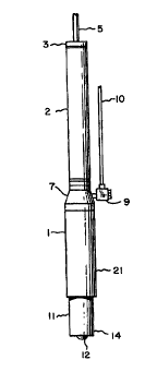
As seen in FIGS. 1 and 2, transfer tool 1 includes plunger 11 and plunger
sleeve
21. Plunger 11 and plunger sleeve 21 are slideable with respect to each other,
more
specifically, plunger 11 is movable between an extended position and a
retracted position
with respect to plunger sleeve 21 by means of a plunger actuator. (In FIG. 1,
plunger 11
is in an extended position.) For the illustrated embodiment, the plunger
actuator is a
conventional spring-biased return air cylinder 2 having actuating rod 6, rod 6
extending
and retracting to provide a stroke. Actuator 2 may be attached via connector 3
to tubing
5, and attached to plunger sleeve 21 via cylinder adapter 7. Tubing 5 leads to
a
pressurized air source for activating air cylinder 2. Plunger 11 includes tip
12 at its lower
end for contacting the concave surface of the contact lens, as described in
more detail
below. The apparatus further includes tubing 10 leading to a vacuum source
which may
be attached to cylinder adapter 7 via fitting 9.
Referring to FIG. 2, for the described embodiment, the top end of air cylinder
2
may include female threads for connection to male threads on connector 3, and
the
bottom end of air cylinder 2 may include male threads for connection to female
threads
on cylinder adapter 7 (the threaded connections not being shown in the
drawings).
Connector 3 has an opening for receiving tubing 5 which, as mentioned, is
connected to a
pressurized air source. Cylinder adapter 7 includes lateral opening 8 for
connection to
fitting 9.
The lower end of rod 6 may be connected to plunger 11 via connection elements
such as spring washer 13, cylinder bushing 15, and retaining ring 17. For the
illustrated
embodiment, cylinder bushing 15 has a lateral groove 16 which, in conjunction
with
conduit 18 extending through the plunger elongated body, provides a conduit
for the
vacuum source to extend from tubing 10, through fitting 9 and plunger 11, to
an opening
from conduit 18 in tip 12. Bushing 15 is attached to rod 6, for example with a
threaded
connection. The internal retaining ring 17 locks into threads of plunger l l
to secure
bushing 1 S and washer 13, washer 13 permitting bushing 15 to float slightly
with respect
to plunger 11.
Plunger sleeve 21 may include female threads for connection to male threads on
connector 3; accordingly, when the apparatus is assembled as in FIG. 1, sleeve
21
-3-


CA 02293639 1999-12-07
WO 98/57788 PCT/US98/12444
surrounds plunger 11. For the described embodiment, sleeve 2 i remains in a
fixed
position with respect to connector 3 and adapter 7, while plunger 11 is
slideable between
extended and retracted positions by activation of rod 6.
The lower end of plunger 11 has tip 12, which preferably has the form of a
convex, domed surface with an opening formed in this surface from conduit 18.
An o-
ring 19 may be placed around tip 12, whereby the concave surface of a contact
lens 23
contacts tip 12 and o-ring 19 when it is contacted with plunger 11 (as seen in
FIG. 3).
This lower end of plunger 11 may include a small annulus 14 around it, to
facilitate
centering of the contact lens with respect to tip 12.
As mentioned, for the described embodiment, the contact lens is initially
supported on mold 25 in which it was molded. Mold 25 is retained in a fixture
for
mechanically releasing contact lens 23 adhered to mold 25. This fixture
includes a
support 28 for the bottom portion of mold 25 and shear ring 27. When shear
ring 27
applies pressure to mold 25 about the periphery of the contact lens to distort
mold 25, the
lens is mechanically released from the mold. As seen in FIG. 3, an upper
portion of
shear ring 27 extends above mold 25, and this ring-like member has an inner
circumference that generally corresponds to an outer circumference of plunger
11; since
mold 25 is centered with respect to shear ring 27 and lens 23 is centered with
respect to
mold 25, this ensures that plunger 11 is centered with respect to mold 25 (and
lens 23)
when it contacts the lens. This fixture may further include ring-like member
26 which
serves to facilitate an operator guiding the plunger into the shear ring. The
fixture may
further include conduit 29, extending through body 30, for introducing
pressurized air to
mold 25 around the periphery of lens 23, as described in more detail below.
The second support to which the lens is transferred may be an apparatus for
mechanically edging the lens, that includes arbor 31. Arbor 31 is mounted on a
spindle
shaft (not shoa~rn).
In operation, as illustrate ~ FIG. 3, plunger 11 is inserted into ring 27 of
the dry
release fixtur,~ ~w°ith plunger 11 c. :3ed beyond the plunger sleeve
2'he lens 23 is
mechanically released from the le>~ mold 25 and a puff of air is supplied via
conduit 29
to assist in lifting the lens from mold 25. The vacuum source connected via
tubing 10 is
-4-


CA 02293639 1999-12-07
WO 98/57788 PCT/US98/12444
activated so that a vacuum is created at the opening in tip 12 in contact with
the lens, and
the lens is then held onto the transfer tool plunger tip by maintaining the
vacuum until
' the lens is transferred to the next station. As mentioned, plunger 11 is
centered with
respect to mold 25 and lens 23 when its tip is contacted with lens 23, and
centering of the
lens with respect to tip 12 is further facilitated by constraining the lens in
the recess
formed by annulus 14 that is slightly larger than the lens outside diameter.
The transfer tool plunger 11 is then retracted inside the plunger sleeve 21.
With
the plunger retracted inside the plunger sleeve, sleeve 21 is slid over arbor
31, until it
stops against o-ring 33, such that the combination has the configuration shown
in FIG. 4.
The outside diameter of the portion of arbor 31 that receives sleeve 21
generally
corresponds to the inside diameter of sleeve 21. Accordingly, lens 23 is now
centered
with respect to arbor 31. For the described embodiment, arbor 31 further
includes
annulus 32 and o-rings 33 contained therein, the o-rings and annulus serving
as a surface
to receive the lens and further facilitate centering of the lens with respect
to arbor 31.
After the lens is seated on this arbor receiving surface, an arbor vacuum is
activated (the
arbor vacuum source not shown but being connected to conduit 35) to hold the
lens in
place. When sufficient vacuum is established to hold the lens on the arbor, a
control
system automatically deactivates the vacuum source of the transfer tool and
activates air
cylinder 2 to extend the plunger. The transfer tool is now ready for the next
cycle, and
the lens is ready for processing at the edger.
Various embodiments of the present invention are evident. As previously
mentioned, the lens-shaped article may be transferred between any stations
where
accurate positioning of a lens is desired. As another example, in the
described
embodiment an operator manually positions the transfer tool between the first
and second
supports, but the transfer tool may be mounted on a machine so that the
transfer is
accomplished by robotics rather than by an operator. Other variations and
embodiments
will be evident to one skilled in the art.
I claim:
-5-

Representative Drawing
A single figure which represents the drawing illustrating the invention.
Administrative Status

For a clearer understanding of the status of the application/patent presented on this page, the site Disclaimer , as well as the definitions for Patent , Administrative Status , Maintenance Fee  and Payment History  should be consulted.

Administrative Status

Title Date
Forecasted Issue Date 2003-09-16
(86) PCT Filing Date 1998-06-11
(87) PCT Publication Date 1998-12-23
(85) National Entry 1999-12-07
Examination Requested 1999-12-07
(45) Issued 2003-09-16
Deemed Expired 2007-06-11

Abandonment History

There is no abandonment history.

Payment History

Fee Type Anniversary Year Due Date Amount Paid Paid Date
Request for Examination $400.00 1999-12-07
Registration of a document - section 124 $100.00 1999-12-07
Application Fee $300.00 1999-12-07
Maintenance Fee - Application - New Act 2 2000-06-12 $100.00 2000-03-24
Maintenance Fee - Application - New Act 3 2001-06-11 $100.00 2001-03-30
Maintenance Fee - Application - New Act 4 2002-06-11 $100.00 2002-03-28
Maintenance Fee - Application - New Act 5 2003-06-11 $150.00 2003-03-26
Final Fee $300.00 2003-06-23
Maintenance Fee - Patent - New Act 6 2004-06-11 $200.00 2004-05-06
Maintenance Fee - Patent - New Act 7 2005-06-13 $200.00 2005-05-09
Owners on Record

Note: Records showing the ownership history in alphabetical order.

Current Owners on Record
BAUSCH & LOMB INCORPORATED
Past Owners on Record
DOBNER, MICHAEL H.
Past Owners that do not appear in the "Owners on Record" listing will appear in other documentation within the application.
Documents

To view selected files, please enter reCAPTCHA code :


To view images, click a link in the Document Description column. To download the documents, select one or more checkboxes in the first column and then click the "Download Selected in PDF format (Zip Archive)" or the "Download Selected as Single PDF" button.

List of published and non-published patent-specific documents on the CPD .

If you have any difficulty accessing content, you can call the Client Service Centre at 1-866-997-1936 or send them an e-mail at CIPO Client Service Centre.


Document
Description 
Date
(yyyy-mm-dd) 
Number of pages   Size of Image (KB) 
Abstract 1999-12-07 1 43
Description 1999-12-07 6 278
Representative Drawing 2000-02-14 1 4
Cover Page 2003-08-14 1 31
Claims 1999-12-07 4 175
Drawings 1999-12-07 4 61
Cover Page 2000-02-14 1 32
Assignment 1999-12-07 6 277
PCT 1999-12-07 14 495
Correspondence 2003-06-23 1 34