Note: Descriptions are shown in the official language in which they were submitted.
CA 02293789 1999-12-08
WO 98/56666 PCT/US98/11879
-1-
CARTON AND A HANDLE THEREFOR
Background of the Invention
The present invention relates generally to paperboard cartons for use
in packaging articles. It is particularly useful for cartons for packaging
containers
such as cans or bottles for beverages, although the invention is not limited
in this
regard. More particularly, the invention relates to a handle for such cartons
which
is associated with stress-relieving severance lines.
Articles such as cans or bottles for beverages including soft drink,
beer, juices and the like are commonly sold in multiple quantities packaged in
a
paperboard carton. For the convenience of the consumer, the carton is often
provided with a handle, which commonly includes as a primary feature one or
two
slots or other apertures formed in the carton. These slots are commonly formed
in
a top wall of the canon. The user inserts the hand or fingers into one or both
of
the slots to lift the canon. Many varieties of handles of this type are known
in the
art.
Lifting a canon containing beverage cans or bottles introduces
considerable stress into the paperboard from which the carton is formed. The
region around the slot or slots especially tends to be subject to stress
concentration.
For this reason, and to prevent tearing of the paperboard and failure of the
carton,
it is known to design carton handles with various stress-relieving and/or
stress-distributing arrangements. This is often accomplished by providing fold
lines
or slits in the carton wall where the handle slots are provided. An example of
this
type of stress distributing arrangement may be seen in U.S. Patent No.
5,307,932.
While such arrangements have experienced considerable success, it
has still been difficult to eliminate minor cracks and tears from the handle
slot area.
While these minor cracks or tears do not ordinarily result in handle failure,
CA 02293789 1999-12-08
WO 98/56666 PCT/US98/11879
-2-
consumers may see these as undesirable and may not purchase packages
exhibiting
such cracks or tears.
What is needed, therefore, is a carton having a carrying handle with
an improved stress-relieving arrangement. Such a carton should eliminate or
reduce stress-induced tears or fractures, particularly those minor cracks and
tears
which detract from the carton appearance.
Summary of the Invention
In accordance with one embodiment, the present invention provides a carton
formed from sheet material for containers such as cans or bottles, including a
top
wall having opposed side edges and opposed end edges. A pair of side walls is
provided, one of the side walls connected to each side edge of the top wall. A
bottom wall is connected between the side walls to complete a tubular
structure. A
notional strip is defined along the top wall, having notional side edges, and
extends
between the end edges and has a width less than the distance between the side
edges.
A pair of hand apertures is defined in the top panel and disposed generally
astride the notional strip and generally along the notional side edges. A cut
line is
formed in the top panel and extends from an end edge of the aperture along one
of
the notional side edges and curves away therefrom to a termination point, the
cut
line defining an area within the arc of curvature. At least one score line is
defined
in the top panel and extends from a first point disposed within the arc of
curvature
generally to an adjacent corner of the top panel.
A plurality of the cut lines may be formed in the top panel, one of the cut
lines extending from each end edge of the aperture along one of the notional
side
edges and curving away therefrom to a termination point, the cut line defining
a
radius of curvature.
CA 02293789 1999-12-08
WO 98/56666 PCT/US98/11879
-3
A plurality of groups of score lines may be provided in the top panel, with
each of the groups extending from a first point disposed within one of the
arcs of
curvature generally to an adjacent corner of the top panel.
A reinforcing strip may be secured to an inner surface of the top panel, the
reinforcing strip being disposed generally along the notional strip.
Each of the cut lines may terminate at the termination point in a generally
J-shaped cut.
Each of the groups may include a plurality of score lines, each of which
lines extend from within each of the arcs of curvature toward the respective
one of
the corners, the score lines within the group being arranged in a diverging
arrangement toward the corner.
A termination cut line may be disposed substantially across each of the
corners, the diverging score lines terminating at the termination cut line.
Brief Description of the Drawings
Fig. 1 is a plan view of the inner surface of a blank for forming a carton
having a handle in accordance with the present invention.
Fig. 2 is a partial plan view similar to Fig. 1, showing a first step in the
formation of a carton from the blank of Fig. 1.
Figs. 3 and 4 are plan views of the blank of Figs. 1 and 2, further
illustrating the formation of the carton.
CA 02293789 1999-12-08
WO 98/56666 PCT/US98/11879
-4-
Fig. 5 is a three-quarter view of the top, side and end of an erected and
loaded carton formed from the blank of Fig. 1, showing the end closure
structure
prior to folding and sealing.
Fig. 6 is a view similar to Fig. 5, but showing the end closure structure
sealed to form the finished carton.
Fig. 7 is an enlarged view of the top panel portion of the blank shown in
Fig. 1.
Detailed Descrption of the Preferred Embodiment
A carton 10 for use in connection with the present invention may be
seen in blank form by reference to Fig. 1, in which the inner surface of the
blank
is shown. The carton includes a top wall panel 12 connected to a side wall
panel
14 along fold line 16. A bottom wall panel 18 is connected to side wall panel
14
along fold line 20, and at its opposite side is connected to side wall panel
22 along
fold line 24.
A major end flap 30 is connected at one end edge of top wall panel 12 along
fold line 32, while a second major end panel 34 is connected at the opposite
end of
top wall panel 12 along fold line 36. A glue flap 38 is connected to top wall
panel
I2 along fold line 40.
Side wall panel 14 includes a removable access panel 62 defined by a
perforated tear line 63. Connected at one end edge of side wall panel 14 along
fold
line 64 is a minor end flap 65, and connected by a fold line 66 at an opposite
end
edge is minor end flap 67.
CA 02293789 2002-11-12
wo 9s~s~c~s pc rms9arms~r9
-5
Bottom wall panel 18 has a major end flap 68 connected along fold line 70
at one end edge thereof, while a second major end flap n is connected at an
opposite end edge along fold line 74.
Finally, side wall panel 22 includes a minor end flap 76 connected at one
end edge along fold line 78, and a minor end flap 80 connected along fold line
82
at the opposite end edge.
Top wall panel 12 includes a pair of hand apertures 26 and 27 for forming a
portion of a handle swcture for the canon. These apertures are generally oval
having generally straight edges including an inner edge 28. These apertures
and
other portions of the handle structure are discussed in greater detail below.
A handle reinforcing structure in accordance with the present invention is
connected to each of major end flaps 30 and 34, and comprises end portion 42
connected to major end flap 30 along fold line 44, and end portion 46
connected to
major end flap 34 along fold line 48. A central portion 50 interconnects end
portions 42 and 46. Central portion 50 is positioned adjacent to glue flap 38,
separated therefrom along a cut line 54.
Glue flap 38 includes end flap 56 which extends into end portion 42, and
end flap 58 which extends into end portion 46.
End portions 42 and 46 are connected to the central portion 50 of the
reinforcing strip along fold lines 59 which are debossed so as to protrude
inwardly
of the erected canon. These debossed areas mate with an area along respective
ones of fold lines 32 and 36 which are encased by torque relief slits 60 to
thereby
reduce tension along the outer surfaces of the fold lines between top wall
panel i2
and major end flaps 30 and 34. Further details regarding this structure may be
found by reference to U.S. Patent No. 5,320,277.
CA 02293789 2002-11-12
WO 98/56666 PCT/US98l11879
-6-
An additional reinforcing strip (not shown) may optionally be added to the
handle reinforcing structure, disposed between central portion 50 and glue
flap 38.
Such a reinforcing structure may be seen in U.S. Pat. No. 5,482,203:
Referring now to Fig. 2, a portion of the blank for carton 10 can be seen,
showing the beginning of the assembly process for the carton. The handle
reinforcing structure is folded about fold lines 44 and 48, and end portions
42 and
46 are glued to major end panels 30 and 34, respectively. Central portion 50
is
glued to top wall panel I2, so as to extend along the region between the hand
10~ apertures 26 and 27. Thus, a double-ply reinforced structure between the
apertures
26 and 27 is formed.
When central portion 50 is positioned on the underside of central panel 12
as shown in Fig. 2, a notional strip can be defined along.central panel 12,
extending between its end edges. This notional strip passes between the hand
apertures 26 and 27, with its edges aligned with the generally straight inner
edges
28 of apertures 26 and 27.
The remainder of the assembly of carton 10 can be seen by reference to
Figs. 3 and 4. In Fig. 3, the top wall panel 12 is shown folded along fold
line 16
into overlapping arrangement with side wall panel 14. Glue is applied along
glue
flap 38 and, as shown in Fig. 4, side wall panel 22 is folded along fold line
24.
The upper edge of side wall panel 22 is then adhered to glue flap 38 to
complete
the collapsed carton.
The carton is loaded as shown in Fig. 5. First, the carton is erected into a
tubular structure. The carton 10 is shown with its end closure structure,
2.5 comprising major end flaps 30 and 68 and minor end flaps 65 and 76, open
prior to
the application of glue for sealing. The carton is loaded, as shown here far
example, with beverage cans arranged into two tiers. A divider insert 90 is
CA 02293789 1999-12-08
w0 98/56666 PCT/US98/11879
_7_
positioned between the tiers. Cans C1 of the upper tier are positioned on
insert 90,
which in turn rests upon the tops of the cans C2 of the lower tier. Cans C2
are in
turn positioned on the bottom wall panel 18 of the canon 10. The can
arrangement, as is conventional, is assembled prior to loading, and the
stacked and
arranged cans are loaded by pushing into the carton tube through one or both
of its
open ends. Such operation may be carried out by suitable, commercially-
available
automated packaging machinery.
Closure and sealing of the end closure structure is effected in the following
manner. Minor end flaps 65 and 76 are folded to a closed position against the
packaged cans. Glue is applied to minor end flaps 65 and 76 and, preferably,
to
end flap 94 attached along a fold line to the edge of insert 90. Major end
flap 30
is then folded downwardly and secured to the flaps 65, 76 and 94. Additional
glue
is applied to the outer end of the inner surface of major end flap 68, which
is
folded upwardly and sealed to major end flap 30.
An identical operation is carried out to close and seal end closure structure
located at the opposite end of the canon. (In a preferred embodiment of the
invention, the carton is loaded from one end only using automated packaging
machinery. During such a loading operation, The opposite, non-loaded carton
end
is closed and sealed before the cans are pushed into the carton. )
The loaded and sealed carton may be seen by reference to Fig. 6.
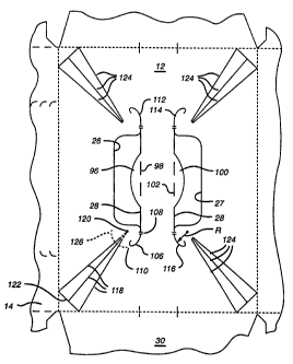
The handle arrangement formed on panel 12 may be seen in greater detail
by reference to Fig. 7. A cushion flap 96 is disposed along the generally
straight
inner edge 28 of aperture 26, connected to panel 12 by fold line 98. A similar
cushion flap 100 is connected to panel 12 by fold line 102. It will be
recognized
t 25 that in the completed carton, the fold lines 98 and 102 will lie
substantially along
the side edges of the underlying central portion 50 of the reinforcing strip.
CA 02293789 2002-11-12
WO 98/56666 Pf:T/US98J11879
_$_
A cut line 106 extends from an end of aperture 26 along the line defined by
the inner edge 28 of the aperture. A nick 108 may join the portions of
paperboard
on each side of the cut line 106 until such time as the nick is broken by use
of the
handle.
Continuing to refer to Fig. 7, the cut line 106 curves away from the
notional strip defined between the apertures 26 and 27, and terminates is a J-
shaped
cut 110.
A similar cut line 112 extends from the opposite end of aperture 26, and
similar cut lines 114 and 116 extend from the ends of aperture 27.
A plurality of stress-diverting score lines 118 are formed into panel 12 to
extend .from adjacent aperture 26 to the respective corner of top wall panel
12 at side
wall panel 14 and end panel 30, in a manner similar to that taught in U.S.
Patent No.
5,307,932. In a preferred embodiment of the present invention, three such
scare
1~~ lines 118 are provided, and extend in diverging fashion from a point 120
located
closely adjacent the edge of aperture 26. (For manufacturing reasons, the
portion of
score lines I 18 immediately at and adjacent to point 120 are not formed. This
has no
effect on handle performance, so long as the termination point of the formed
score
lines is positioned as will be described herein.) A cut line 122 extends
diagonally
2« across the corner of top wall panel 12, at which the group of score lines
118
terminates.
Similar groups of score lines 124 extend from adjacent the ends of tear lines
112, 114 and 116 toward the respective corners of top panel 12.
In the specific embodiment disclosed, three diverging score lines are shown
2.'i in each group. However, other arrangements of score lines may be used
with the
handle disclosed herein. For example, conventional, single score lines
extending
toward each corner may be used. Alternatively, the multiple-score line
CA 02293789 1999-12-08
WO 98/56b66 PCT/US98/11879
-9-
arrangements shown in U.S. Patents Nos. 5,379,944 or 5,385,234 may be used.
Still other arrangements could be used. In any case, the score lines extend
from
adjacent the hand apertures to the respective corners of the top wall panel.
It will be seen from Fig. 7 that the handel aperture 26 (as well as aperture
27) is formed with a width of "W". For cartons for use in packaging beverage
cans, it is expected that the width W will be less than or equal to the can
radius,
although this dimension is determined more by the needed width for insertion
of the
user's hand, balanced by the need to avoid an overly large opening which may
adversely affect package security.
As shown in Fig. 7, and with specific reference to cuts 106 and 116, in the
preferred embodiment, the cut lines 106, 112, 114 and 116 curve away from the
notional strip along a radius of curvature "R" which is substantially one-half
W.
The cut preferably extends through a degree of curvature of approximately 90
° .
Score lines 118 can be seen to terminate inside the radius of curvature of
cut line 106. While it is not necessary for the score lines 118 to extend
completely
to the edge of aperture 26 (and may not be desirable for manufacturing
reasons), it
is important that the score lines effectively pass by the J-shaped cut 110 and
into
the area within the arc defined by the curvature of cut 106. (Note phantom
line
126.)
In use, when lifting the loaded carton, a user inserts the hand and/or forgers
into the apertures 26 and 27 and grasps the portion of panel 12 therebetween.
The
user then lifts the carton. The weight of the carton causes cut lines 106,
112, 114
and 116 to open. This directs the tear stress introduced by lifting the carton
along
the cut lines, away from the high-stress region of the carton, and to the J-
shaped
cuts 110 which resist further tearing. Because of the stress-relieving score
lines
118 and 124 which extend from within the curvature of cut lines 106, 112, 114
and
CA 02293789 2002-11-12
WO 98/56666 PCT/US98/11879
-10-
116, most of the stress is directed along these score lines toward the carton
comers.
It should be readily recognized that while in the preferred
embodiment, the present invention has been described in connection with a
carton
for packaging two tiers of cans, the handle structure may also be used with a
carton
for packaging only a single tier of cans, or for a carton for packaging
bottles, jars
or other containers or articles. The containers rnay be oriented vertically,
as
described herein, or horizontally.
Further, it should be recognized that various handle reinforcing means other
than the folded panel 50 described herein may be used with the disclosed
handle.
For example, rather than a single top panel 12 and the reinforcing structure
comprising portions 42, 44 and 50, a lapped top panel of a type generally
known in
the art may be used. In such an embodiment, the overlap between the two top
panel
portions forms a double-ply strip which extends down the center of the carton
top
wall. An example of a carton of this type may be seen in U.S. Patent No.
5,427,242.
The handle structure is formed into the lapped top panel in the same manner as
the
handle structure described herein, as will be readily appreciated by those
skilled in
the art. In such an embodiment, the tear lines 106, 112, 114 and 116 are
formed to
begin along the edges of the lapped portion, and curve away therefrom.
It will be further recognized that it is not necessary that the handle
apertures
be formed with exactly the shape disclosed herein. As one example, the
apertures
may be formed as ovals having completely rounded ends as shown in the
above-referenced U.S. Patent No. 5,427,242. In such a case, the cut lines and
score lines are provided in the same manner as described herein. Other shapes
for
the handle apertures will be readily apparent to those skilled in the art.
CA 02293789 2002-11-12
-11-
Moreover, the handle arrangement of the present invention may be used with
cartons having a different shape than that described herein. As one example, a
carton having "beveled" corners may be used, similar to that shown in U.S.
Patent
No. 5,480,091. In such a case, the handle is formed into the carton in the
same
manner as described herein, except that the edge of the beveled corner formed
at
each corner of the top wall panel functions as the cut 122 described in
connection
with the preferred embodiment.
It will also be recognized that as used herein, directional references such as
"top", "bottom", "end" and "side" do not limit the respective panels to such
orientation, but merely serve to distinguish these panels one from another.