Note: Descriptions are shown in the official language in which they were submitted.
CA 02294001 1999-12-20
WO 98/59188 - PCT/US98/11411
Fluidic Drive Apparatus
= TECHNICAL FIELD
The present invention pertains to fluid drive systems. More particularly, one
embodiment of the
= present invention concerns a drive system for bicycles.
BACKGROUND ART
Previous transmissions have utilized a wide variety of devices to transfer
rotary power from one
location to another. Conventional automobile transmissions employ a complex
combination of gear and
fluid drive systems. Conventional bicycles usually depend upon rotating
sprockets, chains and derailleurs.
Several examples of attempts to provide improved mechanical transmissions are
described below.
In U.S. Patent No. 3,850,448, issued on 26 November 1974, Stewart describes a
vehicle that can
be bodily powered without the aid of a combustion motor.
In U.S. Patent No. 4,313,714, issued on 2 February 1982, Kubeczka discloses a
high pressure
radial pump for delivering a stream of liquid at high velocity for cleaning of
various surfaces.
In U.S. Patent No. 4,546,990, issued on 15 October 1985, Harriger describes a
hydraulic drive
system having a variable speed drive mechanism.
In U.S. Patent No. 4,684,143, issued on 4 August 1987, Sato discloses a
stepless speed change
device.
In U.S. Patent No. 4,688,815, Smith discloses a manually powered hydraulically
driven bicycle.
In U.S. Patent No. 4,975,025, issued 4 December 1990, Yamamura et al. disclose
a hydraulic
radial piston pump having a set of pistons arranged radially around the rotary
shaft for sequential
reciprocating motion for suction and delivery of working oil.
U.S. Patent No. 5,112,111, issued 12 May 1992 to Addington Resources, Inc.
describes an
apparatus for mining aggregate material from a seam.
In U.S. Patent No. 5,116,070, issued 26 May 1992, Becoat describes a dual
wheel driven bicycle
which uses an elongate flexible shaft or cable to provide rotational movement
to the front wheel.
U.S. Patent No. 5,230,519, issued on 27 July 1993 to Honda Motor Co., Ltd.
discloses a
hydraulically operated power transmission apparatus.
In U.S. Patent No. 5,281,104, issued on 25 January 1994, Bublitz discloses a
sequential
' 20 displacement piston pump.
In U.S. Patent No. 5,342,075, issued on 30 August 1994, Williams discloses a
variable speed
drive for a bicycle.
1
CA 02294001 2006-08-16
79041-13
2
In U.S. Patent No. 5,346,234, issued on 13
September 1994, Kadaja describes a hydraulic drive mechanism
for tricycles and the like that comprises a variable volume,
positive displacement hydraulic pump and a hydraulic motor.
In U.S. Patent No. 5,351,575, issued on 4 October
1994, Overby discloses a pumping propulsion system.
U.S. Patent No. 5,354,082, issued on 11 October
1994 to Topeak, Inc. discloses a mudguard for a bicycle.
U.S. Patent No. 5,358,078, issued on 25 October
1994 to Fichtel & Sachs, AG discloses a hydraulically
operable disk brake for bicycles or similar vehicles.
U.S. Patent No. 5,385,359, issued on 31 January
1991, discloses a stabilization device for front wheel drive
bicycles.
In U.S. Patent No. 5,362,278, issued on 8 November
1994, Bergles et al. discloses a chain driving mechanism for
a bicycle or the like.
U.S. Patent No. 5,378,201, issued on 3 January
1995, discloses a multi-geared bicycle transmission assembly
comprising internal gear sets.
In U.S. Patent No. 5,387,000, issued on 7 February
1995, Sato discloses a hydraulic drive system for bicycles
and the like.
U.S. Patent No. 5,390,565, issued on 21 February
1995 to Maeda Industries, Ltd., discloses a bicycle speed
change system.
U.S. Patent No. 5,390,946, issued on 21 February
1995, discloses a sifting clutch for a dual-wheel driven
bicycle.
CA 02294001 2006-08-16
79041-13
2a
U.S. Patent No. 5,407,395, issued on 18 April
1995, discloses a steplessly variable belt drive for
bicycles.
A brochure from Banjo Corporation in
Crawfordsville, Indiana, advertises a product called "Dry
Mate Polypropylene Dry Disconnect" and provides
specifications for the product.
DISCLOSURE OF THE INVENTION
In one aspect of the present invention, there is
provided an apparatus comprising: a first housing means for
containing a fluid and including an inlet port and an outlet
port; a second housing means for containing said fluid and
including an inlet port and an outlet port; a first conduit
means and a second conduit means for conveying said fluid
between said first housing means and said second housing
means; a first turbine means contained in said first housing
means and including a first shaft means for transferring an
external torque to said first turbine means, said first
turbine means converting said external torque to a pressure
imposed on said fluid; a second turbine means contained in
said second housing means for converting said-pressure
imposed on said fluid to rotational energy, and including a
second shaft means for transferring said rotational energy
to an external torque; and a ratio adjustment means for
changing the ratio of the torques of said first shaft means
and said second shaft means, said ratio adjustment means
being disposed around one of said first shaft means and said
second shaft means and comprising a fixed disc and a
rotatable disc, both said fixed disc and said rotatable disc
having apertures, the discs being mounted side by side such
that said turbines force said fluid through said ratio
adjustment means in a substantially axial direction.
CA 02294001 2006-08-16
79041-13
2b
An embodiment of the present invention comprises a
torque converting linkage which employs two turbines in
fluid filled chambers. An external torque rotates the first
turbine, which forces fluid into a chamber containing a
second turbine. The displaced fluid rotates the second
turbine, furnishing rotational power to a device attached to
a shaft which the second turbine rotates. The housings
enclosing the two turbines are filled with a force
transmitting fluid, and are coupled by two conduits. Each
housing has an inlet and an outlet which provide connections
for the conduits.
In a preferred embodiment of the invention, the
housing includes a volute which directs fluid against the
vanes of the turbines to optimize the transfer of energy.
The invention may also include a ratio
CA 02294001 1999-12-20
WO 98/59188 - PCT/US98/11411
adjustment device, which controls the flow of fluid to the turbines, and a
pressure adjustment device,
which changes the working pressure within the housings. Other features which
may be incorporated into
the invention include a quick connect device, a dual flow conduit, a dual flow
quick connect device, a
reversing valve and automatic shifting and torque adjustment devices.
One embodiment of the invention is intended for use with bicycles. The
invention offers the
advantage of transferring power from one location to another even if the two
shafts are not in line, or if
the two turbines are not mounted in the same plane or their locations are
moving with respect to each other.
The invention may be utilized in a wide variety of mechanical devices,
including automobiles, machinery,
tools and appliances.
An appreciation of other aims and objectives of the present invention and a
more complete and
comprehensive understanding of this invention may be achieved by referring to
the description of preferred
and alternative embodiments that follows and by referring to the accompanying
drawings.
A BRIEF DESCRIPTION OF THE DRAWINGS
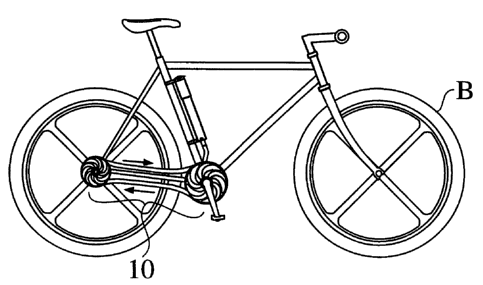
Figures 1, 2 and 3 present views of the present invention mounted on a
bicycle. Figure 1 shows
an embodiment which provides rear wheel drive. Figure 2 shows an embodiment
which provides front
wheel drive. Figure 3 shows an embodiment which provides both front and rear
wheel drive.
Figures 4, 5 and 6 offer views of one embodiment of the present invention,
showing a driver
turbine and a reactor turbine each mounted in housings coupled by fluid-filled
conduits.
Figures 7, 8, 9 and 10 supply exploded views of one embodiment of the
invention, revealing a
turbine, a shaft, a volute, a housing and fluid ports.
Figures 11, 12, 13, 14 and 15 furnish views of a ratio adjustment device,
which functions as an
adjustable aperture that controls fluid flow to the turbines.
Figures 16 and 17 contain additional views of the ratio adjustment device.
Figures 18, 19, 20, 21, 22, 23, 24 and 25 depict various examples of the ratio
adjustment device.
Figures 26, 27 and 28 exhibit three views of a pressure adjustment device that
may be employed
to change the working pressure experienced by the turbines.
Figures 29, 30 and 31 portray a quick connect assembly that is used to connect
or disconnect the
fluid conduits from the turbine housings.
Figure 32 supples views of some of the various impeller configurations which
may be used to
= 30 implement the invention.
Figures 33 and 34 provide illustrations of an auto-dial assembly, which is
used to adjust the ratio
adjustment device to maintain constant torque pressure on the driver turbine
to facilitate automatic shifting
or ratio adjustment.
3
CA 02294001 1999-12-20
WO 98/59188 PCT/US98/11411
BEST MODE FOR CARRYING OUT THE INVENTION
1. Preferred Embodiments of the Invention
Figures 1, 2 and 3 show different embodiments of the present invention 10
mounted on a
conventional bicycle B. Figures 4, 5 and 6 reveal the details of a generalized
embodiment of the present
invention 11. The embodiment portrayed in Figures 4, 5 and 6 comprises two
disc-shaped turbines 12 and
14 which rotate on shafts 16 and 18, and which are enclosed by housings 20 and
22. Each housing has
a pair of fluid ports, an inlet and outlet. The inlet and outlet ports on the
impeller turbine housing 20 are
marked 24 and 34. The inlet and outlet ports on the reactor turbine housing 22
are marked 26 and 28. The
two housings 20 and 22 are coupled by a pair of conduits 32 and 34, forming a
closed loop. Conduit 32,
the driver conduit, connects the outlet port 24 on the impeller housing 20 to
the inlet port 26 on the reactor
housing 22. Conduit 34, the return conduit, connects the outlet port 28 on the
reactor housing 22 to the
inlet port 30 on the impeller housing 20. The housings 20 and 22, as well as
the conduits 32 and 34, are
all filled with a generally incompressible fluid 36. The first turbine
functions as an impeller 12, which is
rotated by an external force which is applied to the impeller turbine shaft
16. The second turbine functions
as a reactor 14, which is turned by the motion of the fluid 36 that is forced
by direct pressure away from
the impeller turbine 12 and through driver conduit 32. The fluid 36 then acts
on the passive reactor turbine
14, inducing the reactor turbine 14 to rotate its shaft 18. The spent fluid 36
then returns to the housing
containing the impeller turbine 12 through return conduit 34. In one
embodiment of the invention, the
fluid 36 is a natural or synthetic gel or lubricant that is capable of
withstanding high temperatures and that
has a very low freezing temperature.
Each turbine 12, 14 includes generally spiral-shaped vanes 38 which radiate
from their centers.
The vanes 38 each have a convex and a concave side. In Figure 4, the impeller
turbine 12 is shown
rotating in the clockwise direction as a result of the external torque imposed
on shaft 16. In the specific
case of a bicycle, a crank with pedals would be fixed to shaft 16. When the
external torque rotates the
impeller turbine, the fluid 36 is "caught" against the concave side of each
vane 38 and pushed out of the
impeller housing 20 into its outlet port 24, which is connected to driver
conduit 32. The fluid 36 then
enters the reactor housing 22 through its inlet port 26, and is then caught by
the vanes 28 on the concave
side of the reactor turbine 14. The displaced fluid forces the reactor turbine
14 to rotate its shaft 18, and
then exits the reactor housing 22 by passing through reactor housing outlet
port 28 into the return conduit
34. The fluid 36 completes its joumey by arriving back in the impeller housing
20 through its inlet port
30.
The embodiments shown in Figures 4, 5 and 6 are generalized versions of the
invention, and are
provided only to disclose the invention in one of its more simple fomis. The
turbines 12 and 14 represent
only one of the many embodiments of the invention. Similarly, the spiral vanes
38 constitute only one of
the many variations which may be employed to implement the invention. Any
means which transmits a
-4
CA 02294001 1999-12-20
WO 98/59188 PCT/US98/11411
medium under pressure from a first rotating turbine to a second rotating
turbine may be utilized to practice
the invention.
Figure 5 discloses an important benefit offered by the invention. Because the
conduits 32 and
34 may be flexible, the turbines 12 and 14 may be located in different planes
as shown in Figure 5. Unlike
a conventional chain drive on a bicycle, where the rotating sprockets must be
located in-line and generally
in the same plane in a fixed location, the present invention offers a means
for transmitting power without
the geometric constraints of previous mechanical drive systems. The rotating
shafts and associated housing
and turbines may be moved to other non coplanar locations with respect to each
other while in operation.
Figure 6 illustrates an altemative embodiment of the invention, showing the
housings 20 and 22
connected in a configuration which is different from that shown in Figure 4.
In Figure 4, the impeller and
the reactor turbines rotate in opposite directions. By changing the position
of the turbine housings as
shown in Figure 6, both turbines may be made to rotate in the same direction.
Figure 7 furnishes an exploded view of an embodiment of the present invention
which includes
a turbine 14, a shaft 18, a housing 20, inlet and outlet ports 24 and 30, and
a volute 40. In this embodiment
of the invention, the volute 40 comprises two pieces and encloses the turbine
(14) within the turbine
housing (20). The volute may be a generally disc-shaped element which is
shaped to direct the flow of the
fluid 26 within the housing to optimize the transfer of power to and from the
turbines. The volute 40 may
comprise two separate pieces which are installed on either side of a turbine,
or may be integrally formed
as part of a housing. The volute 40 may be an integral part of one of said
housing means 20, 22 or may
be in the form of a replaceable cartridge. The volute 40 may have a number of
openings 41 formed in its
sides, or may incorporate venturi or contours which are designed to direct the
fluid flow within a turbine
housing.
Figure 8 presents a side view of the housing 20, showing an inlet and an
outlet port 24 and 30.
Figure 9 offers another exploded rendering, depicting the turbine 14, shaft
18, housing 20 and volute 40
in a perspective view. Figure 10 furnishes yet another illustration of this
same embodiment of the present
invention.
Figures 11, 12, 13, 14 and 15 contain sequential views of a ratio adjustment
device 42, which
functions as an adjustable aperture or iris that controls fluid flow to or
from the turbines. In one
embodiment of the invention, the ratio adjustment device 42 changes the torque
ratio and/or speed of one
of the shafts with respect to another of the turbine shafts. The ratio
adjustment device 42 may comprise
two discs mounted side by side. Both the first fixed disc 44 and the second
movable disc 46 are formed
with spiral-shaped openings 48. The second movable disc 46 is rotated so that
the overlap of the spiral
openings on each disc create a variable aperture for the flow of the force
transmitting fluid 36. The volume
and position of fluid that flows to a turbine is determined by the size and
shape of the opening that is
created by the superposition of the two discs 44 and 46.
5
CA 02294001 1999-12-20
WO 98/59188 PCT/US98/11411
Figures 16 and 17 contain additional views of the ratio adjustment device. The
ratio adjustment
device 42 may be integrated with a volute 40 or with a housing 20, or may be
manufactured as a separate
unit. The ratio adjustment device 42 may be controlled by a variety of
different mechanisms, including
a lever, a cable, a belt, gears, rollers or springs or magnetic actuator, as
shown in Figures 18 through 25.
Figures 26, 27 and 28 illustrate a pressure adjustment device 50 that is used
to control the fluid
pressure inside the turbine housings 20 and 22. In one embodiment of the
invention, the pressure
adjustment device 50 comprises a pump which increases or reduces the pressure
in the space inside one
or both of the housings 20, 22. Figure 27 depicts a pressure adjustment device
50 comprising a housing
52, a pressure gauge 54, a release vaive 56, a bladder membrane 58, a pumping
mechanism 53 and a vent
60. Figure 28 shows a pressure adjustment device 50 mounted on a bicycle
frame. The pressure
adjustment device may also be employed to capture any gas that may accumulate
in the force transmitting
fluid 36.
Figures 29, 30 and 31 reveal the details of a quick connect assembly 62 that
may be used to
connect or disconnect the fluid conduits 32 and 34 from the turbine housings
20 and 22. In one
embodiment of the invention, the quick connect assembly 62 includes two
pivoting ball valves 64 located
in a housing 66. One of the balls has a mating surface dimple 68, while the
other has a mating surface ring
70. The use of the quick connect assembiy 62 allows for quick and easy
decoupling without re-
pressurizing or bleeding the system. This feature is especially useful when
the invention is incorporated
with a bicycle, where it is important to be abie to remove and to reattach the
front or rear wheel frequently.
Il. Alternative Embodiments of the Invention
Figure 32 supplies views of some of the various impeller configurations 72
which may be used
to implement the invention. These depictions are provided to educate the
reader about the wide variety
of embodiments which may be employed to practice the invention, and are not
intended to limit the scope
of the Claims which follow.
Figures 33 and 34 provide illustrations of an auto-dial assembly 74, which is
used to adjust the
ratio adjustment device to maintain constant torque pressure on the driver
turbine. The auto-dial assembly
74 utilizes the pressure differential between the two ports of a housing to
automatically control the ratio
adjustment device 42. An auto-dial pressure adjuster 76 is moved by increasing
the pressure of the fluid
flowing through an internal port. This action, in tum, rotates the movable
disc 46 of the ratio adjustment
device 42.
The invention may also include a torque adjustment device 78 which uses the
pressure differential
of the fluid at the two ports on a housing to automatically adjust the ratio
adjustment device 42. When
fluid pressure at an internal inlet falls, fluid is forced from the outlet
side into an internal fluid expansion
chamber 80 forcing a torque adjuster 82 and the fluid within the expansion
chamber 80 to alter the position
of the rotatable disc 46 of the ratio adjustment device 42.
6
CA 02294001 1999-12-20
WO 98/59188 PCT/US98/11411
The invention may also include a dual flow conduit incorporating the driver
conduit 32 and the
return conduit 34 into a single element.
. The invention may also include dual flow impeller housing inlet/outlet parts
incorporating
impeller housing inlet port 30 and impeller housing outlet port 24 into one
element.
The invention may also include dual flow reactor housing inlet/outlet parts
incorporating reactor
housing inlet port and reactor housing outlet port 28 into one element.
The invention may also include a dual flow quick disconnect assembly to allow
quick and easy
disconnection and re-connection of dual flow conduit to dual flow impeller
housing inlet/outlet port or dual
flow reactor inlet/outlet port.
The invention may also include a reversing valve 84 which redirects the
direction of fluid flow
through the housings 20 and 22.
INDUSTRIAL APPLICABILITY
One embodiment of the present invention is intended for use with bicycles. The
invention may
also be employed in a wide variety of mechanical devices, including
automobiles, machinery, tools and
appliances.
CONCLUSION
Although the present invention has been described in detail with reference to
a particular
preferred embodiment, persons possessing ordinary skill in the art to which
this invention pertains will
appreciate that various modifications and enhancements may be made without
departing from the spirit
and scope of the Claims that follow. The List of Reference Characters which
follows is intended to
provide the reader with a convenient means of identifying elements of the
invention in the Specification
and Drawings. This list is not intended to delineate or narrow the scope of
the Claims.
LIST OF REFERENCE CHARACTERS
10 Fluidic Drive Apparatus
11 Generalized embodiment of the invention
12 Impeller turbine
14 Reactor turbine
16 Impeller turbine shaft
18 Reactor turbine shaft
20 Impeller turbine housing
7
CA 02294001 1999-12-20
WO 98/59188 PCT/US98/11411
22 Reactor turbine housing
24 Impeller housing outlet port
26 Reactor housing inlet port
28 Reactor housing outlet port
30 Impeller housing inlet port
32 Driver conduit
34 Return conduit
36 Fluid
38 Vanes
40 Volute
41 Volute opening
42 Ratio adjustment device
44 Fixed disc
46 Rotating disc
48 Aperture
50 Pressure adjustment device
52 Housing
53 Pumping mechanism
54 Gauge
56 Release valve
58 Bladder membrane
60 Vent
62 Quick disconnect assembly
64 Ba11 valves
66 Housing
68 Mating surface dimple
70 Mating surface ring
72 Examples of impeller configurations
74 Auto-dial device
76 Pressure adjuster
78 Torque adjustment device
80 Expansion chamber
82 Torque adjuster
84 Reversing valve
B Bicycle
8