Note: Descriptions are shown in the official language in which they were submitted.
CA 02294020 1999-12-10
WO 98/59249 PCT/US98/13338
DUAL INJECTOR FOR CHEMILUMINESCENCE
IMMUNOANALYZING SYSTEM
Field of the Invention
The present invention relates to the field of immunoassay procedures, and
more particularly to a dual injector design for use with compounds which
enable
detection of immunological substances or other analytes through
chemiluminescence.
Background of the Invention
Immunoassay is an analytical technique widely used in medicine and in the
biological sciences. The term "immunoassay" as used herein encompasses
analytical methods for detecting, locating or quantifying biological
substances by
use of a label. Generally, a "label" is attached to a molecule of the
substance of
interest. The presence of the labeled molecule can then be detected by
suitable
means.
There are various types of immunoassay in common usage. In one type of
immunoassay, a sample containing both an unknown and a labeled antigen of
interest is incubated with an antibody specific for that antigen. If the
unknown
also contains the antigen, then both the labeled and unlabeled antigens
compete for
binding sites on the antibody. The antibody can be immobilized on a solid
support, such as a test tube, glass beads, latex particles, or the like.
Incubation is
followed by a separation step in which the antigen bound to the antibody on
the
support is separated from unbound antigen. Through measurement of the amount
of bound labeled antigen, the presence and/or quantity of similar, unlabeled
antigen can be determined. Thus, the detected level of the labeled antigen
(e.g.
counts per minute of radioactivity) is an inverse function of the
concentration of
the unlabeled antigen.
A second type of immunoassay is known as sandwich immunoassay. In
this method, an antibody rather than an antigen is labeled. A sample
containing an
unknown is incubated with an immobilized antibody. Antigens, if present in the
CA 02294020 1999-12-10
WO 98/59249 PCT/US98/13338
sample, will bind to the antibody. After incubation, unbound material is
removed
by a separation step. In a second incubation with a solution of labeled
antibody,
the bound antigen is "sandwiched" between the immobilized antibody and the
labeled antibody which adheres to the antigen. After a second separation, the
amount of labeled antibody is determined. Detection of labeled antibody is
indicative of the presence of antigen.
In general, a commonly used type of label is a radioactive substance, which
can easily and accurately be detected. However materials labeled radioactively
often have a short shelf life, both because of radioactive decay of the label
and
because radiation degrades the labeled molecule. Further, handling of
radioactive
substances entails risks to laboratory personnel.
In contrast to radioimmunoassay, luminometric immunoassay utilizes a
chemiluminescent compound as the label. Such a compound is capable of
undergoing a reaction (usually oxidative) in which light is a product. The
light
emission is measured by appropriate devices, and in certain cases, the light
intensity is indicative of the quantity of labeled material. Known
chemiluminescent substances suitable for use as inununoassays include luminol,
isoluminol, and the various acridinium esters, for example, as noted in the
prior art
literature, and discussed in U.S. Patent No. 5,395,938, to Ramakrishnan, which
is
commonly assigned with the present application.
Luminometric immunoassay procedures overcome many of the problems
encountered with radioimmunoassay, namely risk to personnel and the short
shelf
life due to radioactive decay. Additionally, for example, luminometric
immunoassay is easier to use, requires a shorter incubation time, solves
problems
related to safety, waste disposal, and regulatory compliance, has greater
sensitivity,
utilizes more stable reagents, and improves ease of manufacture and storage.
It is known in the prior art to employ an automated chemiluminescence
immunoassay analyzer for assaying specimens. Such automated systems typically
employ a set of two trigger reagents A and B which can trigger a
chemiluminescent reaction, in labels such as either luminol or acridinium. The
2
CA 02294020 1999-12-10
WO 98/59249 PCT/US98/13338
trigger reagents are sequentially injected into a receptacle, such as the well
of a
cuvette, when the cuvette is disposed in the measuring chamber of the
analyzer.
When the chemiluminescent reaction is initiated by the injection of the
trigger
reagents, the flash resulting from the oxidation of the label to its excited
state, and
its subsequent return to the ground state, which typically lasts about two
seconds,
is detected by the system integrated luminometer. This value is expressed in
relative light units (RLU), and compared to a calibrated test standard in
order to
determine the amount of bound labeled antibody or antigen in the patient's
blood.
Assays are available to test a variety of body functions, including, for
example, the adrenal/pituitary system, anemia, bone and mineral metabolism,
growth, thyroid, tumor markers, hypertension, neonatal conditions, and the
reproductive system. It would be advantageous to be able to perform a
plurality of
such assays, of different types, on a single immunoassay instrument, in a
single
procedure, using a plurality of labels, and a plurality of triggering reagent
sets to
initiate a chemiluminescent reaction for each of the labels sequentially. It
would
further be advantageous to be able to inject the triggering reagents of each
set in
such a manner that the walls of the cuvette well are washed down and cross-
contamination between trigger reagents exiting each of the exit ports of the
trigger
reagent injector is substantially eliminated.
Summary of the Invention
A dual injector for an automated immunoassay instrument is provided
which allows the sequential detection of two different chemiluminescence
labels
within one instrument. The injector has four carefully designed orifices. The
orifices are designed to work in two pairs. Orifices one and two can be used
to
inject trigger reagents A and B which can trigger a chemiluminescent reaction,
such as acridinium. Orifices three and four can inject trigger reagents C and
D for
triggering a chemiluminescent reaction, such as luminol. The two pairs can be
used in a sequential manner to generate signals in the wells of a cuvette.
Thus, it is
possible to run a plurality of assays, such as both acridinium and luminol
based
3
CA 02294020 1999-12-10
WO 98/59249 PCTIUS98/13338
assays, for example, on one instrument.
The injector is designed to fit into the wells of the cuvette and to inject
the
triggers in a manner which efficiently resuspends magnetic particles of one to
eight
microns in diameter. The design also prevents the contamination or carryover
of
trigger solutions from one orifice to another.
More particularly, in one aspect of the invention, a dual injector system for
an automated chemiluminescent immunoassay instrument is provided which
comprises a first pair of injector orifices for injecting first and second
trigger
reagents into a well containing a chemiluminescent label and a second pair of
injector orifices for injecting third and fourth trigger reagents into a well
containing a chemiluminescent label. This advantageous arrangement permits the
running of a plurality of assays in a single instrument.
In another aspect of the invention, an injector system for an automated
chemiluminescent immunoassay instrument is provided which comprises an
injector body having a longitudinal axis, a first injector orifice disposed in
the
injector body for injecting a first trigger reagent into a well containing a
chemiluminescent label; and a second injector orifice disposed in the injector
body
for injecting a second trigger reagent into a well containing a
chemiluminescent
label. Advantageously, the first injector orifice is disposed at a compound
angle
with respect to the longitudinal axis, such that the first orifice is disposed
at an
angle to the axis in a plurality of planes, preferably two. This allows the
orifice to
inject the first trigger reagent at an angle into the curette well, so that it
washes the
magnetic particles into the assay solution. It also allows the employment of
four
injector orifices for injecting more than one set of trigger reagents in a
single
immunoassay instrument, without contaminating cross-talk between sets of
orifices.
The invention, together with additional features and advantages thereof,
may best be understood by reference to the following description taken in
conjunction with the accompanying illustrative drawing.
4
CA 02294020 1999-12-10
WO 98/59249 PCT/US98/13338
Brief Description of the Drawing
Fig. 1 is a schematic view illustrating an automated chemiluminescence
immunoanalyzing system of the type usable with the present invention;
Fig. 2 is a top plan view, in isolation, of the trigger injection apparatus
constructed in accordance with the principles of the present invention;
Fig. 3 is a perspective view of the trigger injection apparatus illustrated in
Fig. 2;
Fig. 4 is a perspective view, in an exploded format, of a beam for
supporting a trigger injector constructed in accordance with the principles of
the
present invention;
Fig. 5 is a bottom plan view of a cuvette strip for use in receiving the
triggers injected by the trigger injector of the present invention;
Fig. 6 is a side plan view of the cuvette strip illustrated in Fig. 5;
Fig. 7 is a top plan view of the cuvette strip illustrated in Fig. 5;
Fig. 8 is a perspective view, in isolation, illustrating the top side and
distal
end of a trigger injector constructed in accordance with the principles of the
present invention;
Fig. 9 is a perspective view, in isolation, illustrating the top side and
proximal end of the trigger injector shown in Fig. 8;
Fig. 10 is a perspective view, in isolation, illustrating the bottom side and
proximal end of the trigger injector shown in Fig. 8;
5
CA 02294020 1999-12-10
WO 98/59249 PCT/US98/13338
Fig. 11 is a plan view of the top side of the trigger injector shown in Fig.
8,
illustrating in phantom each of the four trigger injection passages;
Fig. 12 is a plan view of the right side of the trigger injector shown in
Fig. 8;
Fig. 13 is a plan view of the left side of the trigger injector shown in Fig.
8;
Fig. 14 is a cross-sectional view of the trigger injector shown in Fig. 8,
taken along lines 14-14 of Fig. 12;
Fig. 15 is a cross-sectional view of the trigger injector shown in Fig. 8,
taken along lines 15-15 of Fig. 12;
Fig. 16 is a plan view of the distal end of the trigger injector shown in
Fig. 8;
Fig. 17 is a cross-sectional view of the trigger injector shown in Fig. 8,
taken along lines 17-17 of Fig. 16; and
Fig. 18 is a plan view of the proximal end of the trigger injector shown in
Fig. 8.
Description of the Invention
Referring now to Figure 1, a schematic view of an automated
chemiluminescence immunoanalyzer or luminometer 10 of the type utilized in the
subject invention is illustrated. The luminometer 10 includes a housing 12
having
a measuring chamber 14 therein, in which is disposed a sample cell 16, on
which a
tag or label has been incubated. In a preferred embodiment, the label may be
an
acridinium label, which may be intended, for example, for the quantitative
6
CA 02294020 2003-07-22
determination of TSH concentrations in human serum, or alternatively, for the
quantitative determination ot' Human Growth Hormone in human serum. In order
to initiate the chemiluminescence reaction, a Trigger I reagent 18, which
preferably comprises hydrogen peroxide in diluted acid, and a Trigger 2
reagent
20, which preferably comprises a strong base, such as diluted sodium
hydroxide.
are injected into the measuring chamber 14 by means of an in{ection apparatus
22,
for oxidizing the acridinium ester. The oxidized product is in an excited
state.
The subsequent return to ground state results in the emission of light which
is
quantified in 2 seconds by a photomultiplier tube 24 and a photon counter 26.
in
known fashion, and is expressed in relative Iiglit units (RLU) by the system
integrated luminometer 10.
With reference now to Figures 2, 3, and 8-18, the injection apparatus 22 of
Figure 1, modified in accordance with the principles of the invention to
accommodate the injection of two different trigger reagent sets, will be
described.
1'.> The injection apparatus 22 includes an injector 28, which is preferably
fabricated
of an inert machined plastic, such as PEEK (polyetheretherketone), or,
alternatively, of' an inert material such as PTFE (TEFLON*), which may be
partially
molded and thus less expensive to manufacture. Of course, other biocompatible
materials and methods of manufacture may be used, if desired. Inlet fittings
30,
32, 34, and 36 are each adapted to receive a trigger reagent from a valve or
pump
connected to respective reagent reservoirs (not shown) for delivery to the
injector
28 through fluid lines 38, 40, 42, and 44, respectively. Between the fittings
30, 32,
34, and 36, and the injector 28, is disposed a bulkhead plate 46, which is
adapted
for installing the tubing 38, 40, 42, and 44 to a bulkhead in the luminometer
10 in
combination with fittings 48, 50, 52, and 54. ln turn, the fluid lines 38, 40,
42, and
44 are connected to the injector 28 via threaded fittings 56, 58, 60, and 62,
respectively. The fittings 56, 58, 60, and 62 include o-rings, and are
arranged to
adjust and secure the tubes to the injector 28 by manipulating the threaded
engagement between the fittings 56, 58, 60, and 62 and injector orifices 64,
66. 68,
and 70 disposed on the proximal end 72 of the injector 28 (Figs 3, 9, and 10).
* trade-mark 7
CA 02294020 1999- 12- 10 ;~;y~.,= y~,,~ r~.y y~
~..
These fittings function to prevent the tubing from moving relative to the
injector
28 when the injector 28 moves up and down in the measuring chamber, as will be
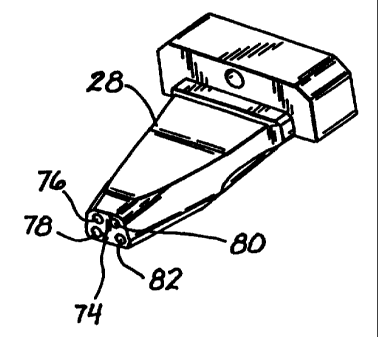
described hereinbelow. On the distal end 74 of the injector 28 are disposed
four
outlet orifices 76, 78, 80, and 82 (Fig. 8).
As is clear from Figs. 11, 14, and 15, proximal orifice 64 of the injector 28
fluidly communicates with distal orifice 78 of the injector via passage 84,
which is
preferably machined (or molded) into the injector body 28. Similarly, orifices
70
and 82 communicate with one another through passage 86, orifice 66
communicates with orifice 76 through passage 88, and orifice 68 communicates
~ 10 with orifice 80 via passage 90.
An advantageous feature of the present invention is that each of the outer
orifices 64, 70, and their associated passages 84, 86, respectively, are
disposed at a
compound angle, meaning that they are disposed at an angle with respect to an
axis
92 (Figs. 11 and 13), which is the longitudinal axis of the injector 28, in
two
dimensions. More specifically, as can be seen from the aforementioned Fig. 11,
the passages 84 and 86 are disposed at an angle s with respect to the axis 92,
or an
angle 2s with respect to one another. Similarly, from Figs. 12 and 13, it can
be
seen that the passages 84 and 86 are each disposed at an angle t from the axis
92 in
a direction transverse to that of angle s. In other words, if the axis 92 were
considered to be the x axis in a coordinate system, the angle s would be
considered
to lie in the y-plane, and the angle t would be considered to lie in the z-
plane. The
presently preferred value for angle s is within the range of 0-45 degrees,
preferably
10-20 degrees, and more preferably about 11 degrees, and the presently
preferred
value for angle t is also within the range of 0-45 degrees, preferably 10-20
degrees,
and more preferably about 16-17 degrees.
The passages 88 and 90, on the other hand are preferably oriented
substantially vertically, so that they are at an approximately 0 degree angle
with
respect to the axis 92 in the z-plane (Figs. 12 and 13) and at an angle u with
respect
to the axis 92 in the y-plane, where the angle u is preferably within the
range of 0-
10 degrees, and more preferably about 3.6 degrees. As will be described more
particularly hereinbelow, the passages 88 and 90 are adapted for injecting the
8
v i5
CA 02294020 1999-12-10
WO 98/59249 PCT/US98/13338
second trigger reagent, for de-exciting the labels in order to produce
detectable
light, and it is therefore important that this trigger be injected straight
into the
cuvette with minimal splashback.
Referring again particularly to Fig. 2, there is also provided a waste line
94,
which communicates with an aspiration pump in the direction of arrow 96, and a
sensing line 98, which has an aspiration needle 100 and an electrical
connection
for determining whether fluid is present in the cuvette after aspiration, in
order to
detect whether there is a clog in the line.
In operation, when an assay is to be performed, the instrument 10 is
operated using software which permits substantially automatic function of the
entire procedure. Initially, a System Wash reagent is used to wash the
instrument's
pipette probes. Afterwards, one or more assays are prepared, and labeled with
a
chemiluminescent tag, such as acridinium, or luminol, or both. For example, a
single patient's fluid specimen could be labeled with an acridinium ester for
detection of an endocrinological condition, and simultaneously labeled with a
luminol tag for detection of tumors. Alternatively, the system could be set up
to
analyze only a single assay, or to analyze two different assays in successive
test
specimens.
By way of example only, a TSH Third Generation assay could be analyzed.
A TSH Third Generation assay is a two site chemiluminescence immunoassay for
the measurement of TSH in human serum. It utilizes one mouse monoclonal
antibody and a goat polyclonal antibody to TSH. The mouse monoclonal antibody
is coupled to biotin, while the goat polyclonal antibody is labeled with an
acridinium ester for detection. TSH is "sandwiched" between these antibodies.
The sample containing TSH is incubated simultaneously with both antibodies.
The formation of a soluble sandwich complex occurs only in the presence of TSH
molecules, which bridge the two antibodies. Therefore, only peptides that
bridge
these two antibodies can be quantitated.
After an initial incubation period, streptavidin coated magnetic particles are
added to the reaction mixture and a second incubation will follow. This allows
for
9
CA 02294020 1999-12-10
WO 98/59249 PCT/US98/13338
a highly specific and efficient means of binding the sandwich complex to the
solid
phase via the high affinity interaction between biotin and avidin. Free
labeled
antibody is separated from the labeled antibody bound to the magnetic
particles by
aspiration of the reaction mixture and subsequent washing using a concentrated
assay wash reagent, as is known in the prior art. The sample reacted solutions
are
contained in wells 110 of a cuvette strip 112, illustrated in Figs. 5-7, which
is
conveyed on a track through the instrument 10, first into the assay wash
station
(not shown) and then into the measurement chamber 14 (Fig. 1). The assay wash
process functions to wash away the unreacted materials in order to reduce
background levels for more precise results. Once the wells 110 of the cuvette
112
containing the washed magnetic particles are transported into the measurement
chamber 14, the injector 28, which is disposed in the mounting aperture 115 of
a
beam 117, is controlled using a stepper motor (not shown), so that the
injector 28
descends vertically on the beam 117 to the top opening of one of the wells 110
of
the cuvette 112, containing the assay. Once the injector 28 is in position,
the
Trigger 1 reagent 18, preferably comprising Nitric acid, is injected into the
cuvette
well 110 from the orifice 78. Advantageously, because the orifice 78 is
disposed
at a compound angle with respect to the axis 92, the Trigger I reagent strikes
the
walls of the well 110 at an angle and then flows downwardly into the sample
fluid
along the walls, thereby washing down the walls and resuspending the
paramagnetic particles in the reacted complex solution.
Once the Trigger 1 reagent has been injected to resuspend the mixture, the
Trigger 2 reagent 20, which preferably comprises sodium hydroxide, is injected
from orifice 76 into the solution. As discussed supra, the orifice 76 is
preferably
disposed at a minimal angle with respect to the axis 92, because it is
desirable to
inject the Trigger 2 reagent straight into the solution with minimal
splashback.
While the Trigger I reagent functions to re-mix the solution and to excite the
chemiluminescent label, the Trigger 2 reagent functions to de-excite the
label,
thereby initiating the chemiluminescent flash for detection and quantification
by
the luminometer. The amount of bound labeled antibody is directly proportional
to
CA 02294020 1999-12-10
WO 98/59249 PCT/US98/13338
the concentration of TSH in the sample solution. Once quantified, the
automated
immunoanalyzer calculates test results for controls and patient samples from
the
observed signal from the calibration curve, and generates a printed report
which
includes patient information.
In the event that a second assay is to be analyzed, involving the use of
different Trigger reagents; such as a Trigger 3 reagent and a T'rigger 4
reagent, for
a luminol label, for example, these reagents may be injected by a separate
pump
through the orifices 80 and 82, respectively, without the need to first stop
the
machine and clean the injection apparatus 22 (Fig. 1). This procedure is
identical
to the one discussed supra with respect to the Trigger I and Trigger 2
reagents. and
it should be noted that the entire procedure could be reversed (i.e. the
luminol test
could be performed first, followed by the acridinium test. Advantageously,
because of the particular relative orientations of the four exit orifices 76,
78, 80,
and 82, and the fact that the orifices 78 and 82 are oriented at a substantial
compound angle with respect to the axis 92, the four orifices are adequately
spaced
on the distal end 74 of the injector 28 such that there is substantially no
"cross-
talk" between the four orifices. In other words, there is substantially no
cross-
contact between reagents exiting from each of the four orifices, and thus no
contamination which might invalidate the assays.
While this invention has been described with respect to various specific
examples and embodiments, it is to be understood that the invention is not
limited
thereto and that it can be variously practiced within the scope of the
following
claims.
11