Note: Descriptions are shown in the official language in which they were submitted.
CA 02294073 1999-12-21
WO 98/39983 PCT/US98/04787
SEQUENTIAL FLASHING FOOTWEAR
BACKGROUND OF THE INVENTION
The present invention relates to lighted footwear and, more
particularly, to footwear with light modules that apply power from a power
source in such a way as to turn on the lights so the safety of the wearer is
improved, the useful life of the power source is extended and an attractive
lighting pattern is created.
At various times in the past, lighted footwear has enjoyed some
popularity. This lighted footwear all has the same basic components, i.e., at
least one light source, a source of power for the light or lights and a switch
of
some sort to apply the output of the power source to the light to cause it to
come on and provide illumination. The lights can be of a variety of types,
e.g.,
incandescent bulbs, electroluminescent panels, and light emitting diodes
(LEDs).
These are popular lights for this purpose because they can be lighted by the
power from small batteries, so that the elements lighting the light can be
encapsulated in the footwear and need not be connected to any external power
source. However, there is no reason that light sources which require a.c.
voltage or current, such as fluorescent lights, could not be used in lighted
footwear, assuming a suitable power source were provided. Consequently, as
used in this application, "light source" is intended to encompass any device
capable of generating detectible light, visible or otherwise, e.g., infrared.
In its simplest form lighted footwear typically has lights in the heel
and along the sole of the footwear, which could be athletic, casual shoes,
formal
CA 02294073 1999-12-21
WO 98/39983 PCT/US98/04787
2
shoes or sandals for men, women or children. A battery, e.g, of three (3)
volts
output, is incorporated in the heel or sole of the shoe and is connected by
wires
to the lights. A switch is provided in the connection wires to control the
illumination of the lights, which switch may be a simple manual switch as
disclosed in U.S. Patent No. 4,158,922 of Dana, III. Thus, whenever the user
wishes the lights to be on, for example, just before he or she goes jogging at
night, he or she can turn on the lights by operating the switch. However, with
such an arrangement the lights would be on continuously until the switch is
turned off.
If the lights are flashed intermittently, there are two advantages.
First, the life of the battery is increased in proportion to the time the
lights are
off during the intermittent flashing. Second, a more attractive eye-catching
display is provided. When running at night, the flashing of the lights makes
the
user more visible, e.g., to motorist, so that the safety of the user is
increased.
One way to achieve a flashing effect is to utilize a motion-activated switch
to
apply power to the lights. This could be a mercury switch which is in the form
of a tube containing a quantity of mercury and having spaced-apart electrical
contacts. The tube is oriented on the footwear so that when the footwear is
flat, there is no connection between the contacts. However, as the footwear
is tilted, as during the taking of a step, the mercury runs down the tube and
closes the contacts. This contact is broken again when the footwear is flat
again at the completion of the step. Thus, as the user walks, the lights come
on and go off. Mercury switch operated lighted footwear is disclosed in U.S.
Patent No. 4,848,009 of Rodgers and the Dana III '922 patent mentioned
above.
In another form of motion-activated switch, the mercury in a
mercury switch is replaced for environmental reasons with a metal ball that
rolls
in the tube. Further, mechanical motion activation can be achieved by the
mechanical lever system disclosed in U.S. Patent No. 2,572,760 of Rikelman.
In addition, intermittent operation of the lights can be achieved by a
pressure
switch. During jogging, whenever the wearer's foot hits the ground the
pressure activates a switch in the shoe which closes the circuit and causes
the
CA 02294073 1999-12-21
WO 98/39983 PCTIUS98/04787
3
Jights to flash. Such a pressure switch is disclosed in European Patent
Application No. 0 121 026 of Dana III.
Another way to achieve an intermittent lighting effect is to
incorporate an electronic circuit into the flashing footwear. This circuit
could be
an integrated circuit= low frequency oscillator or flasher operated by the
switch
and providing the power to the lights. Whenever the switch is closed the
oscillator provides power to the lights at a slow rate, e.g., from 0.5 to
2.5Hz.
Such a flasher could be like the National Semiconductor LM3909 LED
Flasher/Oscillator. Use of this device to provide intermittent lighting is
disclosed
in the Dana III European patent application. The U.S. Patent No. 4,158,922 of
Dana III also discloses a low frequency oscillator made from individual
components which is used in this fashion.
One problem with these prior motion-activated switches, e.g., the
mercury, ball, lever and pressure switches, is that they can remain
continuously
closed, thus allowing the lights to stay on and running the battery down. For
example, if shoes with the mercury, ball or lever switches are placed at an
attitude corresponding to a step in walking, the switch will close and the
lights
will light continuously. Similarly, the shoes with the pressure switch can be
packed so there is enough pressure on the switch so that these lights are on.
If this happens in transit from the factory to the store shelves, the flashing
effect may no longer work at the time an attempt is made to sell the product
to
the ultimate user or soon after the sale. This can cause customer complaints
and returns of the merchandise. With the pressure switch, if the wear is
merely
standing in one place for too long, the lights will remain on and premature
exhaustion of the battery will occur.
An electronic solution to the problem of premature battery
exhaustion is disclosed in U.S. Patent No. 4,848,009 of Rodgers. The Rodgers
patent proposes that the power to light the lights be provided from the
battery
through a circuit. This circuit is than controlled by the switch and a further
timing circuit so that when the switch closes the circuit provides power to
the
light and starts the timing circuit. After a predetermined period of time the
timing circuit signals the power circuit to cut off the power to the lights.
Power
CA 02294073 1999-12-21
WO 98/39983 PCT/US98/04787
4
.cannot be reapplied to the lights until the switch opens and closes again.
This
results in a single illumination of the lights for a fixed period of time in
response
to the closure of the switch.
An alternative arrangement for avoiding premature battery
exhaustion is provided in U.S. Patent No. 5,408,764 of Wut. The Wut
arrangement uses a battery, lights and a spring switch. The spring switch is
in
the form of a coil of spring wire which is cantilevered over an electrical
contact
on a printed circuit board. The other end is also connected to an electrical
contact. Whenever a jolt is given to the switch, a module containing the
switch,
or shoe containing the switch, the coil of wire will swing into contact with
the
printed circuit board contact, thus closing the circuit and supplying power to
light the lights. However, because of the spring nature of the coil, it swings
back out of contact with the printed circuit board as soon as the momentum
applied by the volt is overcome. As a result the spring switch provides only
intermittent contact, so it cannot apply power to the lights for a long period
of
time and run down the battery.
It is known to provide enhanced attractiveness to flashing footwear
by providing sequential lighting of a plurality of lights instead of mere
intermittent lighting. Thus, for example, if there were three lights on the
shoe,
each switch closure would cause them to light in sequence, as opposed to
simultaneously, and the sequence could be repeated two or more times.
The Rodgers and Wut patent designs provide single illuminations
of the lights when the foot hits the ground during walking or jogging. This is
the position during walking or jogging when the feet are least visible. For
example if the wearer is jogging in grass of even moderate height, the lights
may
be obscured by the grass, thus making the wearer less visible and more
susceptible to danger. Thus, it would be beneficial to have lighted footwear
that
could provide lighting in a unique and novel sequence while the foot is
raised,
but still avoid the problem of premature battery exhaustion.
CA 02294073 1999-12-21
WO 98/39983 PCT/US98/04787
SUMMARY OF THE INVENTION
The present invention is directed to a system for providing unique
and attractive sequential illumination of light sources on footwear, which
provides enhanced safety for the wearer and avoids the problem of premature
5 battery exhaustion, by providing circuitry that turns on the light sources
in
sequence when a motion-actuated switch open after motion caused it to close.
In an illustrative embodiment of the invention the lighted footwear
has the typical power source, e.g. a battery, and a motion-actuated switch,
e.g.
a pressure switch, located in a module which may be encapsulated in a weather
resistant plastics material and secured in the heel or sole of the shoe. Wires
extend from the module to connect to light sources, e.g. LEDs, located on the
heel, along the sole and perhaps other portions of the shoe which are visible.
In addition an electronic circuit is provided that includes a switch opening
detector, which detects the opening of the switch after it has been closed,
and
an electronic flasher or sequencer.
With this arrangement, whenever a user of the invention is jogging
and his or her foot hits the ground, the lighting or lighting sequence does
not
occur, because that is the point of least visibility. Instead, as the user
lifts his
or her foot in continuing to jog, the lighting of the light source or the
lighting
sequence is initiated. Thus, at the point of the maximum visibility of the
shoe
the lights are turned on. Further to assure that there is not premature
battery
exhaustion, the circuit terminates the illumination or the sequence within a
fixed
or random period after the switch has opened.
The period of time during which the lights are on, flash or sequence
can be a fixed or predetermined period as determined by a resistor-capacitor
time constant. However, it could also be random or pseudo random. Pseudo
random time generators are available in the form of integrated circuits such
as
the Vitelic VH215 LED flasher.
The circuit for detecting the opening of the switch can be in the
form of a resistor-capacitor differentiator which produces spikes of voltage
whose polarity depends on whether the switch is being opened or closed. A
peak detector then senses the polarity of the signal from the differentiator
and
CA 02294073 1999-12-21
WO 98/39983 PCT/US98/04787
6
triggers an intermittent or sequential flashing circuit when the signal
indicates
switch opening.
An intermittent flasher can produce a current pulse to light the
lights simultaneously for a fix or random period of time. A sequential flasher
will
cause the lights to illuminate in a sequential pattern for a particular period
of
time. Because these circuits cease illumination in a particular or random
period
of time after the switch opens, the problem of battery exhaustion is
eliminated
for mercury, ball, lever or pressure switches.
If a spring switch is used, the power circuit can be made to apply
power as long as the switch is closed, and then to cause an intermittent or
sequential illumination of the lights in response to the opening of the
switch.
Thus, the opening of the spring switch because of its natural spring bias
prevents the illumination due to the closing of the switch from continuing
long
enough to cause premature battery exhaustion, and the triggering of the
intermittent or sequential flashing circuit with the opening of the switch
also
limits battery exhaustion. The combination creates a unique and attractive
light
pattern where, for example, all the lights light together when the switch
closes,
and light in sequence when the switch opens. A capacitive delay circuit can be
added so that when the switch closes a sufficient pulse of current is sent to
the
lights to get a visible image before the spring switch opens and the sequence
begins.
BRIEF DESCRIPTION OF THE DRAWINGS
The foregoing and other features of the present invention will be
more readily apparent from the following detailed description and drawings of
illustrative embodiments of the invention in which:
Fig. 1 shows the feet of a person walking on jogging in footwear
incorporating the flashing light system of the present invention;
Fig. 2A illustrates a top view of the layout of a module for driving
the lights of the footwear shown in Fig. 1, Fig. 2B is a side view thereof and
Fig. 2C is a bottom view thereof;
CA 02294073 1999-12-21
WO 98/39983 PCT/US98/04787
7
Fig. 3 is a simplified schematic of a circuit arrangement for driving
the lights of footwear according to an illustrative embodiment of the present
invention;
Fig. 4A is a more detailed schematic of one embodiment of a circuit
for driving lights on footwear according to the present invention, and Fig 4B
is
a timing diagram for that embodiment;
Fig. 5A is a more detailed schematic of another embodiment of a
circuit for driving lights on footwear according to the present invention, and
Fig
5B is a timing diagram for that embodiment;
Fig. 6A is a block diagram of an integrated circuit for driving lights
on footwear according to the present invention, and Fig 6B is a timing diagram
for that embodiment;
Figs. 7A-7E form a detailed schematic for the integrated circuit of
Fig. 6A, and
Fig. 8 is a timing diagram for the circuit of Fig. 7.
DESCRIPTION OF ILLUSTRATIVE EXEMPLARY EMBODIMENTS
Fig. 1 shows a pair of athletic shoes 10 on the feet of a person
walking or jogging. While athletic shoes are shown, it should be understood
than any type of shoe may incorporate the present invention, such as women's
high heels, men's dress shoes, boots, slippers, etc. These shoes are equipped
with a plurality of light sources 12,12', e.g., light emitting diodes (LEDs).
However, the lights could be any other type of light source or a mixture of
several types of lights including incandescent, electroluminescent, infrared
or
ultraviolet. Even though infrared or ultraviolet lights may not be visible to
the
human eye, they may nevertheless be incorporated in the present invention
because radiation from them can be detected by various instruments and they
may be used to tract the wearer for the purpose of security or as part of a
game.
The light sources 12,12' on the shoes 10 are shown in Fig. 1
arranged so the light 12' is on the rear of the heel of the shoe and the other
lights 12 are on the toe and along the sides of the sole. They can also be
CA 02294073 1999-12-21
WO 98/39983 PCT/US98/04787
8
,located on the uppers if desired. Also more or fewer lights may be used. The
light 12' on the rear of the heel is particularly useful in the present
invention
because it will provide the maximum visibility of the user from behind because
of the lighting pattern of the present invention.
The lights receive power and are turned on by a module 14 which
may be embedded in the heel of the shoes as shown in Fig. 1. Alternatively,
the
module 14 may be located in the sole or upper of the shoe. The module will
typically contain at least a power source, e.g., a battery, and a switch for
controlling the lighting of the lights. To achieve this, wires extend from the
module to each of the lights and provide lighting power to them from a battery
in the module.
In an arrangement according to the present invention, the module
includes a switch which may be a motion sensitive switch (such as a mercury,
ball, lever, spring or pressure switch). However, according to the present
invention an electrical circuit, in the form of individual components or one
or
more integrated circuits is included in the module and acts to cause the light
sources to illuminate at least based on the opening of the switch used.
Assuming that a pressure switch is utilized in the module 14 of Fig. 1, the
shoe
on the left side of Fig. 1 would have its switch closed because of the force
of
the shoe striking the ground and the weight of the wearer. In the prior art
this
would cause the lights 12, 12' on that shoe to light. However, according to
one
aspect of the present invention, the closing of this pressure switch does not
cause the lights to light, so they are shown as dark or filled-in circles in
Fig. 1.
As the user continues to walk or jog, the user's weight is
eventually removed from the shoe on the left as it is lifted to the position
shown
by the shoe on the right in Fig. 1. This allows the pressure switch to open.
The
opening of the pressure switch is detected by the circuit in module 14 and in
response it generates a signal that causes the light sources 12, 12' on that
shoe
to light once together, flash several times together or to light in sequence.
As
a result the lights 12, 12' on the right shoe are shown as open circles to
indicate that they are on.
CA 02294073 1999-12-21
WO 98/39983 PCT/US98/04787
9
Reference to Fig. 1 shows a distinct advantage of the present
invention. Instead of the shoe on the right, which is in contact with the
ground
and less visible, having its lights illuminated as in the prior art, the shoe
on the
left which is raised in the air because of the walking or jogging motion of
the
user is the one that is illuminated. This allows the wearer to be seen more
easily, thus increasing his safety. It should be noted that the light 12' at
the
rear of the heel of the right shoe in Fig. 1, being raised the farthest from
the
ground, is the most visible.
If instead of the other motion-activated switches, a spring switch
is utilized, it may be advantageous in another embodiment of my present
invention to illuminate the lights as long as the switch is closed and then to
initiate a lighting sequence or a series of flashes when the switch is opened.
This would provide a unique and attractive lighting pattern. In particular,
the left
shoe striking the ground would have its light sources turn on and they would
be
at the beginning of a lighting sequence, while the right shoe would also have
illuminated lights, but they would be at the end of a lighting sequence. This
would enhance the attractiveness of the shoes as well as the visibility and
attendant safety of the shoes.
In Fig. 2 there is shown a light module 14 that includes a printed
circuit board 22 having an integrated circuit 24 on its bottom side (Fig. 2C)
and
a spring switch 26 and battery 28 on its top side. A round watch battery 28
is shown, but cylindrical or other small batteries could be used. Also, a
mercury, ball or lever switch could be substituted for the spring switch 26.
If
a pressure switch were used, it would be advisable to located it remote from
the
module so the module would not have to be subjected on a regular basis to the
pressure required to close the pressure switch.
Once assembled and connected to wires intended for the lights, the
module 14 can be encased in a hard plastics material to protect it from
pressure,
moisture and other types of damage. After it has been connected to the lights
located in other parts of the shoe, the module can be located and sealed in a
cavity in the heel or other convenient location on the shoe.
CA 02294073 1999-12-21
WO 98/39983 PCT/US98/04787
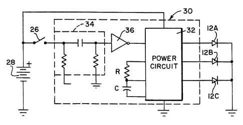
A diagram of a circuit for use in my present invention is show in
Fig. 3. This circuit includes three LEDs 12 as the light sources, a battery 28
and
a spring switch 26. This arrangement is controlled by a circuit 30.
The circuit 30 includes a monostable multivibrator 32 which is
5 triggered by a positive pulse. The switch 26 is connected to the
multivibrator
through a differentiator circuit 34 and an inverter 36. Closure of switch 26
creates a step of positive voltage on the input to the differentiator 34 and
opening the switch produces a negative step of voltage. The differentiator
converts these into a positive spike of voltage indicating closure of the
switch
10 and a negative spike when opening of the switch occurs. inverter 36 inverts
the
signal so that opening of the switch 26 produces a positive spike at the input
of the multivibrator which triggers the multivibrator into generating an
output
pulse having a predetermined period of time. This pulse is used to drive the
LEDs 12, which will illuminate once for a preset period determined by the
resistor R and capacitor C attached to the multivibrator.
If the monostable multivibrator 32 drives a low frequency oscillator
or flasher, such as a National Semiconductor LM3909, the LEDs 12 will flash
simultaneously at a low rate for the predetermined time period set by the
monostable 32. As an alternative, the monostable and/or the flasher can be
replaced with a VH215 LED flasher made by Vitelic Limited of Hong Kong. This
flasher can provide both predetermined and random flashes.
Fig. 4A illustrates a circuit that will cause multiple sequential
flashes after the spring switch 26 opens. When the spring switch 26 closes,
shown by a low level in the switch curve of Fig. 4B, the set input S on a
latch
or flip-flop circuit 42 is triggered. This produces a high level at the Q
output of
circuit 42 which enables a low frequency oscillator 44 which delivers pulses,
e.g., at the rate of 2Hz, to decade counter 46. A group of three OR gates 47
are coupled to selected outputs of the counter 46, e.g., counts 1, 4 and 7 may
be connected to gate 47A so that on those counts current will be applied to
LED
12A to light it. While not shown in the drawing for the sake of clarity,
counts
2, 5 and 8 are similarly connected to OR-gate 47B, while counts 3, 6 and 9 are
connected to gate 47C. Since the counts are in sequence, LEDs 12A, 12B and
CA 02294073 1999-12-21
WO 98/39983 PCTIUS98/04787
11
-12C will light in sequence three times. The 0 count is applied to inverter 49
and
used to reset the counter 46 and latch 42, which stops the sequence. If only
one sequence is desired, the 3 count is combined with an SEL signal in NAND
gate 41 to reset the counter and latch after the first sequence.
As soon as switch 26 closes, the latch 42 is in the set condition
and the sequence will start and continue as long as the switch is closed,
i.e., a
ground level on the S input will override the reset signal applied through the
capacitor 45 and the sequence will continue. This is acceptable with a spring
switch, but with a pressure switch or mercury switch, this could exhaust the
battery if the switch stays closed for too long.
When the switch 26 opens, the edge detector 34 produces a
positive spike. This spike is first applied to inverter 39 which generates a
reset
pulse that resets the latch 42 and the counter 46 to stop the sequence that
was
started by the closing of the switch. The spike from the edge detector is also
applied to delay circuit 43 which delays it so that the reset can be
accomplished. The output of delay 43 is then inverted by inverter 36 to
produce a negative spike that sets the latch again. As a result a new single
or
multiple sequence is initiated based on the opening of the switch. This
sequence will continue until completed by a reset signal to the latch from
gate
41 or inverter 49.
As shown in Fig. 4B, when the switch closes the sequence starts
as a result of the direct connection from the switch to the latch set input S.
Since the switch, if it is a spring switch, will likely open quickly after it
closes,
only a single sequence or three sequences, depending on the SEL signal, would
be visible. When the switch opens, this sequence is terminated as shown by
the small positive spike 48 in Fig. 4B. This then starts a new sequence which
continues for a predetermined or random period of time based on the opening
of the switch. Thus, when the switch is closed the LEDs sequence, and when
the switch opens a new terminating sequence begins.
Fig. 5A is a schematic of an alternative sequential lighting circuit
which could be implemented with as an integrated circuit. Shown in dotted line
50 in Fig. 5A is a circuit similar to a model 8533 integrated circuit made by
CA 02294073 1999-12-21
WO 98/39983 PCT/US98/04787
12
Sunwave Development Limited of Hong Kong. The 8533 circuit has a latch 52
which enables an oscillator 54 in response to an input from an edge detector
34.
Thus, whenever the input to the edge detector on pin 13 of the IC is grounded,
the IC starts a sequence. As with the arrangement in Fig. 4A, the oscillator
produces signals that are counted in divider 56. The resistor R connected to
the
oscillator 54 sets the frequency of the oscillator. The divider outputs are
decoded in decoder 58 and used to activate drivers 59 that illuminate LEDs 12.
The decoder 58 also resets the latch 52 after one or more sequences, depending
on the SEL switch input to pin 2 of the IC 50.
In order to implement the present invention, the IC 8533 is
modified to include the inverter 36 in the control logic after the edge
circuit 34
so the latch will be triggered (set) by the opening of the spring switch
instead
of the closing of the switch. In addition, an amplifier 57 and three reguiar
diodes 51 have been added. As long as the switch 36 is held closed, the
amplifier 57 puts a low level at the diodes 51 which creates a current path
from
the positive terminal of the battery 26, through each of the LEDs 1 2A - 1 2C
and
the diodes 51 to the low level at the output of the amplifier 58. This current
keeps the LEDs on for as long as the switch is held closed. This illumination
is
continuous, not flashing, and is shown in the first part of the curves of the
switch in Fig. 5B.
When the switch 26 opens, the edge detector 34 and the inverter
36 set the latch 52 so the sequence will began and run its course. At the end
of the sequence, the decoder 58 produces a reset signal that resets the latch
and stops the sequence. While this sequence may have a predetermined time,
it turns off based on the transition of the switch from "on" to "off" and not
from
"off" to "on." Thus, the illumination will occur on the foot that is being
raised
in the air and is most visible. This is the second half of the timing diagram
for
the lights in Fig. 5B.
It may be possible to incorporate the amplifier 57 and diodes 51
into a custom integrated circuit along with the rest of the elements. Also, it
should be noted that typically the switch, if it is a spring switch, will stay
closed
CA 02294073 1999-12-21
WO 98/39983 PCT/US98/04787
13
only a short period of time. Therefore, typically only the three flashes at
the end
of the timing diagram would be easily visible.
The circuit of Fig. 6A is another arrangement for carrying out the
invention that could be implemented as an integrated circuit 60. Parts which
perform a similar function in Fig. 6A to that in Fig. 5A are given the same
reference number. In this arrangement an oscillator, e.g., operating at 50kHz,
has its frequency set by an external resistor R. The oscillator is turned on
and
off by a trigger control 62 in response to the operation of switch 26.
When the switch 26 is closed the trigger control applies a signal to
decoder 58 to cause all of the driver transistors 59 to turn on and light the
LEDs
12. This is shown as portions A of the OUT curves in Fig. 6B. When the
switch opens, a sequence is started that first lights light 12A, (B in Fig.
6B) and
then lights LEDs 12B and 12C in sequence as shown by C and D in Fig. 6B.
Even if the switch opens and closes again during the sequence, i.e., E in Fig.
6B,
the sequence continues uninterrupted to its completion.
If the SEL switch is closed so that it is a low level, the sequence
will repeat once for a total of two as shown in the last half of the curves of
Fig.
6B.
To create the sequence the oscillator 54 generates the 50kHz signal
which is counted down in time base counter or divider 56. When the switch
opens the trigger control allows the down counter 64 to count the output of
the
time base divider. This count is decoded by decoder 58 and used to operate
driver transistors 59A-59C in sequence.
The details of an integrated circuit which could function as
integrated circuit 60 in Fig. 6A are shown in Figs 7A through 7E. A timing
diagram for this circuit is shown in Fig. 8.
The circuit of Fig. 7 has three states. In a first state the oscillator
54 is disabled by an EN signal and the system is waiting for a trigger signal
from
switch 26. When the IN signal from switch 26 goes low, the oscillator is
enabled by the trigger control and produces a KEY ON signal. This puts the
circuit in a second state.
CA 02294073 1999-12-21
WO 98/39983 PCTIUS98/04787
14
In the second state all of the LEDs are turned on while the switch
26 is closed. When the IN signal goes high, indicating that the switch has
opened, the KEY ON signal ends and a KEY OFF signal is generated. This puts
the circuit in a third state.
While in the third state the trigger control will not accept any more
IN trigger signals. If the SEL signal is high, the down counter 64 produces an
END signal after it counts from 3 to 1. If the SEL signal is low, the down
counter will produce an END signal only after it has counted down from 3 to 1
twice. The END signal puts the circuit back into the first state again to
await
another IN signal.
In particular at the end of a sequence with the circuit of Fig. 7A,
(i.e. the third state) a low level END signal is created. This is applied to
an input
of NAND-gate 71B which forms part of a flip-flop or latch circuit 71 in the
trigger control 62. As a result, the output of NAND-gate 71 B is forced high.
At the same time the switch 26 is open, so the signal IN is also high. Thus,
OR-
gate 92 has a high output which is applied to one input of NAND-gate 71 A. The
other input of NAND-gate 71 A receives the high output of NAND gate 71 B, so
the output of gate 71 A is low. This puts a low level on reset EN on line 90,
(Fig. 7B) which resets the time base counter 56 and locks up the oscillator 54
by inhibiting NAND-gate 93 (Fig. 7A). While, the low level on line 90 is also
applied to OR-gate 92, its output remains high because of the high IN level on
its other input. Similarly, the EN signal sets a flip-flop or latch 96
comprised of
gates 96A, 96B, so there is a!ow level at the output of gate 96B (Fig. 7B).
This
is state one of the circuit.
When switch 26 is closed, a low level signal IN is created at the
input to OR-gate 92 (Fig. 7A), which together with the low input to this gate
from line 90 (EN), creates a low input to gate 71A that sets the RS flip-flop
or
latch 71 so that the output of gate 71 A is high and so is the reset line 90.
Thus, the counter and oscillator are no longer blocked. This is state two of
the
circuit.
While in state two, the low IN signal is also applied to one input of
an OR-gate 95 along with the low signal from gate 96B (Fig. 7B). The result is
CA 02294073 1999-12-21
WO 98/39983 PCT/US98/04787
a low input to gate 98A of latch or RS flip-flop 98. This causes the output of
gate 98A to be high, which high level is applied over line 91 to one input of
NOR-gate 73 (Fig. 7C). This high signal is also clocked from line 93 to the Q
output of D flip-flop 72 by a signal F32 from gate 101 of time base counter 56
5 (Fig. 7D). The Q output of flip-flop 72 (97) is also applied to NOR gate 73
to
create a low signal KEY ON (Fig. 7C) that is at the output of NOR-gate 73
(Fig.
7C).
Referring to Fig. 7E, the KEY ON signal is inverted to a high level
by inverter 82. This high level is converted into low level signals by each of
10 gates 83A-83C, which in turn are converted into high level signals by
inverters
84A-84C and are used to turn on driver transistors 87A-87C. These transistors
cause the LEDs 12A -12C to light together for as long as the switch 26 is
closed. Signals OUT1, OUT2 and OUT3 at portion A in Fig. 8 are these signals.
Thus, it does not matter that the oscillator and counter are running. In this
15 state two, transistors 88 are off to save on battery power.
When switch 26 opens the IN signal goes high. See Fig. 8. This
allows latch 98 (Fig. 7B) to be reset by a version of the F32 signal from the
counter which has been delayed by having to pass through three inverters at
the
input to gate 98B. This allows D flip-flop 72 to reset first and eliminates a
race
condition. Resetting latch 98 makes the output of NAND-gate 98A low, which
in turn makes the KEY ON signal high and shuts off driver transistors 87A -
87C.
The low signal at the output of gate 98A is clocked to the output of D flip-
flop
72 by the next F32 signal, which is inverted in gate 75 to produce a high
signal
(Fig. 7C). This guarantees a low output of gate 76 which is inverted at gate
77
to provide a high KEY OFF signal. The other inputs to gate 76 are the signal
on
line 91 direct from gate 98A, F32 and F64. Thus the KEY OFF signal is low for
half a clock signal of F64, when all of the inputs to gate 76 are high. In
effect,
inverter 75 and NOR gate 76 combine to form a rising edge detector to produce
a KEY OFF pulse indicating that the switch has opened (Fig. 8).
As shown in Fig. 7D, the down counter 64, comprised of flip-flops
102 and 103, is reset through NAND-gate 112 by the KEY OFF signal, so the
counting by that counter, which sets the timing of the sequence, does not
start
CA 02294073 1999-12-21
WO 98/39983 PCT/US98/04787
16
until the switch opens some random time after it closed. The down counter 64
counts clock pulses from time base counter 56 when the switch 26 opens. It
counts down 3, 2, 1, 0. This is the third state of the circuit.
The state of down counter 64 is decoded by a series of NOR-gates
85A-85D, inverter 89 and NAND-gate 86. High outputs from the NOR-gates 85
are passed through NOR-gates 83 and NOR-gates 81 to transistors 88A-88C in
sequence according to the decoded signals, so as to drive the three LEDs in
sequence. The low signal from NOR-gate 83 also drives transistors 87A-87C
through inverters 84. Thus, during the sequence in the third state, both
transistors 87 and 88 drive the LEDs according to the following table.
STAGE 102 STAGE F32 OUTPUT
103
0 0 1 85A
1 0 1 85B
0 1 1 85C
1 1 X 85D
Counter stages 104 and 105 aid in determining whether there is
one sequences or two. These stages are reset by the KEY ON signal through
gate 110. The SEL signal of Fig. 7B is used to generate a SELECT signal from
inverter 79, which controls selector switch or multiplexer 99 (Fig. 7E) so as
to
generate the END signal either after a first sequence when the output of stage
104 is passed through selector 99 to form the END signal or after a second
sequence when the output of stage 105 is chosen by selector 99 to generate
the END signal. The END signal stops the sequence a predetermined time after
the switch opened to release the reset from Down Counter 64. It also returns
the circuit to state one to await the next closing of the switch 26.
If the footwear according to the present invention is equipped with
infrared or ultraviolet radiation light sources which are not readily visible
to the
human eye, they could be made visible by infrared or ultraviolet sensors or
goggles, e.g., as part of a game.
CA 02294073 1999-12-21
WO 98/39983 PCT/US98/04787
17
While the invention has been particularly shown and described with
reference to preferred embodiments thereof, it will be understood by those
skilled in the art that various changes in form and details may be made
therein
without departing from the spirit and scope of the invention.