Note: Descriptions are shown in the official language in which they were submitted.
CA 02294658 2000-01-07
D 97-1-084 PATENT
LAMP REFLECTOR WITH A BARRIER COATING OF A PLASMA POLYMER
1. Technical Field
The invention relates to electric lamps and particularly to plastic electric
lamp
reflectors. More particularly the invention is concerned with plastic body
lamp reflector with
a protective barrier layer.
2. Background Art
Headlamps used to be made from glass. The glass rarely reacted chemically with
the
lamp fill materials, and rarely if ever contributed, or outgassed materials
into the lamp
process. Automotive headlamps are now predominantly plastic, and the trend is
to apply
plastic to all vehicle lamps. To lower material costs, the shell material is
extended or filled
with less expensive materials, such mica or glass fiber. These filled resin
materials are
referred to as bulk molding compounds, or BMC. The fill material tends to
cause a rough
surface. The shell is then frequently coated with a liquid base coat to
prepare the reflective
regions to have a very high degree of smoothness. These smoothing materials,
such as an
acrylic urethane, flow over and fill in the crevices left in surface of the
shell. The base
coating material is expensive. The base coating can also be difficult to
properly apply, as it
tends to run, drip and splatter. Also, pits in the reflector shell can be
filled by the liquid, but
only dried to have surface skin. The interior liquid then erupts during
evacuation, leaving a
surface hole, and splattered material in the equipment. The base coating can
also be an
environmentally offensive material. The flow coating method is further
described in US
5,493,483. There is then a general need for reflector without a base coat. The
hard, smooth
base coat layer is then metallized, for example by vapor deposition or
sputtering of aluminum
on the shell interior to form a mirror like reflector. Although not strictly
necessary, the
reflective coating is then coated with an environmental sealer to limit or
stop water or other
materials from tarnishing the mirror surface. The sealer is commonly silicon
monoxide.
So called, no base coat reflectors have been developed. Relying on a
combination
controlled material formulation, tooling and processing, reflectors can be
made with a
sufficiently smooth surface that no base coat is needed, even if the resin
material includes
-1-
CA 02294658 2000-01-07
D 97-1-084 PATENT
fillers. The metallization layer is then applied directly on the formed resin
surface.
Elimination of the base coating is considered to be a significant improvement
in reflector
manufacture. Unfortunately, the resin materials can outgas solvents, or other
low molecular
weight resin constituents that then drift freely in the interior cavity. It is
a normal
characteristic of the raw plastic material to include mobile solvents or
similar mobile
components that enable the material to be soft and pliable for molding. After
molding, the
remaining solvent or similar material is superfluous and is normally baked out
or allowed to
outgas over time. These outgassed materials can condense on the interior
surfaces of the
vehicle lens, reflector or lamp. The condensed material fogs the light source,
the reflector and
the lens, and thereby reduces the effective light output. The outgasing
material can also
lessen the adhesion of the metallization layer, resulting in pin holes,
delaminations, wrinkles
and similar reflector defects, resulting in uncontrolled light, or glare
emitted from the lamp.
There is then a need for a no base coat vehicle headlamp reflector that
resists outgasing from
the shell material.
Headlamp reflectors made from filled bulk molding compound (BMC) have been pre-
baked at high temperatures to drive off outgasing materials. This takes time
and energy.
Alternatively, the reflectors have been flow coated with a base coating which
had the effect of
encapsulating the surface. Both these methods reduced the out-gassing of the
headlamp
reflectors at moderate operating temperatures of around 350 F. The new
smaller fog lamps
and headlamps use higher wattage bulbs and generate more energy thus raising
the maximum
operating temperatures found in the headlamp reflector systems to above 425 F,
resulting in
additional outgasing. The higher operating temperature forces a
reconsideration of the
material choices for headlamp reflectors. While base coating may continue to
work as a
sealer, base coating is still an expensive and environmentally challenging
process. The no
base coat headlamp design reduces the cost of forming a durable headlamp
reflector by
eliminating the base coat material, the coating equipment, the VOC emission
controls,
shortens the construction cycle time and reduces the labor required to run the
process.
Unfortunately, eliminating the base coat, eliminates the encapsulation that
protected the lamps
from the outgas materials. There is then a need for a practical means for
sealing shells from
outgasing.
-2-
CA 02294658 2008-12-11
A common protective surface coating for the aluminization layer is a plasma
deposition of silicon monoxide on the surface, such as Balzer's Protectyl BD
481 065
T or Dow Corning's 200 fluid 0.65 CST. The silicon monoxide protects the
aluminization from water attack, but does not protect against water from
condensing
on the surface or protect from outgassed resin material from collecting on the
reflector
as a haze. The silicon monoxide is relatively inexpensive to apply in terms of
material,
and in labor and equipment. There is then a need for an improved surface layer
material to eliminate out gassing from the support layers and to protect
metallized
reflector surfaces from the resulting condensations.
Disclosure of the Invention
An improved plastic reflector for use with an electric lamp may be formed
from a molded plastic reflector made from a bulk molded compound. The
reflector has
a first layer of a plasma polymerized material adhered to the inner surface
forming a
thin film that smoothes the surface of the bulk molded compound; a metal layer
of
deposited metal adhered to the first layer, and protective overcoating layer
adhered to
the deposited metal layer.
In accordance with an aspect of the invention, there is provided a lamp
reflector coated with plasma polymer comprising: a reflector shell having an
inner
wall including a reflective region; an inner barrier layer, formed as a first
plasma
polymer formed from siloxane, deposited at least on the inner wall of the
reflector
shell in the reflective region; a reflective layer, formed on at least the
inner barrier
layer; and a protective outer layer, formed over the reflective layer, in at
least the
reflective region, the protective layer being a second plasma polymer formed
from a
gas consisting essentially of elements selected from carbon, hydrogen and
oxygen.
Brief Description of the Drawings
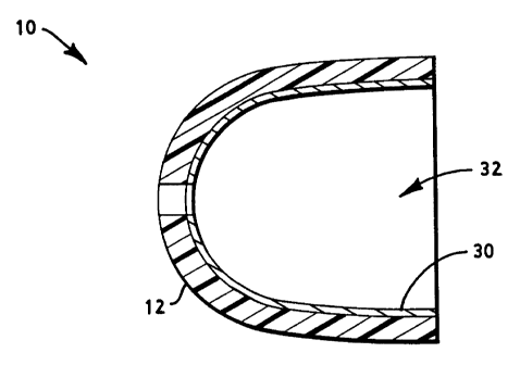
FIG. 1 shows a cross sectional view of a preferred embodiment of a lamp
reflector coated with plasma polymer of methanol.
FIGS. 2 to 10 shows a schematic cross sectional views of the layers of
preferred
embodiments of coated vehicle headlamp reflectors.
-3-
CA 02294658 2007-05-30
Best Mode for Carryinp- Out the Invention
FIG. 1 shows a preferred embodiment of a plastic lamp reflector coated with
barrier
layer formed as a plasma polymer layer. Like reference numbers designate like
or
corresponding parts throughout the drawings and specification. The barrier
coated reflector
is assembled from a plastic reflector shell 12, an inner barrier layer 14, a
reflective layer
18, an optional outer barrier layer 22 and additional protective layer 26. A
lens and related
finishing equipment for mounting, aiming and so forth may be added, as may be
convenient,
and as is generally known.
10 The reflector shell 12 may be made out of a plastic resin material such as
a bulk
molding compound (BMC) to have the general form of a hollow shell 12 with a
light
projection opening. The raw material for the reflector shell 12 includes a
resin material, and
may include one or more mobile components such as a solvent or similar
vaporizable
material, any one of which may outgas over time, depending on the temperature
and other
conditions of operation. The shell 12 includes an interior wall 30 defining an
enclosed
cavity 32. A portion of the interior wall 30, the reflective region, may be
formed to have or
include a surface coating to provide a highly reflective surface. The
preferred resin material
is a bulk molding compound. The preferred reflector is made according to the
no base coat
reflector formulation substantially as described in US 5,865,530, issued
February 2, 1999.
An inner barrier layer 14 is formed on the interior wall 30. The inner barrier
layer 14
may be made out of a material bondable to the shell 12 material and forming a
gas tight
barrier thereon. The preferred inner barrier layer 14 provides a lower surface
energy than
that of the inner wall of the reflector shell 12. This helps block through
migration of
materials, and enhances a smoother metallization layer. The preferred inner
barrier layer 14
has the general form of a thin layer, sufficiently solid to stop outgasing
material from the
reflector shell 12 (if any) from passing from the reflector shell 12 into the
enclosed cavity
32. Similarly, in a preferred alternative, the inner barrier layer 14 may have
sufficient
thickness 16 to deter the migration of oxygen into the reflector shell 12.
The preferred inner barrier layer covers all of the shell exposed to the
interior cavity,
to thereby prohibit any outgasing into the defined cavity. Practically, the
inner barrier layer
14 is likely to be effective roughly to the degree the interior wall 30 is
coated, and complete
effectiveness is desired, so a 100 percent coating is preferred. However, it
is understood that
a 90% coverage should yield about 90% reduction in outgassed materials, and
that may be
acceptable in some applications as comparison to the possible difficulties in
coating the
remaining 10 percent of the interior wa1130.
-4-
CA 02294658 2000-01-07
D 97-1-084 PATENT
The inner barrier layer 14 can also enhance the interior wall 30 smoothness,
and thereby
increase the reflectivity of the final lamp reflector. In the preferred
embodiment, the inner
barrier layer 14 is a plasma deposited layer of a plasma polymerized siloxane
type material.
The thickness 16 of the inner barrier layer 14 should be great enough to deter
outgasing from
the shell 12. It may also be preferred that it be thick enough to smooth over
defects in the
shell 12, or to deter penetration of oxygen into the shell 12. The thickness
16 should not be so
great as to undermine the optical formulation of the reflector. The preferred
inner barrier
layer 14 has a thickness 16 of from about 0.1 micron to about 0.5 micron.
The preferred inner barrier layer 14 is a plasma polymer of a siloxane
material, such as
Hexymethyldisiloxane (HMDSO), that is highly oxidized, (silicone dioxide with
reduce
carbon content). Tetramethyldisiloxane (TMDSO) is an alternative. There are
numerous
other others organosilicons that may work as well. The thickness of the film
that seems to
work the best on actual FN-10 vehicle lamp reflectors ranged from 0.1 microns
to 0.5
microns. This plasma polymer material is believed to be different from any
other coating that
has been deposited on automotive reflectors in the past. While a single inner
barrier layer 14
is described, it should be understood that multiple application of the same
material may be
performed at this station, or alternating layers of differing materials may be
applied. The
thickness of the inner barrier layer 14 should be great enough to deter
outgasing from the base
reflector. It may also be preferred that it be thick enough to smooth over
defects in the base
reflector, or to deter penetration of oxygen into the base reflector. The
inner barrier layer 14
improves the reflectivity of the reflective layer 18 by reducing outgasing
during the vacuum
process, allows the aluminum particles to wet the surface better (smoother)
and provides a
less contaminated surface (cleaner, and smoother).
The reflective layer 18 may be made with an aluminization layer, or similar
thin,
reflective metal layer. Sputtering is the preferred method for laying down the
reflective layer
18 on top of the inner barrier layer 14, but vapor deposition will work.
Sometimes silver is
used, and other metals may also be used. Aluminum is generally considered to
give the best
reflection for the least cost. Commonly the aluminum reflective layer 18 is
less than 1000
angstroms thick. The preferred aluminum thickness is between about 450 and 900
angstroms
with 600 believed to be the best. Ideally, the reflective layer 18 has a
smooth and highly
-5-
CA 02294658 2000-01-07
D 97-1-084 PATENT
reflective surface, providing a mirror like finish. The inner barrier layer 14
directly or
indirectly (for example where there is an intermediate layer, such as an
enhanced bonding
layer) supports the reflective layer 18. The reflective layer 18 may or may
not cover the
whole of the interior wall 30. In the event the reflective layer 18 does not
cover the whole of
the interior wall 30, it is still preferred that the inner barrier layer 14
cover the whole of the
interior wall 30. The reflective layer of its self acts as a barrier layer and
helps prevent
outgasing, and penetration by oxygen.
Applied over the reflective layer 18 may be an optional outer barrier layer
22. The
outer barrier layer 22, may also be formed as a plasma deposition a siloxane
material, again
such as silicone monoxide (Plasil). The outer barrier layer 22 is designed to
keep out water,
and thereby preserve the reflective layer 18 from tarnishing or corroding.
Silicone monoxide
is commonly plasma deposited to the reflective layer 18, as an outer barrier
layer 22. The
outer barrier layer 22 has a thickness 24 that is usually about 100 nanometers
thick and
extends at least over the reflective layer 18 at least in the reflective
region.
A protective layer 26 is now applied over the reflective layer 18, or the
optional outer
barrier layer 22, as the case may be. The protective layer 26 formed on the
reflective layer 18
provides a clear, protective and hydrophobic coating of the reflective layer
18. The protective
layer 26 may be made by plasma polymerization of a hydrocarbon gas or vapor
such as
methanol (methyl alcohol), but methane and numerous other hydrocarbon gases or
vapors
may be used. The plasma polymerization of these gases or vapors results in a
thin
hydrocarbon polymer aggregate layer formed over the outer barrier layer 22.
Again the
preferred protective layer 26 extends over the reflective region to protect
the optically
valuable portions of the mirror surface formed on the interior wall 30 of the
shell 12. The
preferred protective layer 26 has a thickness 28 from 10 to 1000 nanometers.
It is believed
that the deposited methanol works by depositing extra oxygen atoms to the
silicon mono-
oxide layer formed by the outer barrier layer 22. If the process time is
shortened, the
protective layer 26 is thinner, and the surface energy of the coated shell is
not sufficiently
changed to provide the desired anti-haze protection. If the process time is
lengthened, the
applied protective layer 26 degrades the outer barrier layer 22, resulting in
with poor water
resistance. The outer barrier layer 22 and the protective layer 26 are more
gas permeable than
-6-
CA 02294658 2008-05-07
the inner barrier layer 14 and the reflective layer 18, and therefore do not
add significantly
to the blocking of outgasing styrene or other components.
The preferred method of making the headlamp is to use a plasma deposition
machine
with single vacuum chamber, but one with multiple deposition stations. The
Applicant used
a Leybold DynaMet 4V machine, which has four plasma deposition stations in a
single
evacuated chamber. The machine was modified to have an additional diffusion
pump, (A
conventional rotary pump could be used.) at the second station to move the
polymer gas
through the vacuum, while holding a specific pressure. Another modification
was the
addition of hardware to handle the additional polymer gases at the second
station. A third
modification was the addition of control and software changes to run the
machine with the
proper sequencing and timing.
A particular advantage of the present machine structure is that the plasma
deposition
of the inner barrier layer 14 may be applied with the same jigging and in the
same device
that the reflective layer 18 is applied, and further, with the outer barrier
layer 22, and
protective layer 26. The process of manufacture is then to mold the plastic
reflector shell 12,
and the preferred molding process is according to the no base coat procedure.
The molded
plastic shell 12 is then positioned in a jig and transferred into a plasma
deposition chamber.
The preferred chamber has multiple subchambers separated by flexible dividers.
The
method of forming the plastic lamp reflector resistant to condensation thereon
had the
following steps:
First a no base coat headlamp reflector was formed from a BMC material
substantially according the process described in U.S. Patent No. 5,837,321,
issued
November 17, 1998. It should be understood that this is the preferred method
for getting a
smooth, reflective surface, but that other molding processes may be used, and
in general any
molded BMC or other reflector materials may be used in the present structure
and process.
To enhance the barrier film, the preferred no base coat reflector has a
surface composition
of about 57% carbon, 37% oxygen and 6% silicone. The shell 12 is molded to
have the form
of a thin wall defining a cavity with an interior wall 30. The molded shell 12
is then
positioned in a plasma deposition chamber. In one embodiment, the deposition
chamber had
a single evacuated cavity, with multiple deposition stations. For example, the
reflector shell
12 may be rotated in the evacuated chamber from station to station without
breaking the
vacuum.
-7-
CA 02294658 2000-01-07
D 97-1-084 PATENT
The first station provides for the loading and unloading of the plastic shell
12 into the
chamber. An initial vacuum may be provided by mechanical vacuum pumps and a
roots
blower.
The plastic shell 12 is then re-positioned in the second station, (first
subchamber) so
that its reflective region is treated with a reactive plasma deposition to
form an inner barrier
coating 14. At the second station an inner barrier layer 14 is then plasma
deposited on the
interior wall 30. The inner barrier layer 14 may comprise any of numerous
siloxane materials
that provide an enhancement of the surface and suppress gases from outgasing
through the
inner barrier layer 14, thereby protecting the reflective layer 18. The
preferred material for
the inner barrier layer 14 is a highly oxidized siloxane, such as HMDSO. A
deposition time
of about thirty seconds was found to provide the thinnest inner barrier layer
14 that
functioned. Deposition times longer than 1 minute resulted in surfaces that
were not glossy,
but instead had white haze defects, after metallization. While a single inner
barrier layer 14 is
described, it should be understood that multiple applications of the same
material may be
performed at this station, or alternating layers of differing materials may be
applied. The
thickness of this layer should be great enough to deter outgasing from the
plastic shell 12. It
may also be preferred that the inner barrier layer 14 be thick enough to
change the surface
energy to wet the reflective layer 18 better than the material of the
reflector shell 12. The
inner barrier layer 14 may also smooth over defects in the plastic shell 12,
or to deter
penetration of oxygen into the plastic shell 12. The thickness 16 should of
course not be so
great as to undermine the optical formulation of the reflector. The preferred
inner barrier
layer 14 is plasma deposited hexymethyldisiloxane (HMDSO) with a thickness 16
of about
from 0.1 to 0.5 microns.
The shell 12 is then rotated to the next subchamber passing the flexible
divider
therebetween. The divider is designed to keep the plasma materials from
passing between
adjacent subchambers. The plastic shell 12, now positioned in the second
subchamber, is
treated with a plasma deposition of the reflective layer 18 material. The
preferred reflective
material is aluminum. Aluminum is deposited over the inner barrier layer 14.
Sputtering is
the preferred method of applying the aluminum do to the higher energy
particles of aluminum
building a uniform film over the preceding inner barrier layer 14.
-8-
CA 02294658 2000-01-07
D 97-1-084 PATENT
The plastic shell 12 is then rotated again through a flexible barrier to a
third
subchamber for plasma deposition of a protective environmental outer barrier
18. The
preferred outer barrier 18 is a resulting silicone monoxide layer (tradename
Plasil), used to
shield the deposited aluminum from water and other oxidizing materials that
might tarnish the
aluminum over time. The process for creating the outer barrier 18 can be
described as
polymerization in a glow discharge, or the bonding of two or more monomers to
produce a
polymer. Electrons from the glow discharge electrode (cathode) on 4 kV
negative high
voltage move towards the substrate (anode) which are on ground potential. The
electrons
collide with the neutral gas molecules of the starting material (HMDSO
tradename Protectyl),
breaking chemical bonds and initiating the polymerization of the special
silicon oil.
Fragments which themselves are polymerized form polymerides that condense on
the surface
of the substrate. The resulting outer barrier 18 is an amorphous, organic,
environmental
protective coating which is very resistant to chemical influences and
withstands temperatures
of at least 200 C. The hexymethyldisiloxane which deposits different forms of
silicone
oxides on the surface after the polymerization of the material. The primary
chemical formed
over the sputtered aluminum forming the outer barrier 18 is silicone monoxide
with more
complex substance being silicone dioxide under certain processing conditions.
The film
however is relatively soft and not resistant to mechanical damage such as
scratches. The
outer barrier layer 22 is then plasma deposited on the aluminum reflective
layer 18. The
applicant's current process uses a radio frequency (RF) generator. The RF
source produces a
power density of 2,000 to 2,500 watts with-in working environment of 4.25
sq./ft. The
applicant is expecting to increase this to a radio frequency (RF) source
producing a power
density of about 3,500 to 6,000 watts with-in working environment of 4.25
sq./ft. While a
single outer barrier layer is described, it should be understood that multiple
application of the
same material may be performed at this station. The thickness of this outer
barrier layer 22
should be great enough to protect the aluminum from environmental damage due
to reaction
of water with the high purity aluminum. The preferred outer barrier layer 22
of silicone
monoxide has a thickness 24 of from 0.02 to 1.5 microns.
The plastic shell 12 remains in the same position for plasma deposition of a
protective
layer 26. The preferred protective layer 26 provides a clear, low surface
energy, hydrophobic
-9-
CA 02294658 2000-01-07
D 97-1-084 PATENT
material that is deposited on the outer barrier layerl8. The hydrophobic
material may be
formed by plasma deposition in the presence of a hydrocarbon gas, such as
methanol, to form
a plasma polymer layer. The plasma polymerization of methyl alcohol has been
found to
reduce the surface energy of the reflector and thereby resist condensation of
water vapor and
other materials. The shell 12 is then removed from the deposition chamber and
further
assembly, such the attachment of a lens and coupling hardware by known methods
is
completed. The plasma polymerized methanol provides a clear, protective and
hydrophobic
coating of the reflective layer 18, or the outer barrier layer 22, as the case
may be. It is
understood that described polymer layer may be used with base coated lamp
structures, and a
variety of sealing, metallization and other underlying layers, and still
benefit from the
disclosed condensation resistant polymer layer. The plasma polymerization
layer forms a
clear, low surface energy, hydrophobic surface layer on the aluminization
layer to prevent
condensations thereon surface plasma polymer layer of the aluminization layer
to a polymer
layer.
The chamber is then rotated to station 1, where the chamber is opened and the
reflector is
retrieved. The various depositions are preformed sequentially in a single
chamber, under
continuous evacuation. The process is then both clean and rapid. It should be
understood that
batch vacuum coating systems could be used to provide the various layers. It
is believed that
batch coating systems would be less efficient, due to the long deposition time
of 30 to 45
minutes. Batch coating is then a less preferred method of performing the
coating process. It
should be understood that completion of the headlamp reflector may proceed as
usual the
addition of a lens, support and adjustment hardware, exterior coatings and so
forth, as
generally known in the art. While there have been shown and described what are
at present
considered to be the preferred embodiments of the invention, it will be
apparent to those
skilled in the art that various changes and modifications can be made herein
without departing
from the scope of the invention defined by the appended claims.
FIG. 3 shows a schematic cross sectional view of the layers of a preferred
alternative
embodiment of a coated vehicle headlamp reflector. An alternatively preferred
structure is to
add an additional adhesion promoting layer of tetramethyldisiloxane (TMDSO).
Plasma
deposited directly on the on the reflector 12, the adhesion layer 34 of TMDSO
is then over
-10-
CA 02294658 2000-01-07
D 97-1-084 PATENT
coated with the inner barrier layer 14. The remaining reflective 18, outer
barrier 22 and
protective 26 layers then follow in sequence. The adhesion layer 34 is an
additional cost in
this design. It should be noted that the adhesion layer 34 of plasma deposited
TMDSO can be
used in this fashion as an additional layer in any of the following layer
patterns (FIG.s 4-9),
and for purposes of discussion may be considered as merely an alternative way
of preparing
the reflector 12 before proceeding to any of the subsequent layerings.
FIG. 4 shows a schematic cross sectional view of the layers of a preferred
alternative
embodiment of a coated vehicle headlamp reflector. Another alternative is to
formed the
outer barrier layer 22 from HMDSO using the relatively high plasma energy
level. On top of
the outer barrier layer 22 is formed a first environmental layer 36 which also
a plasma
deposition of HMDSO. The first environmental layer 36 is however, completed
with about
half the plasma energy level as used in forming the outer barrier layer 22.
While the starting
material, HMDSO is the same, the change in plasma energy, results in a
differing structure to
the layer which helps resist condensation on the final surface. It is
understood that the plasma
energy level may continuously adjusted from a high level to a lower level in
forming these
two layers, thereby effectively forming a single graded layer instead of two
distinct layers
(FIG. 5).
FIG. 6 shows a schematic cross sectional view of the layers of a preferred
alternative
embodiment of a coated vehicle headlamp reflector. The layered structure in
FIG. 6 is the
same as in FIG. 4(alternatively FIG. 5) with the outer barrier layer 22 of
HMDSO and first
environmental layer 36 of HMDSO. The layered structure is complete with a
further addition
of a second or final environmental layer 26 of a plasma polymer of methanol
that is applied
on top of the first environmental layer 36.
FIG. 7 shows a schematic cross sectional view of the layers of a preferred
alternative
embodiment of a coated vehicle headlamp reflector. Another alternative is to
coat the
reflector 12 with the inner barrier layer 14, and the reflective layer 18, and
then an
environmental layer 38 of a lower energy plasma deposition of HMDSO.
FIG. 8 shows a schematic cross sectional view of the layers of a preferred
alternative
embodiment of a coated vehicle headlamp reflector. The reflector 12 is coated
with the inner
barrier layer 14, the reflective layer 18, and then a layer of a plasma
polymer of methanol 26.
-11-
CA 02294658 2000-01-07
D 97-1-084 PATENT
This is a believed to be somewhat functional layered structure although the
methanol polymer
layer 26 may pass some chemical species that may effect the underlying
reflective layer over
time. Nonetheless the structure points out the independent utility of the
methanol polymer
layer 26.
FIG. 9 shows a schematic cross sectional view of the layers of a preferred
alternative
embodiment of a coated vehicle headlamp reflector. The reflector 12 is coated
with the
reflective layer 18, and then a layer of a plasma polymer of inethano126. This
is a believed to
be somewhat less functional as the outgasing protection of the inner barrier
layer has been
eliminated, and again the methanol polymer layer 26 may pass some chemical
species that
may effect the underlying reflective layer over time. Nonetheless the
structure again points
out the independent utility of the methanol polymer layer 26.
FIG. 10 shows a schematic cross sectional view of the layers of a preferred
alternative
embodiment of a coated vehicle headlamp reflector. The reflector 12 is coated
with the
adhesion layer 34, the reflective layer 18, and then a layer of a plasma
polymer of methanol
26. This is a believed to be somewhat functional layered structure as the
outgasing protection
has been partially achieved with the adhesion layer 34, and again the methanol
polymer layer
26 may pass some chemical species that may effect the underlying reflective
layer over time.
Nonetheless the structure again points out the use of the adhesion layer 34
and the
independent utility of the methanol polymer layer 26.
The applicant currently deposits the inner barrier layer on the outer surface
of the
reflective region. Due to the orientation of the masking, some of the inner
barrier layer wraps
around toward the backside (exterior), but for the most part little of the
remaining backside is
coated. None the less, 60 to 70 percent of the outgasing has been eliminated
by the inner
barrier layer.
Samples of an existing reflector (FN-10) were made with a no base coat
reflector
material, and coated with the inner barrier layer, the sputtered aluminum
layer, the outer
barrier layer (silicone monoxide layer such as Plasil) and the protective
layer such as plasma
reacted methanol. The plasma polymerized layer was formed by inserting
methanol into the
plasma chamber during plasma generation. The plasma fragmented and polymerized
the
methanol resulting in a thin polymer aggregation of differing methanol
segments.
-12-
CA 02294658 2000-01-07
D 97-1-084 PATENT
The inner barrier layer has been found to improve the reflectivity of the
overlaying
reflective layer due to the reduction in outgasing in the vacuum aluminization
process. The
outgasing material is believed to intermingle with and generally interfere
with the base
surface, the aluminization layer, and the surface of the aluminization layer.
Blocking the
outgasing then improves all of these aspects. The inner barrier layer also the
enhances the
wetting of the aluminum particles, resulting in smoother reflective layer. In
combination
these aspects provide a reflective layer with greater reflectivity. It has
been found by
photometry that the maximum number of candelas for the no base coat reflectors
coated with
the inner barrier layer was increased by 25 percent over the maximum intensity
in candelas
for similar no base coat headlamps made without the inner barrier layer. It is
evident that the
plasma deposited inner barrier layer of siloxane greatly increases the
reflectivity of the no
base coat headlamp reflectors. This much improvement in photometry performance
was not
anticipated for the no base coat reflectors with a barrier coating process.
The enhancement
coating brings the no base coat surface quality up to the same reflective
performance as the
ultraviolet cured conventional coating processes for automotive lighting.
Fog lamps similarly made with an inner barrier layer of plasma deposited
siloxane were
found to have a 50 to 60 percent reduction in haze material formed on the
reflective surface
subsequent to lamp completion. The plasma deposited siloxane forms a low
energy layer on
the surface of the plastic resin that is believed to block migration of the
resin component from
outgasing. It is evident that the plasma deposited inner barrier layer
substantially blocks
outgasing of material from the reflector shell.
From the initial testing, the siloxane barrier layer, decreases the out-
gassing and
enhances the reflectivity of the no base coat headlamp reflector BMC
reflectors. The barrier
technology has other of beneficial results. First, the inner barrier layer
reduces the out-
gassing of styrene used in the no base coat reflector during operation.
Second, barrier layer
provides an enhanced no base coat surface before the deposition of sputtered
aluminum by (a)
containing the out-gassing materials under the siloxane film, and (b) the
barrier layer allows
the aluminum particles to wet out the siloxane surface in a uniform manor, due
to suppression
of reactive molecules during deposition process, thus increasing the
specularity of the surface.
-13-
CA 02294658 2007-05-30
A third benefit of the inner barrier layer is the improved adhesion of the
aluminum to the no
base coat substrate.
The barrier layers (inner and outer) resist oxidation of the base material,
allowing
the no base coat material to perform at higher temperatures than would other
wise could be
obtained without the coating. The barrier technology inhibits oxygen from
combining with
the plastic's base chemistry at elevated temperatures to stop the degradation
of the structural
performance.
By way of further example, test lamps were made from a filled resin chosen for
no-
base coat reflector manufacture (BMC Inc. 324-series). Test lamps for NS body
fog lamps
were made. A thin layer of a siloxane (the actual material is unknown) was
plasma coated in
a vacuum on the reflector surfaces, at least in the regions to be metallized.
The reflectors
were plasma coated in a large volume, high energy chamber (Leybold DynaMetTM
4V). The
barrier film was deposited in about 35 seconds. A barrier layer of about
between 0.1 and 0.5
microns was deposited. The plasma coated reflectors were then metallized and
overcoated
by standard procedures. The resulting lamps were then tested according to four
different
vehicle manufactures material test specifications. These are stringent
durability tests for
heat, humidity, mechanical strength and so on. All of the barrier coated lamp
reflectors
passed all of the requirements of all of the manufacturers (per lab testing).
The barrier layer
has been found to reduce the haze formed on the reflector after the lamp has
been put into
operation by 50 to 60 percent. This haze was found in prior lamps to be the
result of resin
materials outgasing from the reflector shell, and then condensing on the
reflective surfaces.
The barrier layer has also been found to provide a positive effect on the
smoothness of the
reflector surface, particularly in reflectors made with no base coat. BMC
plastic materials,
such as the one for the no base coat reflector surfaces have been adequate for
some
purposes, but have not been as highly reflective as the best made base coated
reflector
products. One of the unexpected benefits of the barrier layer is that it has
been found to
block oxygen from passing into the plastic shell. This suggests plasma barrier
treatment of
other plastics to preserve them. This could be particularly useful in plastics
used in high
temperature environments, for example a less expensive plastic coated with a
barrier layer
could have the same or better performance than a more expensive but uncoated
high
temperature plastic. In one sampling,
- 14-
CA 02294658 2000-01-07
D 97-1-084 PATENT
the best reflector conditions were found to use the no base coat formulation
of BMC
formulation, the shortest inner barrier layer cycle time (40 seconds), a
moderately thin
reflective film of something more than 800 Angstroms thickness and with parts
preheated at
60 C for 2 hours. The disclosed dimensions, configurations and embodiments are
as
examples only, and other suitable configurations
-15-