Note: Descriptions are shown in the official language in which they were submitted.
CA 02294735 1999-12-31
WO 99/02092 PCT/US98/13988
ENDOVASCULAR SYSTEM FOR OCCLUDING ANEURISM
BACKGROUND OF THE INVENTION
The present invention deals with a system for
treating an aneurysm. More specifically, the present
invention deals with an occlusion system deployed in the
vasculature containing the aneurysm.
Several methods of treating aneurysms have
been attempted, with varying degrees of success. For
example, open craniotomy is a procedure by which an
aneurysm is located, and treated, extravascularly. This
type of procedure has significant disadvantages. For
example., the patient undergoing open craniotomy must
undergo general anesthesia. Also, the patient undergoes
a great deal of trauma in the area of the aneurysm by
virtue of the fact that the surgeon must sever various
tissues in order to reach the aneurysm. In treating
cerebral aneurysms extravascularly, for instances, the
surgeon must typically remove a portion of the patient's
skull, and must also traumatize brain tissue in order to
reach the aneurysm.
Other techniques used in treating aneurysms
are performed endovascularly. Such techniques typically
involve attempting to form a mass within the sac of the
aneurysm. Typically, a microcatheter is used to access
the aneurysm. The distal tip of the micro catheter is
placed within the sac of the aneurysm, and the
microcatheter is used to inject embolic material into
the sac of the aneurysm. The embolic material includes,
for example, detachable coils. The injection of these
types of embolic materials suffer from disadvantages,
most of which are associated with migration of the
embolic material out of the aneurysm into the parent
CA 02294735 1999-12-31
WO 99/02092 PCT/US98/13988
-2-
artery. This can cause permanent and irreversible
occlusion of the parent artery.
For example, when detachable coils are used to
occlude an aneurysm which does not have a well defined
neck region, the detachable coils can migrate out of the
sac of the aneurysm and into the parent artery.
Further, it is, at times, difficult to gauge exactly how
full the sac of the aneurysm is when detachable coils
are being injected. Therefore, there is a risk of
overfilling the aneurysm in which case the detachable
coils also spill out into the parent artery.
Another disadvantage of detachable coils
involves coil compaction over time. After filling the
aneurysm, there remains space between the coils.
Continued hemodynamic forces from the circulation act to
compact the coil mass resulting in a cavity in the
aneurysm neck. Thus, the aneurysm can recanalize.
Embolic agent migration is also a problem.
For instance, where a liquid polymer is injected into
the sac of the aneurysm, it can migrate out of the sac
of the aneurysm due to the hemodynamics of the system.
This can also lead to irreversible occlusion of the
parent vessel.
Techniques have been attempted in order to
deal with the disadvantages associated with embolic
material migration to the parent vessel. Some such
techniques, commonly referred to as flow arrest
techniques, typically involve temporarily occluding the
parent vessel proximal of the aneurysm, so that no blood
flow occurs through the parent vessel, until a
thrombotic mass has formed in the sac of the aneurysm
which helps reduce the tendency of the embolic material
to migrate out of the aneurysm sac. However, thrombotic
mass can dissolve through normal lysis of blood. Also,
CA 02294735 1999-12-31
WO 99/02092 PCT/US98/13988
-3-
in certain cases, it is highly undesirable to occlude
the parent vessel even temporarily. Therefore, this
technique is, at times, not available as a treatment
option. In addition, even occluding the parent vessel
may not prevent all embolic material migration into the
parent vessel.
Another endovascular technique for treating
aneurysms involves inserting a detachable balloon into
the sac of the aneurysm using a microcatheter. The
detachable balloon is then inflated using embolic
material, such as liquid polymer material. The balloon
is then detached from the microcatheter and left within
the sac of the aneurysm in an attempt to fill the sac of
the aneurysm and form a thrombotic mass in any area of
the aneurysm not ffilled by the detachable balloon.
However, detachable balloons also suffer disadvantages.
For example, detachable balloons, when inflated,
typically will not conform to the interior configuration
of the aneurysm sac. Instead, the detachable balloon
requires the aneurysm sac to conform to the exterior
surface of the detachable balloon. Thus, there is an
increased risk that the detachable balloon will rupture
the sac of the aneurysm.
SUMMARY OF THE INVENTION
An occlusion system treats an aneurysm in a
parent vessel. The parent vessel defines a lumen that
has a lumen wall. The aneurysm has a neck in
communication with the lumen. The occlusion system
includes a stent configured for deployment in the parent
vessel. The stent has at least a first portion and a
second portion. The first portion is permeable to blood
flow and is arranged such that, when the stmt is
deployed, the first portion is spaced from the neck of
the aneurysm. The second portion is less permeable to
CA 02294735 1999-12-31
WO 99/02092 PCT/US98/13988
-4-
blood flow than the first portion and is arranged such
that, when the stent is deployed, the second portion
overlies the neck of the aneurysm.
BRIEF DESCRIPTION OF THE DRAWINGS
Figure lA is a side view of~an occlusion
device deployed in a parent vessel and proximate an
aneurysm.
Figure 1B is a transverse cross sectional view
of the device shown in Figure lA.
Figure 2A is a side view of one embodiment of
the occlusion device shown in Figure lA.
Figure 2B is a side view of a second
embodiment of the occlusion device shown in Figure lA.
Figure 2C is a side view of a third embodiment
of the occlusion device shown in Figure lA.
Figures 3A-3D illustrate the application of a
covering material to an internal surface of an occlusion
device in accordance with the present invention.
Figures 4A-4C illustrate the application of
covering material to the outside surface of an occlusion
device in accordance with the present invention.
Figure 5 illustrates an another embodiment of
an occlusion device in accordance with the present
invention deployed proximate an aneurysm.
Figures 6A-6D illustrate deployment of the
occlusion device shown in Figure 5 in accordance with
one aspect of the present invention.
DETAILED DESCRIPTION OF THE PREFERRED EMBODIMENTS
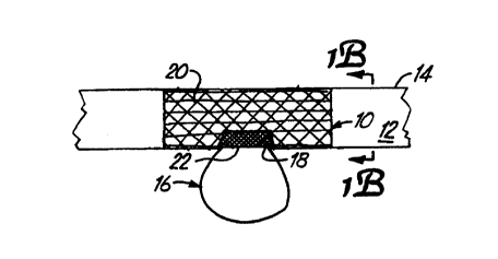
Figures lA and 1B show an occlusion device 10
deployed in the lumen 12 of a vessel 14 proximate an
aneurysm 16. In the preferred embodiment, occlusion
device 10 is a shape memory mesh device which is
delivered to the cite of aneurysm 16 in lumen 12 of
CA 02294735 1999-12-31
WO 99/02092 PCT/US98/13988
-5-
parent vessel 14. Device 10 is positioned to reside
over neck 18 of aneurysm 16.
Device 10, in the preferred embodiment, has a
first portion 20 which is formed of a material having
apertures therein so that the material is substantially
permeable to blood flow. Occlusion device 10 also
preferably includes a second portion 22 which is less
permeable to blood flow than portion 20. Occlusion
device 10 is deployed in vessel 12 such that second
portion 22 is disposed over, and substantially covers,
the neck 18 of aneurysm 16. With occlusion device 10 in
place, the hemodynamics of the system proximate
occlusion device 10 is, altered such that blood flow
through lumen 12 does not, in any meaningful quantity,
enter the sac of aneurysm 16. Instead, occlusion device
10 acts as a flow diverter which substantially contains
blood flow within lumen 12 of the parent vessel 14.
Since the blood within the aneurysm sac is not
circulating with the main blood flow, areas of
stagnation are created and the blood in the sac of
aneurysm 16 will thrombose.
In the preferred embodiment, occlusion device
10 is meant to remain in lumen 12 permanently. Thus,
occlusion device 10 provides a scaffolding for tissue
growth, eventually creating a new endolumenal surface
inside parent vessel 14 across neck 18 of aneurysm 16.
Occlusion device 10 can be deployed in lumen
12 of parent vessel 14 in any number of suitable ways,
including that described in greater detail with respect
to Figures 5-6D. However, in one preferred embodiment,
occlusion device 10 is a shape memory tubular device
which is capable of residing in a first state, but then
transitions to a second state in response to an
appropriate stimulus. For example, in one preferred
CA 02294735 1999-12-31
WO 99!02092 PCT/US98/13988
-6-
embodiment, occlusion device 10 is a shape memory
material which exists in a f lexible, and collapsed state
when it is below a transition temperature, but expands
into a more rigid configuration when it resides in an
environment above the transitig.n temperature. The
occlusion device 10 is delivered to the vascular region
of aneurysm 16 in the more flexible state, below its
transition temperature, so that it is soft and flexible
enough to pass through tortuous vasculature such as
intracranial vasculature. When occlusion device 10 is
below its transition temperature, it is preferably not
only flexible, but it is capable of being compressed
into even a lower profile to enhance its delivery.
Device 10 is preferably formed of wires having a
diameter and a configuration suitable to achieve the
delivery profile desired for any given application. The
device 10 is delivered through a catheter.
Once in place adjacent to the neck 18 of
aneurysm 16, occlusion device 10 is deployed from the
delivery catheter and the temperature is raised from a
point below the transition temperature, to a point above
the transition temperature. This can be accomplished,
for instance, by injecting warm saline, or simply by
letting occlusion device 10 warm to body temperature.
Once occlusion device 10 reaches the
transition temperature, it expands radially to a
predetermined diameter which approximates, and makes
contact with, the inner walls of parent vessel 14. The
delivery catheter is then removed and occlusion device
10 remains in place.
In accordance with one preferred embodiment of
the present invention, occlusion device 10 is formed
using small diameter nitinol wire filaments braided to
create occlusion device 10, and utilizing the shape
r
CA 02294735 1999-12-31
WO 99/02092 PCT/US98/13988
memory properties of nitinol to facilitate delivery and
deployment as described above. In one embodiment, the
nitinol filaments have a diameter of approximately 0.003
inches, or less. This gives occlusion device 10
sufficient flexibility and a very small size which
facilitates delivery of occlusion device 10 to
intracranial vasculature. tahere the device is used to
treat other ayes of the vasculature (such as an
abdominal aortic aneurysm), the wire will have a larger
diameter such as in a range of approximately 0.009" to
0.014". The size and shape of the apertures in
occlusion device 10, and the density of the filaments in
occlusion device 10 are preferably designed to meet the
specific application for which they are required.
Figures 2A-2C show three preferred embodiments
of occlusion device 10 in accordance with the present
invention. In Figure 2A, occlusion device 10 is similar
to that shown in Figure lA and includes first portion 20
and second portion 22. In the embodiment shown in
Figure 2A, second portion 22 is formed of a material
which is substantially impermeable to blood flow, such
as a suitable polymer material. Second portion 22 can
be woven into the braid of first portion 20 in occlusion
device 10, or it can be adhered to the inner or outer
surface of occlusion device I0, or it can be attached
using any other suitable attachment mechanism.
Figure 2B shows an alternative embodiment of
an occlusion device 24 in accordance with the present
invention. Occlusion device 24 is preferably formed of
braided filaments, such as braided nitinol filaments.
Occlusion device 24 includes first portion 26 and second
portion 28. As with occlusion device 10, first portion
26 is substantially permeable to blood flow, while
second portion 28 is less permeable to blood flow than
CA 02294735 1999-12-31
WO 99/02092 PCT/US98/13988
_8_
first portion 26. In the embodiment shown in 2B, first
portion 26 is formed of braided filaments having a first
pitch and thus defining apertures of a first size
therein. Second portion 28 is formed of braided
filaments having a second pitch, different from the
first pitch, and thus defining much smaller apertures
therein. In this way, simply by changing the pitch of
the braid along the length of occlusion device 24,
portions 26 and 28 can be formed.
Figure 2C shows yet another embodiment of the
occlusion device 30 in accordance with the present
invention. Occlusion device 30 includes first portions
32 and second portion 34. First portions 32 are formed
of a mesh-type material having apertures of a first
diameter defined therein. Portion 34 is formed of a
mesh-type material having apertures of a second
diameter, smaller than the diameters of the apertures in
the first mesh portions 32. Thus, portion 34 is less
permeable to blood flow than portion 32.
In all of the embodiments described herein
thus far, by providing an area over the neck 18 of the
aneurysm 16 which is less permeable to blood flow than
the remainder of the occlusion device, blood flow is
diverted away from the aneurysm 16, creating stagnant
areas inside the sac of the aneurysm 16. Blood thus
thrombose within the sac of the aneurysm 16 and cell
growth is promoted over the neck 18 of the aneurysm 16
along the surface of the occlusion device. In the
embodiments shown in Figures lA-2C, the aneurysm 16 may
first be filled with an embolic material, prior to
deployment of the occlusion device. However, in the
preferred embodiment, the occlusion devices are used
without filling the sac of the aneurysm 16, and simply
CA 02294735 1999-12-31
WO 99/02092 PCT/US98/13988
_9_
as a flow diverter avoiding the need for filling the
aneurysm 16.
Figures 3A-3D illustrate deployment of
occlusion device 36 in accordance with another preferred
embodiment of the present invention. In the embodiment
shown in Figure 3A, parent vessel 14 has a number of
perforating vessels 38 in communication therewith in a
region proximate aneurysm 16. Where occlusion device 36
is deployed in vasculature, such as abdominal
vasculature, the number of perforating vessels near
aneurysm 16 may be much smaller than perforating vessels
proximate an intracranial aneurysm. Such perforating
vessels are often important in that they supply blood to
the distal areas of the brain. Thus, an occlusion
device which contains a portion which may be
substantially impermeable to blood flow prior to
deployment in the vasculature adds difficulty to the
occlusion procedure in that the occlusion device must be
oriented quite precisely in order to ensure that the
covering region of the occlusion device is positioned
only over the neck of the aneurysm, and not over the
perforating vessels. This level of control over the
positioning of the occlusion device is particularly
difficult where instruments are in a size range required
for intracranial therapy.
Thus, Figures 3A-3D illustrate an embodiment
in accordance with the present invention in which the
portion of the occlusion device residing over the neck
of the aneurysm is made less permeable to blood flow
than the remainder of the occlusion device after the
occlusion device is deployed in the parent vessel.
Figure 3A illustrates that occlusion device 36,
throughout its entire length, is configured in such a
way so as to be significantly permeable to blood flow.
CA 02294735 1999-12-31
WO 99/02092 PCT/US98/13988
-10-
In other words, the apertures in device 36 are large
enough, along the entire length of device 36, to allow
blood flow to pass therethrough. Occlusion device 36 is
preferably deployed in lumen 12 proximate aneurysm 16 in
the manner described above with respect to occlusion
device I0, or in any other suitable manner.
Figure 3A also illustrates an optional step of
filling the sac of aneurysm 16 with embolic material
prior to performing subsequent steps in deploying device
36. For instance, microcatheter 40 can optionally be
deployed in lumen 12 and steered through the apertures
in occlusion device 36, through neck 18 of aneurysm 16,
and into the sac of aneurysm 16. Microcatheter 40 can
then optionally be used to inject embolic agents, or
other embolic material (such as coils, liquid polymer
material, or other embolic material), into the sac of
aneurysm 16 to promote thrombosis or simply to form a
mass within aneurysm 16.
Next, with reference to Figure 3B, an
inflatable member 42 is inserted in a collapsed position
through lumen 12 to the area proximate aneurysm 16.
Inflatable member 42 preferably has, releasibly fastened
to the exterior thereof, an occluding material or
occluding substance (covering material 44) which is
expandable and contractible with inflatable member 42.
Covering material 44 can be any suitable
covering material or substance suitable to application
to the inner surface of occlusion device 36. For
example, covering material 44 can be a suitable polymer
material sleeve which has adherent properties on, or an
adhesive applied to, the outer surface thereof. In any
case, inflatable member 42, along with covering material
44, is inserted within occlusion device 36.
CA 02294735 1999-12-31
WO 99/02092 PCT/US98/13988
-11-
Figure 3C illustrates that, once placed inside
occlusion device 36, inflatable member 42 is inflated to
a configuration which has an outer diameter that
approximates the inner diameter of occlusion device 36.
This drives covering material 44 into contact with the
inner surface of occlusion device 36. Again, covering
material 44 preferably has properties causing it to
adhere to the interior surface of occlusion device 36.
Figure 3D illustrates, that once covering
material 44 is deployed within occlusion device 36,
inflatable member 42 is deflated so that it separates
from covering material 44, leaving covering material 44
in place on the interior surface of occlusion device 36.
Inflatable member 42 is then removed from lumen 12
leaving occlusion device 36 covered only in the region
proximate neck 18 of aneurysm 16.
It will be understood that the longitudinal
placement of covering member 44 within lumen 12 using
the method described above is substantially less complex
than the precise placement of an expandable occlusion
device which is covered with a covering material prior
to deployment. This allows covering material 44 to be
carefully placed without covering any significant
perforating vessels 38 which perforate parent vessel 14
in the region of aneurysm 16. In addition, this
technique allows the longitudinal length of covering
material 44 to be easily adjusted prior to insertion.
However, covering member 44 can also be
configured to cover only a portion of the angular
periphery of device 36. In that case, covering member
44 is delivered to a region of device 36 overlying neck
18, thus achieving a similar configuration to that shown
in Figure 2A.
CA 02294735 1999-12-31
WO 99/02092 PCT/US98/13988
-12-
It should also be noted that coupling material
44, or the covering portion of any of the occlusion
devices previously described herein, can be coated with
substances having advantageous properties. For example,
the covering material can contain growth factors that
enhance cell growth (e. g. growth of endothelial cells)
at the neck of the aneurysm. This enhances the
possibility that a lumen wall will form over the neck of
the aneurysm.
Figures 4A-4C illustrate another feature
according to the present invention. Occlusion device 36
is covered after deployment in lumen 12, not from the
inside of occlusion device 36, but instead by accessing
the outer surface of occlusion device 36 from within the
sac of aneurysm 16, to provide a covering in that
specific area only.
After occlusion device 36 is deployed in the
manner described above, or another suitable manner,
microcatheter 46 is inserted through lumen 12 to the
region proximate aneurysm 16. Figure 4B illustrates
that microcatheter 46 is advanced such that its distal
tip 48 passes through the surface of occlusion device
36, through neck 18 in aneurysm 16 and into the sac of
aneurysm 16. A liquid embolic agent (such as an embolic
liquid polymer) or another suitable embolic material is
injected through microcatheter 46 to substantially fill
the sac of aneurysm 16. Since occlusion device 36 is
formed of a material substantially permeable to blood
flow, as the sac of aneurysm 16 is filled with embolic
material, the blood driven from the sac of aneurysm 16
exits through neck 18 and returns to the normal blood
flow through lumen 12.
Once inserted within the sac of aneurysm 16,
the embolic material thickens (or changes phase) and
CA 02294735 1999-12-31
WO 99/02092 PCT/US98/13988
-13-
fills the sac of aneurysm 16. As embolic material 50 is
injected within the sac of aneurysm 16, it eventually
fills the sac of aneurysm 16 and advances to the neck i8
where it encounters the outer surface of occlusion
device 36. The embolic material fills the interstices
of the wall of the occlusion device 36 in the region
adjacent neck 18 of aneurysm 16 and effectively covers
that portion of occlusion device 36. Microcatheter 46
is then removed and occlusion device 36 is left in
place, as shown in Figure 4C. Occlusion device 36 is
covered by the embolic material behind it in the
aneurysmal sac. Thus, the covering over the wall of
occlusion device 36 is specifically located at the neck
18 of aneurysm 16. This effectively inhibits accidental
occlusion of perforating vessels 38.
Figure 5 illustrates another embodiment of an
occlusion device 52 in accordance with the present
invention. Occlusion device 52 is illustrated in lumen
54 of a vessel 56 which has a first leg portion 58 and
a second leg portion 60, each of which define adjoining
lumens. Aneurysm 62 is located at the portion of vessel
54 where leg 58 joins leg 60. Aneurysm 62 includes a
neck portion 64 which communicates with lumen 54.
In the embodiment shown in Figure 5, occlusion
device 52 includes first portion 66 and second portion
68. First portion 66 is similar to the first portion 20
of occlusion device 10 shown in Figure lA, in that it is
formed of a material, braid, mesh, or other substance,
which has apertures therein which are large enough to be
substantially permeable to blood flow. Portion 68, on
the other hand, is less permeable to blood flow than
portion 66 and may be substantially impermeable to blood
flow. In one embodiment, portion 68 includes a covering
material which is attached to occlusion device 52 to
CA 02294735 1999-12-31
WO 99/02092 PCT/US98/13988
-14-
substantially cover neck 64 of aneurysm 62 when the
covering portion resides on portion 68 of occlusion
device 52 prior to deployment of occlusion device 52.
As with the embodiment shown in Figures 3A-3D, the
covering portion 68 can also be applied to occlusion
device 52 after occlusion device 52 is deployed in lumen
54. In the instance where the covering portion 68 is
applied to the interior surface of occlusion device 52,
a bifurcated expandable element (or balloon) is
preferably used with the covering portion attached to an
appropriate region thereof so that it becomes applied to
cover the neck 64 of aneurysm 62.
In the embodiment shown in Figure.5, occlusion
device 52 substantially forms a bifurcated tube
including leg portions ?0 and 72 and trunk portion 73.
The angle defined by leg portions 70 and 72 is
preferably predetermined, and includes any desired angle
for the treatment of, for instance, terminal aneurysms
(i.e., basilar tip aneurysms).
As with the occlusion devices described above,
occlusion device 52 is preferably configured to have an
insertion configuration and a deployed configuration.
The occlusion device 52 transitions between the
insertion configuration and the deployed configuration
in response to a predetermined stimulus. In the
insertion configuration, occlusion device 52 is
preferably highly flexible and collapsed to a small
outer diameter such that it is easily maneuverable to
the location of aneurysm 62 within tortuous vasculature
{such as intracranial vasculature). Once the stimulus
is applied, occlusion device 52 expands to its deployed
configuration shown in Figure 5, wherein it assumes an
outer diameter which closely approximates the inner
r
CA 02294735 1999-12-31
WO 99/02092 PCT/US98/13988
-15- '-
diameter of lumen 54, and contacts the inner surface of
lumen 54 to be retained therein.
In one preferred embodiment, the stimulus is
simply the resilience of the occlusion device itself.
Thus, as the occlusion device 52 is emerges from a
delivery catheter, it is released such that it expands
to its deployed configuration.
Figures 6A-6D illustrate another preferred
system for deployment of occlusion device 52. In one
preferred embodiment, occlusion device 52 is formed of
shape memory wire with a transition temperature as
discussed above. Figure 6A indicates that delivery
catheter 74 is preferably moved to the region of
deployment of occlusion device 52 proximate aneurysm 62.
Occlusion device 52, in the insertion position, is then
removed from within catheter 74.
In the preferred embodiment, the wire forming
occlusion device 52 is nitinol, or other similar
temperature sensitive wire. The wire defining the
region where legs 70 and 72 join is preferably biased
outwardly. Thus, once occlusion device 52 is deployed
to the position shown in Figure 6A and has emerged from
catheter 74, occlusion device 52 assumes the shape
illustrated in Figure 6B.
The biased wire drives separation of leg
portions 70 and 72 from the position shown in Figure A
to the position shown in Figure 6B. However, the
remainder of occlusion device 52 remains in the
insertion (collapsed) position. With leg portions 70
and 72 spread as shown in Figure 6B, occlusion device 52
can be easily positioned into a vessel bifurcation prior
to assuming its fully deployed position.
Figure 6C illustrates that, once occlusion
device 52 is positioned as shown Figure 6B, the
CA 02294735 1999-12-31
WO 99/02092 PCT/US98/13988
-16-
physician then injects saline, or another suitable
solution, at or above the transition temperature, which
causes leg portions 70 and 72 and trunk portion 73 to
expand to have a predetermined outer diameter which
closely approximates~the inner diameter of legs 58 and
60 and vessel 56. Figure 6D illustrates occlusion
device 52 in the fully expanded and deployed position.
In another preferred embodiment, occlusion
device 52 deploys outwardly to the position shown in
Figure 6D simply by warming to body temperature.
As with the other embodiments of occlusion
devices described herein, occlusion device 52 can be
used in a treatment in which aneurysm 62 is filled with
embolic material, or it can be used alone, simply as a
flow diverter. In either case, blood flow is diverted
away from the aneurysm and blood thromboses in the
aneurysm. Further, cell growth is preferably promoted
over the neck of the aneurysm along the surface of
occlusion device 52.
In order to obtain different rates of
expansion or deployment of occlusion devices herein, a
number of methods can be used. For instance, wire
having substantially the same transition temperature,
but different heat conductivity properties, can be used
to form different occlusion devices. In that instance,
the occlusion device takes a longer or shorter time to
deploy because it conducts heat from the surrounding
environment more slowly or more quickly than other
occlusion devices made of other material. In yet
another embodiment, completely different types of
stimuli can be used for deploying the occlusion device.
The occlusion devices described herein can be
coated or lined with any suitable material such as
thromboresisting material, antiangiogenetic material
CA 02294735 1999-12-31
WO 99/02092 PCT/US98/13988
-17-
such as hyloronic acid or taxol (to reduce the
likelihood of in-stent remodeling of the vessel), or
angiogenetic material or growth factors. The growth
factors can include, for example, vascular endothelial
growth factor (VEGF), platelet derived growth factor
( PDGF ) , vascular permeability growth f actor ( VPF ) , basic
fibroblast growth factor (BFGF), and transforming growth
factor beta (TGF-beta).
Although the present invention has been
described with reference to preferred embodiments,
workers skilled in the art will recognize that changes
may be made in form and detail without departing from
the~spirit and scope of the invention.