Note: Descriptions are shown in the official language in which they were submitted.
CA 02294777 2000-01-04
WO 99/04840 PCT/SE98/00959
A DEVICE AT A PHARMACEUTICAL CONTAINER OR INHALER
Technical Field
The present invention relates to a device at a pharmaceutical container or in-
haler for preventing an easy pulling apart of two connected, mutually
rotatable members
having circular cross sections, at least in the connection areas.
Background of the Invention
It is of great importance that children do not easily get access to the
interior of a
container or bottle of pills or of an inhaler (which is of special relevancy
in the present
case), as the contents of such a container or inhaler can be dangerous for
children. An
inhaler may for example hold a nicotine containing ampoule, used to administer
nicotine
to a person, who is trying to abandon the habit of smoking cigarettes. The
nicotine is
very harmful for children.
When the two mutually rotatable members of the inhaler have been connected
or assembled (after an ampoule have been inserted therein), it shall
preferably be difficult
or even virtually impossible for a child to disconnect or disassemble the two
members by
pulling them apart, but at the same time it shall not be too cumbersome for an
adult to
disassemble and then assemble the two parts.
Some devices for accomplishing the above objectives are known, one example
being the one shown and described in NO-B-158 214, in which a bayonet-type
connec-
tion is used.
The object of the present invention is to obtain a design for the above
purpose,
which will be easy to handle for an adult but virtually impossible for a
child, at the same
time as it shall be sturdy and inexpensive to manufacture, for example in a
plastic mate-
rial.
The Invention
These and other objectives are according to the invention for a general case
obtained in
that a first member towards its end intended for connection with a second mem-
ber is provided with a groove extending in the circumferential direction,
that the second member towards its end intended for connection with the first
member is provided with at least one boss for engagement with the groove,
CA 02294777 2000-01-04
WO 99/04840 PCT/SE98/00959
2
that the first member is provided with at least one axial notch from the
groove
to the end of the first member, and
that the groove in the vicinity of each notch is provided with at least one
pri-
mary recess in the side in which the notch commences.
Normally, only one boss and one notch are provided, but an improved safety
can be obtained, if several bosses and notches with different pitches are
provided, so that
only one of several mutual positions of the two rotatable members is the
correct one for
pulling them apart.
By this design (with one boss and one notch) the two members may be easily
assembled or connected by pushing them together with the boss in the notch,
whereupon
they are turned in relation to each other with the boss in the groove. A
following attempt
to disconnect or disassemble the members by pulling them apart under
concurrent turn-
ing will not be successful, because the boss will be caught in the primary
recess.
The invention is especially directed to an inhaler, as mentioned above.
Hereby,
the first member may be a mouthpiece for the inhaler and the second member a
cap. The
groove may be arranged in an outer surface of an inner sleeve on the
mouthpiece and the
boss on an inner surface of an outer sleeve on the cap.
There is preferably a primary recess at either side of the notch for providing
a
"trap" for the boss at turning from either side. The "trapping" effect is
enhanced in that
each primary recess has a sharp side at the notch for preventing the boss from
reaching
the notch if a mutual pulling force is exerted on the mouthpiece and the cap.
The other
end of the primary recess is preferably sloping for facilitating a smooth
entrance of the
boss in the "trap".
Even if the boss is in the position for entering the notch from the groove, so
that
a pulling apart is possible, a certain resistance may be provided in that the
depth of the
notch is locally decreased, preferably towards its open end. This resistance
may prevent a
child from actually pulling the members apart.
In order to facilitate a controlled pulling apart of an adult there may be
external
marks on the mouthpiece and the cap for indicating when the boss is at the
notch. It has
been shown that such marks do not provide any guidance for a child.
It is preferred that the groove extends around the full periphery of the mouth-
piece, so that the two members can be freely rotated. A secondary recess,
preferably with
CA 02294777 2000-01-04
WO 99/04840 PCT/SE98/00959
3
sharp sides, can in such a case be provided substantially opposite the primary
recess(es)
for providing a secondary "trap" for the boss.
The boss is preferably generally rectangular in a top view but may have a
pointed side for facilitating entrance in the notch at assembly of the
mouthpiece and the
cap.
The Drawings
The invention will be described in further detail below reference being made
to
the accompanying drawings, in which:
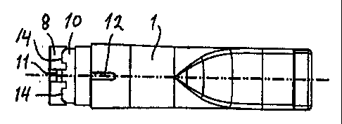
Fig 1 is a side view of an inhaler embodying the invention,
Fig 2 is a section through the inhaler along the line II-II in Fig 1,
Fig 3 is a section through the inhaler along the line III-III in Fig 2,
Fig 4 is a section to a larger scale through a cap of the inhaler according to
Fig 1,
Fig 5 is section through the cap along the line V-V in Fig 4,
Fig 6 is a perspective view of a mouthpiece of the inhaler according to Fig 1,
Fig 7 is a top view (to the same scale as Figs 1-3) of the mouthpiece
according
to Fig 6,
Fig 8 is a bottom view of the mouthpiece according to Fig 6, and
Fig 9 is a section to a larger scale through a detail of the mouthpiece
according
toFig7.
Detailed Description of a Preferred Embodiment
An inhaler embodying the invention includes a first member, namely a mouth-
piece 1, and a second member, namely a cap 2; the division line between the
two mem-
bers appears as a thicker line in Fig 1. A substance to be inhaled is to be
placed in the
form of an ampoule (not shown) or the like in the hollow interior of the
inhaler. With the
exception of the flattened end of the mouthpiece i to the left in Fig 1 for
comfortable
insertion into the mouth of a user, the mouthpiece 1 and the cap 2 both have a
circular
cross-section, especially in the region where they are connected to each
other, and they
may thus be turned in relation to each other.
The mouthpiece I and the cap 2 together form a tube when assembled. Accord-
ingly, the cap 2 has a central, circular opening 3 to the right in Figs 1-4,
through which
surrounding air is sucked in, whereas the mouthpiece 1 has a flattened or
substantially
*rg
CA 02294777 2000-01-04
WO 99/04840 PCT/SE98/00959
4
rectangular opening 4 to the left in Figs 1-3, through which air possibly
laden with sub-
stance from the ampoule, when fitted in the inhaler, is transferred to the
user's mouth.
Internally, the mouthpiece 1 and the cap 2 are provided with integral tubes 5
and 6, respectively, having sharpened ends 5' and 6', respectively, for
penetrating seals at
the ends of the mentioned, but not shown ampoule, when placed in the interior
of the
inhaler.
When assembled, the mouthpiece 1 and the cap 2 together form a generally
smooth exterior surface in the region for their connection. Also their
interior surface is
generally smooth in the connection region. This is accomplished in that the
cap 2 in its
connection region to the left in Figs 4 and 5 has an integral outer sleeve 7
with a smaller
wall thickness than the remainder of the cap 2. In the same way, the
mouthpiece 1 in its
connection region to the left in Figs 7 and 8 has an inner sleeve 8 with a
smaller wall
thickness than the remainder of the mouthpiece 1. The two sleeves 7 and 8
generally
have the same length and fit together for forming the connection shown in Figs
1-3.
However, the assembly and disassembly of the two members 1 and 2 can only
occur in
one mutual position thereof for providing a certain child-resistancy. The
invention is pri-
marily concerned with the means for obtaining this child-resistancy; these
means will now
be described.
The main means for obtaining the desired connection are a boss 9 in the outer
sleeve 7 of the cap 2 and a circumferential groove 10 in the inner sleeve 8 of
the mouth-
piece 1. With the exceptions mentioned below, the width and the depth of the
groove 10
are slightly larger than the axial dimension and the height, respectively, of
the boss 9, so
that the two members I and 2 may be rotated in relation to each other with the
boss 9 in
the groove 10. The groove 10 preferably extends the full turn around the
sleeve 8, but it
is also possible to have a groove that extends only a shorter distance.
There is only one exit from the groove 10, namely an axial notch 11 in the
inner
sleeve 8 of the mouthpiece 1. The width of this notch 11 exceeds the
circumferential
width of the boss 9. The end of the notch 11 opening into the groove 10 may
have the
same depth as the groove, but the notch depth may decrease towards the end of
the
notch 11 to the left in Fig 7. This is clearly illustrated in Fig 9, which is
an enlarged sec-
tion through the notch 11 and shows the bottom shape of the notch. By the
shallower
exit of the notch 11 a certain resistance is provided against the movement of
the boss 9 in
CA 02294777 2000-01-04
WO 99/04840 PCT/SE98/00959
the notch 11. In other words, a certain force is needed for pulling the
mouthpiece 1 and
the cap 2 apart, even if the rotational position with the boss 9 in front of
the notch 11 has
been found.
Assistance in this respect is provided in that the mouthpiece 1 and the cap 2
5 each have an external mark 12 (Fig 7) and 13 (Fig 5), respectively, which
marks are to be
put in front of each other for placing the boss 9 at the notch 11. It has been
shown that
this indication is not properly understood by small children.
At each side of the notch 11 there is a primary recess 14 in the forward edge
(to
the left in Fig 7) of the groove 10. Each recess 14 has a sloping side facing
away from
the notch I 1 and a sharp side at the notch with the result that if the
mouthpiece I and the
cap 2 when connected are mutually rotated while also pulled apart, the boss 9
will enter
the recess 14 along the sloping side but be stopped against the sharp side, so
that the
boss cannot find its way out through the notch 11.
At the side of the mouthpiece 1 generally opposite the notch 11 the groove 10
may be provided with a secondary recess 15 providing a further locking of the
two parts
mouthpiece 1 and cap 2 if they are rotated and pulled apart in an attempt to
separate the
two members from each other.
The side of the groove 10 opposite the notch 11 and the recesses 14 and 15 is
smooth, which means that the boss 9 can slide freely against this side when
the mouth-
piece 1 and the cap 2 are mutually rotated but not pulled apart.
As appears from Figs 4 and 5, the boss 9 may have bevelled edges and a
slightly
pointed end for facilitating entry into the notch 11 at assembly.
An important feature of the invention is the provision of the "trap"
constituted
by the primary recesses 14, and it has to be pointed out that several
practical alternatives
to the recesses shown and described are possible within the scope of the
claims.