Sélection de la langue

Search

Sommaire du brevet 2294777 

Énoncé de désistement de responsabilité concernant l'information provenant de tiers

Une partie des informations de ce site Web a été fournie par des sources externes. Le gouvernement du Canada n'assume aucune responsabilité concernant la précision, l'actualité ou la fiabilité des informations fournies par les sources externes. Les utilisateurs qui désirent employer cette information devraient consulter directement la source des informations. Le contenu fourni par les sources externes n'est pas assujetti aux exigences sur les langues officielles, la protection des renseignements personnels et l'accessibilité.

Disponibilité de l'Abrégé et des Revendications

L'apparition de différences dans le texte et l'image des Revendications et de l'Abrégé dépend du moment auquel le document est publié. Les textes des Revendications et de l'Abrégé sont affichés :

  • lorsque la demande peut être examinée par le public;
  • lorsque le brevet est émis (délivrance).
(12) Brevet: (11) CA 2294777
(54) Titre français: DISPOSITIF D'UN CONTENANT PHARMACEUTIQUE OU INHALEUR
(54) Titre anglais: A DEVICE AT A PHARMACEUTICAL CONTAINER OR INHALER
Statut: Durée expirée - au-delà du délai suivant l'octroi
Données bibliographiques
(51) Classification internationale des brevets (CIB):
  • A61M 15/00 (2006.01)
  • A61M 11/00 (2006.01)
  • A61M 15/06 (2006.01)
  • B65D 50/00 (2006.01)
(72) Inventeurs :
  • LEVANDER, GUSTAV (Suède)
  • FORSSELL, FREDRIK (Suède)
  • SJOGREN, JESPER (Suède)
(73) Titulaires :
  • MCNEIL AB
(71) Demandeurs :
  • MCNEIL AB (Suède)
(74) Agent: GOWLING WLG (CANADA) LLP
(74) Co-agent:
(45) Délivré: 2007-07-10
(86) Date de dépôt PCT: 1998-05-22
(87) Mise à la disponibilité du public: 1999-02-04
Requête d'examen: 2003-05-12
Licence disponible: S.O.
Cédé au domaine public: S.O.
(25) Langue des documents déposés: Anglais

Traité de coopération en matière de brevets (PCT): Oui
(86) Numéro de la demande PCT: PCT/SE1998/000959
(87) Numéro de publication internationale PCT: WO 1999004840
(85) Entrée nationale: 2000-01-04

(30) Données de priorité de la demande:
Numéro de la demande Pays / territoire Date
9702796-5 (Suède) 1997-07-25

Abrégés

Abrégé français

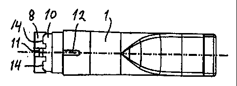
L'invention concerne un inhaleur pharmaceutique comprenant un embout buccal (1) et un capuchon (2) reliés l'un à l'autre de façon rotative. Pour assurer une sécurité pour enfant, l'embout buccal est doté d'une rainure circonférentielle externe (10) et le capuchon est doté d'une protubérance interne (9) destinée à s'emboîter dans la rainure. Une encoche axiale (11) s'étend de la rainure (10) jusqu'à l'extrémité de l'embout buccal et des éléments de retenue, sous forme d'évidements (14) sur la rainure, sont destinés à la protubérance et placés de chaque côté de l'encoche.


Abrégé anglais


A pharmaceutical inhaler has a mouthpiece
(1) and a cap (2), which are rotatably
connected to each other. For providing a certain
child-resistancy against disconnection, the
mouthpiece is provided with an external
circumferential groove (10), whereas the cap is
provided with an internal boss (9) for engagement
with the groove. There is an axial notch
(11) from the groove (10) to the end of the
mouthpiece, and "traps" for the boss in the form
of recesses (14) on the groove are provided at either side of the notch.

Revendications

Note : Les revendications sont présentées dans la langue officielle dans laquelle elles ont été soumises.


6
CLAIMS
1. A pharmaceutical container or inhaler device for preventing an easy pulling
apart of two connected, mutually rotatable members (1, 2) having circular
cross sections
where the members are connected.
characterized in
that a first member (1) towards its end intended for connection with a second
member (2) is provided with a groove (10) extending in a circumferential
direction,
that the second member (2) towards its end intended for connection with the
first
member (1) is provided with at least one boss (9) for engagement with the
groove (10),
that the first member is provided with at least one axial notch (11) from the
groove
(10) to the end of the first member, and
that the groove (10) in the vicinity of each notch (11) is provided with at
least one
primary recess (14) in the side in which the notch opens, and
that the first member (1) and the second member (2) are rotatable in relation
to one
another in a clock-wise direction as well as in an anti-clock-wise direction,
thus preventing
an easy pulling apart of said two members (1, 2)
2. A device according to claim 1, characterized in that the bosses and notches
are distributed with different pitch, when there is provided more than one
boss and notch.
3. A device according to claim 1, characterized in that there is provided one
boss (9) and one notch (11).
4. A device according to claim 3, the first member being a mouthpiece (1), the
second member being a cap (2) thereof, the groove (10) being arranged in an
outer surface
of an inner sleeve (8) on the mouthpiece (1) and the boss (9) being arranged
on an inner
surface of an outer sleeve (7) on the cap (2), characterized in that there is
the primary recess
(14) is at either side of the notch (11), each recess having a sharp side at
the notch for
preventing the boss (9) from reaching the notch if a mutual pulling force is
exerted on the
mouthpiece (1) and the cap (2).

7
5. A device according to claim 4, characterized in that the other end of each
primary recess (14) is sloping.
6. A device according to claim 4, characterized in that the depth of the notch
(11) is locally decreased for increasing the force needed to rotate the first
member (1) and
the second member (2) in relation to one another.
7. A device according to any of claims 4-6, characterized in that there are
external marks (12, 13) on the mouthpiece (1) and the cap (2) for indicating
when the boss
(9) and the notch (11) are engaged.
8. A device according to any one of claims 4-7, characterized in that the
groove (10) extends around the full periphery of the mouthpiece (1) and is
provided with a
secondary recess (15) with sharp sides substantially opposite at least one
primary recess
(14).
9. A device according to any one of claims 4-8, characterized in that the boss
(9) is generally rectangular in a top view but has a pointed side for
facilitating entrance in
the notch (11) at assembly of the mouthpiece (1) and the cap (2).

Description

Note : Les descriptions sont présentées dans la langue officielle dans laquelle elles ont été soumises.


CA 02294777 2000-01-04
WO 99/04840 PCT/SE98/00959
A DEVICE AT A PHARMACEUTICAL CONTAINER OR INHALER
Technical Field
The present invention relates to a device at a pharmaceutical container or in-
haler for preventing an easy pulling apart of two connected, mutually
rotatable members
having circular cross sections, at least in the connection areas.
Background of the Invention
It is of great importance that children do not easily get access to the
interior of a
container or bottle of pills or of an inhaler (which is of special relevancy
in the present
case), as the contents of such a container or inhaler can be dangerous for
children. An
inhaler may for example hold a nicotine containing ampoule, used to administer
nicotine
to a person, who is trying to abandon the habit of smoking cigarettes. The
nicotine is
very harmful for children.
When the two mutually rotatable members of the inhaler have been connected
or assembled (after an ampoule have been inserted therein), it shall
preferably be difficult
or even virtually impossible for a child to disconnect or disassemble the two
members by
pulling them apart, but at the same time it shall not be too cumbersome for an
adult to
disassemble and then assemble the two parts.
Some devices for accomplishing the above objectives are known, one example
being the one shown and described in NO-B-158 214, in which a bayonet-type
connec-
tion is used.
The object of the present invention is to obtain a design for the above
purpose,
which will be easy to handle for an adult but virtually impossible for a
child, at the same
time as it shall be sturdy and inexpensive to manufacture, for example in a
plastic mate-
rial.
The Invention
These and other objectives are according to the invention for a general case
obtained in
that a first member towards its end intended for connection with a second mem-
ber is provided with a groove extending in the circumferential direction,
that the second member towards its end intended for connection with the first
member is provided with at least one boss for engagement with the groove,

CA 02294777 2000-01-04
WO 99/04840 PCT/SE98/00959
2
that the first member is provided with at least one axial notch from the
groove
to the end of the first member, and
that the groove in the vicinity of each notch is provided with at least one
pri-
mary recess in the side in which the notch commences.
Normally, only one boss and one notch are provided, but an improved safety
can be obtained, if several bosses and notches with different pitches are
provided, so that
only one of several mutual positions of the two rotatable members is the
correct one for
pulling them apart.
By this design (with one boss and one notch) the two members may be easily
assembled or connected by pushing them together with the boss in the notch,
whereupon
they are turned in relation to each other with the boss in the groove. A
following attempt
to disconnect or disassemble the members by pulling them apart under
concurrent turn-
ing will not be successful, because the boss will be caught in the primary
recess.
The invention is especially directed to an inhaler, as mentioned above.
Hereby,
the first member may be a mouthpiece for the inhaler and the second member a
cap. The
groove may be arranged in an outer surface of an inner sleeve on the
mouthpiece and the
boss on an inner surface of an outer sleeve on the cap.
There is preferably a primary recess at either side of the notch for providing
a
"trap" for the boss at turning from either side. The "trapping" effect is
enhanced in that
each primary recess has a sharp side at the notch for preventing the boss from
reaching
the notch if a mutual pulling force is exerted on the mouthpiece and the cap.
The other
end of the primary recess is preferably sloping for facilitating a smooth
entrance of the
boss in the "trap".
Even if the boss is in the position for entering the notch from the groove, so
that
a pulling apart is possible, a certain resistance may be provided in that the
depth of the
notch is locally decreased, preferably towards its open end. This resistance
may prevent a
child from actually pulling the members apart.
In order to facilitate a controlled pulling apart of an adult there may be
external
marks on the mouthpiece and the cap for indicating when the boss is at the
notch. It has
been shown that such marks do not provide any guidance for a child.
It is preferred that the groove extends around the full periphery of the mouth-
piece, so that the two members can be freely rotated. A secondary recess,
preferably with

CA 02294777 2000-01-04
WO 99/04840 PCT/SE98/00959
3
sharp sides, can in such a case be provided substantially opposite the primary
recess(es)
for providing a secondary "trap" for the boss.
The boss is preferably generally rectangular in a top view but may have a
pointed side for facilitating entrance in the notch at assembly of the
mouthpiece and the
cap.
The Drawings
The invention will be described in further detail below reference being made
to
the accompanying drawings, in which:
Fig 1 is a side view of an inhaler embodying the invention,
Fig 2 is a section through the inhaler along the line II-II in Fig 1,
Fig 3 is a section through the inhaler along the line III-III in Fig 2,
Fig 4 is a section to a larger scale through a cap of the inhaler according to
Fig 1,
Fig 5 is section through the cap along the line V-V in Fig 4,
Fig 6 is a perspective view of a mouthpiece of the inhaler according to Fig 1,
Fig 7 is a top view (to the same scale as Figs 1-3) of the mouthpiece
according
to Fig 6,
Fig 8 is a bottom view of the mouthpiece according to Fig 6, and
Fig 9 is a section to a larger scale through a detail of the mouthpiece
according
toFig7.
Detailed Description of a Preferred Embodiment
An inhaler embodying the invention includes a first member, namely a mouth-
piece 1, and a second member, namely a cap 2; the division line between the
two mem-
bers appears as a thicker line in Fig 1. A substance to be inhaled is to be
placed in the
form of an ampoule (not shown) or the like in the hollow interior of the
inhaler. With the
exception of the flattened end of the mouthpiece i to the left in Fig 1 for
comfortable
insertion into the mouth of a user, the mouthpiece 1 and the cap 2 both have a
circular
cross-section, especially in the region where they are connected to each
other, and they
may thus be turned in relation to each other.
The mouthpiece I and the cap 2 together form a tube when assembled. Accord-
ingly, the cap 2 has a central, circular opening 3 to the right in Figs 1-4,
through which
surrounding air is sucked in, whereas the mouthpiece 1 has a flattened or
substantially
*rg

CA 02294777 2000-01-04
WO 99/04840 PCT/SE98/00959
4
rectangular opening 4 to the left in Figs 1-3, through which air possibly
laden with sub-
stance from the ampoule, when fitted in the inhaler, is transferred to the
user's mouth.
Internally, the mouthpiece 1 and the cap 2 are provided with integral tubes 5
and 6, respectively, having sharpened ends 5' and 6', respectively, for
penetrating seals at
the ends of the mentioned, but not shown ampoule, when placed in the interior
of the
inhaler.
When assembled, the mouthpiece 1 and the cap 2 together form a generally
smooth exterior surface in the region for their connection. Also their
interior surface is
generally smooth in the connection region. This is accomplished in that the
cap 2 in its
connection region to the left in Figs 4 and 5 has an integral outer sleeve 7
with a smaller
wall thickness than the remainder of the cap 2. In the same way, the
mouthpiece 1 in its
connection region to the left in Figs 7 and 8 has an inner sleeve 8 with a
smaller wall
thickness than the remainder of the mouthpiece 1. The two sleeves 7 and 8
generally
have the same length and fit together for forming the connection shown in Figs
1-3.
However, the assembly and disassembly of the two members 1 and 2 can only
occur in
one mutual position thereof for providing a certain child-resistancy. The
invention is pri-
marily concerned with the means for obtaining this child-resistancy; these
means will now
be described.
The main means for obtaining the desired connection are a boss 9 in the outer
sleeve 7 of the cap 2 and a circumferential groove 10 in the inner sleeve 8 of
the mouth-
piece 1. With the exceptions mentioned below, the width and the depth of the
groove 10
are slightly larger than the axial dimension and the height, respectively, of
the boss 9, so
that the two members I and 2 may be rotated in relation to each other with the
boss 9 in
the groove 10. The groove 10 preferably extends the full turn around the
sleeve 8, but it
is also possible to have a groove that extends only a shorter distance.
There is only one exit from the groove 10, namely an axial notch 11 in the
inner
sleeve 8 of the mouthpiece 1. The width of this notch 11 exceeds the
circumferential
width of the boss 9. The end of the notch 11 opening into the groove 10 may
have the
same depth as the groove, but the notch depth may decrease towards the end of
the
notch 11 to the left in Fig 7. This is clearly illustrated in Fig 9, which is
an enlarged sec-
tion through the notch 11 and shows the bottom shape of the notch. By the
shallower
exit of the notch 11 a certain resistance is provided against the movement of
the boss 9 in

CA 02294777 2000-01-04
WO 99/04840 PCT/SE98/00959
the notch 11. In other words, a certain force is needed for pulling the
mouthpiece 1 and
the cap 2 apart, even if the rotational position with the boss 9 in front of
the notch 11 has
been found.
Assistance in this respect is provided in that the mouthpiece 1 and the cap 2
5 each have an external mark 12 (Fig 7) and 13 (Fig 5), respectively, which
marks are to be
put in front of each other for placing the boss 9 at the notch 11. It has been
shown that
this indication is not properly understood by small children.
At each side of the notch 11 there is a primary recess 14 in the forward edge
(to
the left in Fig 7) of the groove 10. Each recess 14 has a sloping side facing
away from
the notch I 1 and a sharp side at the notch with the result that if the
mouthpiece I and the
cap 2 when connected are mutually rotated while also pulled apart, the boss 9
will enter
the recess 14 along the sloping side but be stopped against the sharp side, so
that the
boss cannot find its way out through the notch 11.
At the side of the mouthpiece 1 generally opposite the notch 11 the groove 10
may be provided with a secondary recess 15 providing a further locking of the
two parts
mouthpiece 1 and cap 2 if they are rotated and pulled apart in an attempt to
separate the
two members from each other.
The side of the groove 10 opposite the notch 11 and the recesses 14 and 15 is
smooth, which means that the boss 9 can slide freely against this side when
the mouth-
piece 1 and the cap 2 are mutually rotated but not pulled apart.
As appears from Figs 4 and 5, the boss 9 may have bevelled edges and a
slightly
pointed end for facilitating entry into the notch 11 at assembly.
An important feature of the invention is the provision of the "trap"
constituted
by the primary recesses 14, and it has to be pointed out that several
practical alternatives
to the recesses shown and described are possible within the scope of the
claims.

Dessin représentatif
Une figure unique qui représente un dessin illustrant l'invention.
États administratifs

2024-08-01 : Dans le cadre de la transition vers les Brevets de nouvelle génération (BNG), la base de données sur les brevets canadiens (BDBC) contient désormais un Historique d'événement plus détaillé, qui reproduit le Journal des événements de notre nouvelle solution interne.

Veuillez noter que les événements débutant par « Inactive : » se réfèrent à des événements qui ne sont plus utilisés dans notre nouvelle solution interne.

Pour une meilleure compréhension de l'état de la demande ou brevet qui figure sur cette page, la rubrique Mise en garde , et les descriptions de Brevet , Historique d'événement , Taxes périodiques et Historique des paiements devraient être consultées.

Historique d'événement

Description Date
Requête pour le changement d'adresse ou de mode de correspondance reçue 2018-06-11
Inactive : Périmé (brevet - nouvelle loi) 2018-05-22
Accordé par délivrance 2007-07-10
Inactive : Page couverture publiée 2007-07-09
Lettre envoyée 2007-04-27
Inactive : Taxe finale reçue 2007-04-02
Préoctroi 2007-04-02
Inactive : Transfert individuel 2007-03-16
Lettre envoyée 2006-11-17
Un avis d'acceptation est envoyé 2006-10-03
Lettre envoyée 2006-10-03
Un avis d'acceptation est envoyé 2006-10-03
Inactive : Transfert individuel 2006-09-29
Inactive : Approuvée aux fins d'acceptation (AFA) 2006-09-07
Modification reçue - modification volontaire 2006-07-31
Modification reçue - modification volontaire 2006-05-26
Inactive : CIB de MCD 2006-03-12
Inactive : Dem. de l'examinateur par.30(2) Règles 2006-03-07
Lettre envoyée 2003-06-12
Requête d'examen reçue 2003-05-12
Exigences pour une requête d'examen - jugée conforme 2003-05-12
Toutes les exigences pour l'examen - jugée conforme 2003-05-12
Requête pour le changement d'adresse ou de mode de correspondance reçue 2000-03-07
Inactive : Page couverture publiée 2000-02-29
Inactive : CIB attribuée 2000-02-25
Inactive : CIB en 1re position 2000-02-25
Lettre envoyée 2000-02-10
Inactive : Notice - Entrée phase nat. - Pas de RE 2000-02-10
Demande reçue - PCT 2000-02-04
Demande publiée (accessible au public) 1999-02-04

Historique d'abandonnement

Il n'y a pas d'historique d'abandonnement

Taxes périodiques

Le dernier paiement a été reçu le 2007-04-19

Avis : Si le paiement en totalité n'a pas été reçu au plus tard à la date indiquée, une taxe supplémentaire peut être imposée, soit une des taxes suivantes :

  • taxe de rétablissement ;
  • taxe pour paiement en souffrance ; ou
  • taxe additionnelle pour le renversement d'une péremption réputée.

Veuillez vous référer à la page web des taxes sur les brevets de l'OPIC pour voir tous les montants actuels des taxes.

Titulaires au dossier

Les titulaires actuels et antérieures au dossier sont affichés en ordre alphabétique.

Titulaires actuels au dossier
MCNEIL AB
Titulaires antérieures au dossier
FREDRIK FORSSELL
GUSTAV LEVANDER
JESPER SJOGREN
Les propriétaires antérieurs qui ne figurent pas dans la liste des « Propriétaires au dossier » apparaîtront dans d'autres documents au dossier.
Documents

Pour visionner les fichiers sélectionnés, entrer le code reCAPTCHA :


Pour visualiser une image, cliquer sur un lien dans la colonne description du document. Pour télécharger l'image (les images), cliquer l'une ou plusieurs cases à cocher dans la première colonne et ensuite cliquer sur le bouton "Télécharger sélection en format PDF (archive Zip)" ou le bouton "Télécharger sélection (en un fichier PDF fusionné)".

Liste des documents de brevet publiés et non publiés sur la BDBC .

Si vous avez des difficultés à accéder au contenu, veuillez communiquer avec le Centre de services à la clientèle au 1-866-997-1936, ou envoyer un courriel au Centre de service à la clientèle de l'OPIC.


Description du
Document 
Date
(aaaa-mm-jj) 
Nombre de pages   Taille de l'image (Ko) 
Dessin représentatif 2000-02-29 1 3
Abrégé 2000-01-04 1 51
Description 2000-01-04 5 259
Revendications 2000-01-04 2 64
Dessins 2000-01-04 2 50
Page couverture 2000-02-29 1 38
Revendications 2006-05-26 2 70
Revendications 2006-07-31 2 70
Dessin représentatif 2007-06-22 1 6
Page couverture 2007-06-22 1 37
Rappel de taxe de maintien due 2000-02-08 1 113
Avis d'entree dans la phase nationale 2000-02-10 1 195
Courtoisie - Certificat d'enregistrement (document(s) connexe(s)) 2000-02-10 1 115
Rappel - requête d'examen 2003-01-23 1 112
Accusé de réception de la requête d'examen 2003-06-12 1 173
Avis du commissaire - Demande jugée acceptable 2006-10-03 1 161
Courtoisie - Certificat d'enregistrement (document(s) connexe(s)) 2006-11-17 1 105
Courtoisie - Certificat d'enregistrement (document(s) connexe(s)) 2007-04-27 1 105
PCT 2000-01-04 8 307
Correspondance 2000-03-07 1 36
Correspondance 2007-04-02 2 52