Note: Descriptions are shown in the official language in which they were submitted.
CA 02294805 1999-12-30
WO 99/01786 PCT/US97/21448
TILED RETROREFLECTIVE SHEETING
COMPOSED OF HIGHLY CANTED CUBE CORNER ELEMENTS
Field of the Invention
The present invention relates generally to cube corner retroreflective
sheeting that is capable of returning a significant percentage of incident
light at
1o relatively high entrance angles regardless of the rotational orientation of
the
sheeting about an axis perpendicular to its major surface.
Back~~round of the Invention
Retroreflective materials are characterized by redirecting incident light back
15 toward the originating light source. This property has led to the wide-
spread use of
retroreflective sheeting in a variety of conspicuity applications.
Retroreflective
sheeting is commonly applied to flat, rigid articles such as, for example,
road signs
and barricades to improve their conspicuity in poor lighting conditions.
Retroreflective sheeting is also used on irregular or flexible surfaces. For
example,
2o retroreflective sheeting can be adhered to the side of a truck trailer,
which requires
the sheeting to cover corrugations and protruding rivets, or the sheeting can
be
adhered to a flexible body portion such as a road worker's safety vest or
other such
safety garment.
Many conspicuity applications are governed by specific performance
25 standards for retroreflective sheeting. Manufacturers must demonstrate that
their
retroreflective sheeting is capable of meeting the relevant performance
standards to
be considered as a supplier in the marketplace. A body of standards exists
both for
describing retroreflection (see ASTM Designation E808-93b, Standard Practice
for
Describing Retroreflection) and for measuring retroreflectors, (see ASTM
3o Designation E809-94a, Standard Practice for Measuring Photometric
Characteristics of Retroreflectors).
Two known types of retroreflective sheeting are microsphere-based sheeting
and cube corner sheeting. Microsphere-based sheeting, sometimes referred to as
"beaded" sheeting, employs a multitude of microspheres typically at least
partially
CA 02294805 1999-12-30
WO 99/01786 PCTNS97/21448
embedded in a binder layer and having associated specular or diffuse
reflecting
materials (e.g., pigment particles, metal flakes or vapor coats, etc.) to
retroreflect
incident light. Dlustrative examples are disclosed in U.S. Patent Nos.
3,190,178
(McKenzie), 4,025,159 (McGrath), and 5,066,098 (Kult). Due to the symmetry of
beaded retroreflectors, microsphere-based sheeting exhibits relatively uniform
entrance angularity when rotated about an axis normal to the surface of the
sheeting. Therefore, the retroreflective performance of beaded sheeting is
relatively
insensitive to the orientation at which the sheeting is placed on the surface
of an
object. In general, however, microsphere-based sheeting exhibits relatively
low
to retroreflective efficiency. Beaded retroreflective sheeting typically
exhibits a total
light return of approximately 5% to 15% in an observation cone angled about
2°.
Cube corner retroreflective sheeting comprises a body portion typically
having a substantially planar base surface and a structured surface comprising
a
plurality of cube corner elements opposite the base surface. Each cube corner
15 element comprises three mutually substantially perpendicular optical faces
that
typically intersect at a single reference point, or apex. The base of the cube
corner
element acts as an aperture through which light is transmitted into the cube
corner
element. In use, light incident on the base surface of the sheeting is
refracted at the
base surface of the sheeting, transmitted through the respective bases of the
cube
2o corner elements disposed on the sheeting, reflected from each of the three
perpendicular cube corner optical faces, and redirected toward the light
source.
One aspect of many performance standards requires retoreflective sheeting
to return specified percentages of light incident on the face of the sheeting
at
various entrance angles. The total light return characteristic of a
retroreflective
25 sheeting as a function of the entrance angle of incident light is generally
referred to
in the art as the 'entrance angularity' of the sheeting. A retroreflective
sheeting
capable of returning a significant percentage of light incident at relatively
high
entrance angles can be characterized as having strong or wide entrance
angularity,
such as disclosed in the isobrightness curves in U.S. Pat. No. 4,588,258
30 (Hoopman).
CA 02294805 1999-12-30
WO 99/01786 PCT/US97/21448
By contrast, retroreflective sheeting with poor entrance angularity loses its
retroreflective brightness (total light return decreases) rapidly as the angle
of
incidence deviates from 0°. Moreover, entrance angularity typically
varies about a
360° range of orientation angles (orientational uniformity), requiring
proper
alignment of the retroreflective sheeting for each application. The entrance
angularity and orientationai uniformity of a retroreflective sheeting is a
significant
performance factor because it materially affects the ability of a driver to
see an
object such as a traffic sign or a safety barrier in poor lighting conditions
at various
orientations.
to The symmetry axis, also called the optical axis, of a cube corner element
is
the axis that forms an equal angle with the three optical surfaces of the cube
corner
element. Cube corner elements typically exhibit the highest optical efficiency
in
response to light incident on the base of the element roughly along the
optical axis.
The amount of light retroreflected by a cube corner retroreflector drops as
the
incidence angle deviates from the optical axis.
Cube corner elements offer the advantage of being significantly more
efficient retroreflectors than beads. The terms 'active area' and 'effective
aperture'
are used in the cube corner arts to characterize the portion of a cube corner
element
that retroreflects light incident on the base of the element. A detailed
teaching
2o regarding the determination of the active aperture for a cube corner
element design
is beyond the scope of the present disclosure. One procedure for determining
the
effective aperture of a cube corner geometry is presented in Eckhardt, Applied
Optics, v. 10, n. 7, July, 1971, pp. 1559-1566. U.S. Pat. No. 835,648
(Straubel)
also discusses the concept of effective aperture. At a given incidence angle,
the
active area can be determined by the topological intersection of the
projection of the
three cube corner faces onto a plane normal to the refracted incident light
with the
projection of the image surfaces for the third reflections onto the same
plane. The
term 'percent active area' is then defined as the active area divided by the
total area
of the projection of the cube corner faces. The retroreflective efficiency of
3o retroreflective sheeting is directly proportional to this percent active
area. The
maximum theoretical total light return of truncated cube corner elements
commonly
3
CA 02294805 1999-12-30
WO 99/01786 PCT/US97/21448
used in retroreflective sheeting is approximately 67%, while in practice cube
corner
retroreflective sheeting exhibits a maximum total light return of
approximately 35%,
due to sealing, front surface losses, and reflection losses at the cube faces.
Predicted total light return (TLR) for a cube corner matched pair array can
s be calculated from a knowledge of percent active area and ray intensity. Ray
intensity can be reduced by front surface losses and by reflection from each
of the
three cube corner surfaces for a retroreflected ray. Total light return is
defined as
the product of percent active area and ray intensity, or a percentage of the
total
incident light which is retroreflected. A discussion of total light return for
directly
to machined cube corner arrays is presented in U.S. Patent No. 3,712,706
(Stamen).
The light return profile of the basic cube corner element is inherently
asymmetric in nature. The breakdown of total internal reflection (TIR) is the
most
significant cause of this asymmetry in non-metallized cube corner
retroreflectors.
Coating the reflecting faces with a specular reflector substantially reduces
the
15 asymmetry in the reflection pattern. Metallized cube corner arrays,
however, are
typically not white enough for daytime viewing, such as on signing
applications.
The durability of the specular vapor coat may also be inadequate. Finally, a
portion
of the asymmetry is due in part to the asymmetric physical geometry of a cube
corner element. See Rityan, Optics of Corner Cube Reflectors, Soviet Journal
of
2o Optics Technology, v. 34, p. 195 (1967).
Retroreflective sheeting formed from cube corner elements exhibits a
corresponding asymmetry in its light return profile. By way of example, U.S.
Pat.
No. 3,712,706 to Stamen ('706 patent) discloses the three-lobed light return
profile
characteristic of a single cube corner element. Similarly, U.S. Pats. No.
4,202,600
25 (Burke) and 4,243,618 (Van Arnam) disclose an array of cube corner elements
having a plurality of zones with different angular orientations, such that the
total
light return retroreflected by cube corner retroreflective sheeting varies as
a
function of the entrance angle of the incident light and the orientation angle
of the
sheeting on the substrate. The six-lobed light return profile of Burke and Van
30 Arnam is characteristic of a matched pair of cube corner elements.
4
CA 02294805 1999-12-30
WO 99/01786 PCT/US97/21448
One approach to reducing the asymmetry of retroreflective sheeting is by
providing a retroreflective sheeting construction with a plurality of discrete
cube
corner arrays disposed at different orientations; a technique referred to in
the art as
'tiling'. Burke and Van Arnam patents disclose retroreflective sheeting having
arrays of conventional truncated cube corner elements with equilateral base
triangles tiled in a variety of different orientations on the surface of the
sheeting.
While the constructions suggested in these references address the issue of
asymmetry, the cube corner geometries disclosed in these references suffer a
rapid
decline in total light return at entrance angles greater than about
40°, since only a
1o small portion of the cubes are optically functional at a particular
orientation.
Therefore, retroreflective sheeting in accordance with these references do not
provide adequate total light return at high entrance angles for many
applications.
Another approach to accommodating this variation in entrance angularity is
to design retroreflective sheeting to have specific planes of improved
entrance
angularity. By way of example, the Hoopman patent discloses a retroreflective
sheeting wherein the cube corner elements are arranged in opposing matched
pairs
having their respective symmetry axes tilted toward one another. This geometry
results in a retroreflective sheeting with improved entrance angularity in a
plane
substantially coincident with the plane that contains the symmetry axes of the
cube
2o corner elements, identified as the X-axis plane, and also in a Y-axis plane
perpendicular to the X-axis plane. In use, the sheeting is preferentially
oriented on
the substrate such that these planes coincide with the planes in which light
will
become incident on the sheeting. By way of example, a preferred orientation
for the
sheeting on a road sign is to align the X-axis plane substantially parallel
with the
ground.
U.S. Patent No. 5,565,151 (Nilsen) discloses matched pairs of
retroreflective cube corner elements that are tilted or canted between more
than 1.0
degree and less than about 7.0 degrees in a negative direction. A section of
one of
the cube corner elements in the matched pair is removed, creating a smaller
element
3o which produces increased observation angle performance.
CA 02294805 1999-12-30
WO 99/01786 PCT/US97/21448
U.S. Patent Application Serial No. 08/5887,719 (Nestegard et al.), entitled
Dual Orientation Retroreflective Sheeting, discloses a retroreflective
sheeting with
alternating zones of cube corner arrays oriented such that their primary
planes of
entrance angularity are approximately perpendicular to one another.
Thus, there is a need in the art for a retroreflective sheeting that maintains
a
visibly useful total light return across a 360° range of orientation
angles, particularly
at entrance angles greater than about 40°. Additionally, there is a
need in the art for
a retroreflective sheeting having relatively small variations in total light
return
across a 360° range of orientation angles at higher entrance angles and
particularly
1o at entrance angles greater than about 40°.
Brief Summary of the Invention
Preferred cube corner retroreflective sheeting disclosed herein includes
highly canted cube corner elements tiled in two approximately perpendicular
15 orientations such that the sheeting maintains a visibly useful total light
return at all
orientation angles for entrance angles about 40°, and more preferably
about 50° and
most preferably about 60°. Thus, a cube corner retroreflective sheeting
is disclosed
that is relatively less sensitive to orientation when compared with existing
cube
corner retroreflective sheeting constructions. The preferred retroreflective
sheeting
2o maintains visibly useful total light return performance at high entrance
angles while
maintaining high total light return at lower entrance angles.
The retroreflective article comprises a substrate having a base surface and a
structured surface having a plurality of arrays of cube corner elements
opposite the
base surface. The arrays of cube corner elements comprise a first array of
cube
25 corner element opposing pairs and a second array of cube corner element
opposing
pairs. The symmetry axes of the cube corner elements in the first array are
tilted in
a backward direction at an angle measuring between about 12° and about
30° from
an axis normal to the base surface. The symmetry axes of the cube corner
elements
in the second array are likewise tilted in a backward direction by an angle
measuring
3o between about 12° and about 30° from an axis normal to the
base surface. The
second array of cube corner elements are oriented approximately perpendicular
to
CA 02294805 1999-12-30
WO 99/01786 PCT/US97/21448
the first array so that the retroreflective article provides a minimum total
light return
of about 5% across about a 360° range of orientation angles at an
entrance angle of
about 40°.
In an alternate embodiment, the symmetry axes of the cube corner elements
in the first array are tilted in a backward direction at an angle measuring
between
about 12° and about 30° from an axis normal to the base surface.
The symmetry
axes of the cube corner elements in the second array are likewise tilted in a
backward direction by an angle measuring between about 12° and about
30° from
an axis normal to the base surface. The second array of cube corner elements
are
io oriented approximately perpendicular to the first array so that the
retroreflective
article provides generally uniform total light return about a 360°
range of
orientation angles. In another embodiment, the cube corner elements in the
first and
second arrays are tilted in a backward direction at an angle measuring between
about 15.1 ° and about 30°.
The first array and the second array occupy roughly equal portions of the
structured surface of the retroreflective article. The cube corner elements
are
generally trihedral structures comprising three mutually perpendicular
triangular
optical faces that intersect at a peak and a triangular base. The triangular
base for
truncated cube corner elements is approximately coplanar with the base surface
of
2o the article. Alternatively, the cube corner elements can be "fixll cubes,"
e.g.
generally polygonal structures comprising three mutually perpendicular optical
faces
including two tetragonal optical faces and a third optical face that intersect
at a
peak, and a tetragonal base.
The symmetry axes of the cube corner elements in the arrays are more
z5 preferably tilted in a backward direction at an angle measuring between
about 14°
and about 20° from an axis normal to the base surface. The symmetry
axes of the
cube corner elements in the first and second arrays can be tilted the same or
a
different amount. The second array is preferably oriented at an angle between
about 85°and about 95° relative to the first array, and most
preferably at about 90E.
3o The retroreflective article exhibits a maximum theoretical total light
return
of approximately 100% percent in response to light incident on the article
along an
7
W . ._.. ... ....... _ . ....r.... ~.. ~_ ..._ __W.. _....w4w~ .._ " .. ., ..
_. .... _ . .
CA 02294805 1999-12-30
WO 99/01786 PCT/US97/21448
axis normal to the base surface of the article. The retroreflective article is
preferably capable of a minimum total light return of about 5%, and more
preferably
10%, across about a 360° range of orientation angles at an entrance
angle of about
40°, and more preferably at an entrance angle of about SO° and
most preferably at
an entrance angle of about 60°.
The cube corner element opposing pairs may or may not be physically
adjacent to each other, and can have the same or different retroreflection
pattern.
In one embodiment, the cube corner element opposing pairs are matched pairs
that
generate mirror image retroreflection patterns, such as elements that are
1o substantially identical but are rotated 180° relative to each other.
Retroreflection
patterns and reflection patterns refer to the configuration of reflected
light, typically
illustrated as isobrightness contours.
The substrate and the cube corner elements are preferably formed as a
unitary article from a light transmissible material having a refractive index
of
15 between 1.3 and 1.7. In one embodiment, the body layer of the
retroreflective
article comprises a light transmissible polymeric material having an elastic
modulus
less than about 7x10⁸ pascals, and the cube corner elements are formed from a
light
transmissible material having an elastic modulus greater than about 16xI0g
pascals.
The cube corner elements can incorporate minor deviations from perfect
20 orthogonality to thereby alter the light distribution in the emerging cone
of
retroreflected light.
The first and second arrays of cube corner elements can be coated with a
speculariy reflective substance. A sealing medium can be disposed adjacent to
the
first and second arrays of cube corner elements. The sealing medium is
preferably
25 bonded to the structured surface by a network of intersecting bonds that
define a
plurality of cells within which the cube corner elements are hermetically
sealed. The
sealing medium maintains an air interface with the structured surface such
that the
cube corner elements retroreflect according to the principles of total
internal
reflection.
3o A preferred mold assembly suitable for use in forming the retroreflective
sheeting and a method of making a retroreflective article using the mold are
also
CA 02294805 1999-12-30
WO 99/01786 PCT/US97/21448
disclosed. The mold assembly includes a substrate having a base surface and a
mold
surface opposite the base surface. The mold surface includes in roughly equal
proportions a first and a second array of cube corner element opposing pairs.
The
symmetry axes of the cube corner elements in the array are preferably tilted
in a
backward direction at an angle of between 15.1° and 30° from an
axis normal to the
base surface. The second array of cube corner elements is oriented
approximately
perpendicular to the first array. In an alternate embodiment, the first and
second
arrays of cube corner element opposing pairs are tilted by an angle of between
about 15.1 ° and about 20°. The method of making a
retroreflective article includes
forming a replica of the mold. The replica of the mold includes a mold surface
having a negative image of the mold. A retroreflective article is formed in
the mold
surface of the replica.
Brief Description of the Drawings
Fig. 1 A is a plan view of a portion of a retroreflective sheeting in
accordance with a preferred embodiment of the invention.
Fig. 1 B is a side view of a portion of the structured surface of the sheeting
of Fig. 1, taken along lines I-I.
Fig. 2 is a polar plot of the isobrightness contours of retroreflected light
for
2o a single array of the cube corner sheeting of Fig. 1 prior to tiling.
Fig. 3 is a polar plot of the isobrightness contours of retroreflected light
for
the cube corner sheeting of Fig. 1.
Fig. 4 is a plan view of a mold for forming retroreflective sheeting.
Fig. 5 is a plan view of the mold of Fig. 4 for forming retroreflective
sheeting according to an embodiment of the invention.
Fig. 6 is a polar plot of the isobrightness contours of retroreflected light
for
cube corner sheeting formed from the mold of Fig. 5.
Fig. 7 is a polar plot of the isobrightness contours of retroreflected light
for
cube corner sheeting formed from the mold of Fig. 5 arranged in a plurality of
3o generally orthogonal arrays.
9
CA 02294805 1999-12-30
WO 99/01786 PCT/US97/21448
Fig. 8 is a perspective view of an alternate embodiment of a cube corner
element.
Fig. 9 is a top plan view of the cube corner element of Fig. 8.
Fig. 10 is a side view of a mold for forming retroreflective sheeting
utilizing
the lamina of Fig. 8
Fig. 11 is a polar plot of the isobrightness contours of retroreflected light
for
cube corner elements tilted at 14° formed from the mold of Fig. 10.
Fig. 12 is a polar plot of the isobrightness contours of retroreflected light
for
cube corner elements tilted at 14° formed from the mold of Fig. 10 and
arranged in
to a plurality of generally orthogonal arrays.
Fig. 13 is a polar plot of the isobrightness contours of retroreflected light
for
cube corner elements tilted at 20° formed from the mold of Fig. 10.
Fig. 14 is a polar plot of the isobrightness contours of retroreflected light
for
cube corner elements tilted at 20° formed from the mold of Fig. 10 and
arranged in
a plurality of generally orthogonal arrays.
Detailed Description of the Preferred Embodiments
Preferred cube corner retroreflective sheeting disclosed herein is capable of
returning a significant percentage of incident light at relatively high
entrance angles
2o at all rotational orientations of the sheeting about an axis perpendicular
to its major
surface. The retroreflective sheeting comprises a first array of cube corner
element
matched pairs and a second array of cube corner element matched pairs. The
symmetry axes of the cube corner elements in the arrays are tilted in a
backward
direction at an angle measuring between about 12° and about 30°
from an axis
normal to the base surface. The first array of cube corner elements is
oriented
approximately perpendicular to the second array.
Also disclosed is a retroreflective article, preferably a retroreflective
sheeting that maintains a visibly useful total light return at all orientation
angles for
entrance angles up to 40°, and more preferably up to 50° or
60°. The structured
3o surface of the sheeting requires as few as two zones of cube comer element
arrays
preferably tiled along two orthogonal axes to accomplish this optical
objective, thereby
to
CA 02294805 1999-12-30
WO 99/01786 PCT/US97/21448
substantially reducing the effort and expense required to scale-up production
for such a
sheeting. Each zone includes an array of optically opposing cube corner
retroreflective
elements in which the optical axes are canted or tilted in a backward, or
negative,
direction by an angle between about 12° and about 30°, from an
axis normal to the
base surface of the sheeting, and more preferably between about 14° and
about 20°.
In describing preferred embodiments of the invention, specific terminology
will be used for the sake of clarity. However, the invention is not to be
limited to
the specific terms so selected. It is to be understood that each term so
selected
includes all technical equivalents that operate similarly. Additionally, while
the
1o present application discloses several embodiments of cube corner element
geometries, a wide variety of cube corner geometries, such as full cubes and
truncated cubes, can also be used. The base edges of adjacent truncated cube
corner
elements in an array are typically coplanar. The base edges of adjacent full
cube
corner elements in an array are not all in the same plane. One of ordinary
skill in the
optical arts will understand that varying degrees of canting and varying cube
sizes can be
used within the scope of the present disclosure. Insubstantial changes in cube
geometries calculated to yield substantially the same optical results should
also be
considered within the scope of the present application.
Retroreflective element opposing pairs refers generally to two cube corner
2o elements that generate opposing, although not necessarily identical,
retroreflection
patterns. The cube corner elements are not necessarily physically adjacent to
each
other. It is possible for opposing pairs to be physically separated on the
retroreflective article. Matched pairs generally refers to opposing pairs of
cube
corner elements that generate mirror image retroreflection patterns, such as
elements that are substantially identical but are rotated 180° relative
to each other.
Matched pairs are typically physically adjacent to each other.
Tiling the structured surface of the sheeting such that the cube corner arrays
in
the first zone are oriented about 75° to about 105°, and more
preferably about 85° to
about 95°, and more preferably about 90° to the cube corner
arrays in the second plane
3o provides a sheeting that maintains a visible total light return (TLR) at
all orientation
angles for entrance angles of up to 70°. Generally uniform total light
return about a
11
CA 02294805 1999-12-30
WO 99101786 PCTIUS97/21448
360° range of orientation angles refers to a minimum total light return
of about 5%, and
more preferably a minimum of about 10%, at an entrance angle of about
40°, and more
preferably up to about 50° and most preferably about 60°.
Additionally, when the
structured surface is composed of cube corner elements whose optical axes are
canted
within preferred angular ranges, the sheeting exhibits relatively small
variations in
theoretical total light return across a 360° range of orientation
angles, even at relatively
high entrance angles. Thus, the sheeting is less sensitive to orientation than
existing
retroreflective sheeting, while maintaining high levels of TLR at high
entrance angles. A
variety of methods are available for arranging the cube corner elements into
two
1o generally orthogonal zones.
Related U.S. Patent Applications filed on the same date herewith include:
Cube Corner Sheeting Mold and Method Making the Same (Atty. Docket No.
51946USA9A); Retroreflective Cube Corner Sheeting Mold and Sheeting Formed
Therefrom {Atty. Docket No. 53305USASA); Retroreflective Cube Corner
is Sheeting, Molds Therefore, and Methods of Making the Same (Atty. Docket No.
53318USA8A); Retroreflective Cube Corner Sheeting Mold and Method for
Making the Same (Atty. Docket No. 51952USA6A); and Dual Orientation
Retroreflective Sheeting (Atty. Docket No. 52303USA8B).
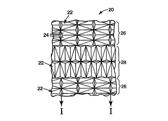
Fig. lA depicts a magnified view of a portion of the structured surface of a
2o preferred retroreflective sheeting 20. The structured surface includes a
plurality of
alternating zones 26, 28 which comprise two generally orthogonal arrays of
highly
canted cube corner elements 22. The cube corner elements 22 depicted in Fig. 1
A are
commonly referred to in the art as truncated cube corner elements, although
full cube
corner elements can also be used as will be discussed below. As shown, the
cube corner
25 elements 22 are disposed as optically opposing matched pairs in the zones
26, 28 on one
side of the sheeting. Each cube corner element 22 has the shape of a trihedral
prism
with three exposed planar faces 24. The dihedral angle between the cube comer
element faces 24 typically is the same for each cube corner element in the
array and
measures about 90°. The angle, however, can deviate slightly from
90° as is taught in
30 U.S. Patent No. 4,775,219 to Appledorn et al.
12
CA 02294805 1999-12-30
WO 99/0178b PCTNS97/21448
The structured surface of sheeting 20 comprises a plurality of alternating
zones
26, 28 of cube corner arrays disposed at approximately ninety degree
orientations. The
sheeting 20 preferably includes, in a repeating pattern, a first zone 26
including an array
of cube corner elements 22 disposed in a first orientation and a second zone
28 of cube
comer elements disposed in a second orientation. A suitable method for strip-
tiling
retroreflective sheeting is disclosed in U.S. Patent Serial No. 08/587,719
(Nestegard et
al.) entitled Dual Orientation Retroreflective Sheeting. Alternatively, the
sheeting 20
can be formed by a wide variety of tiling schemes that provide the first zone
26 generally
perpendicular to the second zones 28. The tiling schemes preferably minimizes
the
to number of deformed or otherwise optically inoperative cube corner elements.
Although
the first zone 26 includes an array of cube corner elements 22 formed by three
mutually
intersecting sets of grooves, cube corner elements can be formed with two
groove sets,
such as disclosed in Retroreflective Cube Corner Sheeting Mold and Method for
Making the Same (Atty. Docket No. 51952USA6A).
The individual cube corner elements 22 in the array define base triangle
included
angles of 72.60°, 72.60°, and 34.80°. Further, the cube
corner elements have a height
of about i0 microns to about 1000 microns. Second zone 28 extends
substantially
parallel to first zone 26 along the length of sheeting and includes an array
of cube corner
elements 22 substantially identical to the array disposed in first zone 26,
however the
2o array in the second zone is disposed at about a ninety degree orientation
relative to the
array in first zone 26.
As best seen in Fig. 1B, the symmetry axes 50 of opposing cube corner elements
22 are canted or tilted in a backward, or negative, direction by an angle that
measures
between about 12° and about 30°, from an axis 52 normal to the
base surface 54 of
the sheeting, and more preferably between about 14° and about
20°. This degree of
canting provides a cube corner element with one primary plane of entrance
angularity.
The axes are canted in a direction commonly referred to in the art as a
'backward' or
'negative' direction as discussed in U.S. Pat. No. 5,565,151(Nilsen). This is
to be
distinguished from canting in a 'forward', or 'positive' direction as
disclosed in U.S. Pat.
3o No. 4,588,258 (Hoopman).
13
CA 02294805 1999-12-30
WO 99/b1786 PCTIUS97/21448
Backward canted cube comer elements can also be characterized in that only
one included angle of the cube corner element base triangle is less than
60°. The other
two included angles measure at least 60°. By contrast, forward canted
cubes can be
characterized in that two of the included angles of the base triangle are less
than 60° and
a single base triangle included angle measures greater than 60°. It
will be understood
that the particular geometry discussed herein relate to preferred embodiments.
One of
ordinary skill will understand that varying degrees of canting and varying
cube sizes can
also be used.
The sheeting 20 can include a separate body layer 56 that includes a light
to transmissible polymeric material formed from a light transmissible material
having an
elastic modulus less than about 7x10⁸ pascals. The cube corner elements 22 can
then be formed from a different light transmissible material having an elastic
modulus greater than about 16x108 pascals. The cube corner elements 22
preferably are constructed from a thermoplastic or thermoset polymer. The
polymeric body layer 56 is preferably constructed from a thermoformable
polymer.
The body layer can be selected from the group consisting of ionomeric ethylene
copolymers, plasticized vinyl halide polymers, acid-functional ethylene
copolymers,
aliphatic polyurethanes, aromatic polyurethanes, other light transmissive
elastomers,
and combinations thereof. The cube corner elements 22 can be selected from the
2o group consisting of monofunctional, difunctional, and polyfunctional
acryiates or
combinations thereof. A specular reflector can be applied to the entire
surface of
the retroreflective sheeting 20 or along selected zones thereof.
Fig. 2 is an isobrightness contour depicting the total light return profile of
an
array of truncated cube corner elements as illustrated in zone 26 of the
retroreflective
sheeting of Fig. lA. The truncated cube corner elements were canted 17°
in a backward
direction formed from a material having in index of refraction of 1.59. The
highly
canted cube corner elements 22 of the first zone 26 provide one primary plane
of
entrance angularity.
As used herein, isobrightness contours plot the total light return obtained
from
3o cube comer elements. The concentric isobrightness curves represent the
predicted total
light return as a percentage of the light incident on the base surfaces of the
cube corner
14
CA 02294805 1999-12-30
WO 99/U1786 PCT/US97/21448
elements at various combinations of entrance angles and orientation angles.
Radial
movement from the center of the plot represents increasing entrance angles,
while
circumferential movement represents changing the orientation of the cube
corner
element with respect to the light source. The maximum retroreflectance is
represented
by the center point on the graph and concentric isobrightness contours
representing five
percent reductions in retroreflectance relative to the maximum, measured in
total light
return, are plotted.
Fig. 3 is an isobrightness contour depicting the total light return profile of
retroreflective sheeting 20 having a structured surface comprising truncated
cube corner
to elements 22 canted 17° in a backward direction, tiled in accordance
with the
embodiment depicted in Fig. 1, and formed from a material having an index of
refraction
of 1.59.
Table 1 contains the data presented graphically in Fig. 3 for such
retroreflective sheeting. The rotational orientation data of Table 1 is
limited to 0 to
90°, rather than a fill 360°, since the pattern repeats every
90°. The total light return
data for Table 1 does not include losses due to sealing, reflective coatings,
etc. Zero
degree orientation in Table 1 corresponds to the positive y-axis 58.
~_~ ..._.. ww.w.. ~ v.- ~.n..-.. d row . W_.~__ .. . ...... _. ~...~..~ m.. .
~.~..~.a~.~. ._...w~.~...M, .-.u .....~.....~.. ... .. M~.. .... ~ . _
....~_.. . .
CA 02294805 1999-12-30
WO 99/01786 PCT/US97/21448
N O N O ~D~ O M N
Gp O O ~O~n~1M ~1~O
O O O O O O O O
O O O O O O O O
~ OvN C1W O O~
'
O o0N o0t~V N o0
M N N ,-
O O O O O O O O
~ l~N .-~O .--.
O 00~OM N ~ t~~
M N -~~ ~ ~ 0 0
O O O O O O O O
N M OvO I~O~
O O 00~OM M ~ 2'~
M N .-.~ .-. O O
O O O O O O O O
wt00M M ~OI~U N
~ M M ~ N Q
r ,..
-. ..
O O O O O O O O
Wit'00Ov~ Ow0 w N
O o0n M N N '-v~
M N ,-..-. r.,
O O O O O O O O
~ 00N N O r-vDN
O o0N M N ~ Ovf~
M N N - -~O O
c~G O O O O O O O O
H
~ pvM t~~nN --O
O O o0O o0t~N O o0
M N N ~
O O O O O O O O
V'OvM t~~nN O -
O O 00O o0(~N O 00
M N N -- --~ O
O O O O O O O O
N
M O
O o0N N --~cTt~
M M N N ~ ~ --O O
O O O O O O O O O
c~
~ ooU N Ov~ ~nM
O ooI~M N N ~ ~n
~ ~ M N r,.--~~--~ ...O
O O O O O O O O O
~ 00M M ~ t~O~N
O O O ~ ~ M M ~ N N
.-. M N '-..-..-, O
O O O O O O O O
O
4.
~T~ N M O~O ~ O
v
O ~ ~ _
O M N ~ ~ O O
O O O O O O O O
N
U
U
O O O O O O O
N M ~Y~n~ t~
cd
N
16
CA 02294805 1999-12-30
WO 99/01786 PCT/US97/21448
Figs. 4-5 illustrate a preferred method of forming highly canted truncated
cube
corner elements on a plurality of laminae 90, such as disclosed in a U.S.
Patent
Application entitled Retroreflective Cube Corner Sheeting, Molds Therefore,
and
Methods of Making the Same (Atty. Docket No. 53318USA8A). First, second and
third groove sets 30, 38, 46, respectively, form a plurality of fully formed
truncated
cube corner elements 80a, 80b on the working surfaces of the plurality of
laminae
90. The cube corner elements 80a, 80b preferably extend across at least a
portion
of several laminae. Altering the location and groove angles of the grooves 46
of the
1o third groove set permits the manufacture of varying cube corner element
geometnes.
In the disclosed embodiment, cube corner elements 80a and 80b are
substantially identical in shape and size, but are disposed at 180°
orientations
relative to one another. Cube corner elements 80a have three mutually
perpendicular optical faces: two optical faces formed by faces 62 and 66, and
a third
optical face 86 corresponding to one surface of the third groove 46. The
bottom
edges of faces 62, 66 and 86 define base triangles having included angles ail,
(3Z, and
(33. Optical faces 62, 66 and 86 mutually intersect at a cube corner element
peak
88. Alternatively, the faces 62, 66, 86 do not necessarily need to intersect
in a
2o peak. Rather, a plateau or flat region can be formed that permits light to
be
transmitted through the retroreflective sheeting. Cube corner elements 80b
have
three mutually perpendicular optical faces: two optical faces formed by
surfaces 68
and 72, and a third optical face 82 corresponding to the opposite side of the
third
groove 46. The bottom edges of faces 68, 72 and 82 define base triangles
having
included angles ~1, (3z, and (33. Optical faces 68, 72 and 82 mutually
intersect at a
cube corner element peak 84.
In the embodiment described herein, base angle ~i~ measures
33.06°, base
angle ~i2 measures 73.47° and base angle (33 measures 73.47°.
Cube corner
elements with non-equilateral base triangles are commonly referred to in the
cube
3o corner arts as 'canted' cube corner elements. Canting cube corner elements
either
backward or forward enhances entrance angularity. Canting the cube corners in
the
17
CA 02294805 1999-12-30
WO 99/61786 PCT/US97/21448
backward direction elongates optical faces 62, 66 and reduces base angle (31.
Additionally, canting cube corner elements 80 in the backward direction
improves
the entrance angularity performance of the cube corner elements 80 in a plane
substantially parallel with common edges 64 and 70, especially for canting
greater
than about 12°. As will be discussed below, the more optically active
portions of
the cube corner elements 80 are generally concentrated along selected laminae.
This property has utility in retroreflective sheeting applications designed to
retroreflect light incident on the sheeting at high entrance angles.
Alternatively, the
base angles (31, X32 and (33 can all be different (scalene triangles), such as
disclosed in
l0 WO 96/42024 (Smith et al.). Additionally, the best planes of entrance
angularity
are not necessarily in the direction of cant, such as disclosed in WO 96/42025
(Smith et al.).
The cube corner elements are shaded to illustrate the more optically active
portions 89 of the cube corner elements at an entrance angle from about
0° to about
45°. The more optically active portions 89 of the cube corner elements
(cube
corner element segments) are concentrated adjacent to the third groove 46,
while
the less optically active portions 91 of the cube corner elements are
displaced from
third groove 46. The portion of a cube corner element on a single lamina that
has
three mutually perpendicular optical faces is referred to as a cube corner
element
2o segment. The portions of the cube corner elements removed typically do not
have
three mutually perpendicular optical faces, and consequently, are not cube
corner
element segments. The density of the more optically active cube corner element
segments are concentrated to provide enhanced optical properties.
The more optically active portions 89 can include less optically active
regions 87 located near the angles ~2, (33. A relatively small .portion of the
cube
corner elements SOa, 80b depicted in Fig. 4 are optically active. As the
entrance
angle decreases toward zero, the area of the more optically active portions 89
and
the effective aperture of that region decreases. At some point, the effective
aperture becomes a slit, diffracting light leaving the retroreflective article
primarily
3o in a plane containing the optical axis of the cube corner element and
perpendicular
to the slit. The diffraction within the slit aperture directs the reflected
light
is
CA 02294805 1999-12-30
WO 99/01786 PCT/US97/21448
primarily in one plane and degrades uniformity of the divergence profile of
the
retroreflected light, as discussed in ASTM E808-94.
Fig. 5 presents a top plan view of a plurality of optically opposing cube
corner element segments formed by removing a plurality of laminae (90c and
90f)
from the assembly depicted in Fig. 4. All of the laminae may or may not be the
same thickness. In an alternate embodiment, the laminae 90c, 90f can be
contiguous with one of the adjacent laminae, for example 90b and 90e,
respectively.
The portion of such contiguous laminae corresponding to 90c and 90f can then
be
removed by machining.
1o In one preferred embodiment, the plurality of cube corner element segments
depicted in Fig. 5 results from removing from the assembly those lanninae
which
have the less optically active portions of the cube corner element segments
disposed
on their respective working surfaces. The laminae removed from the assembly
90c,
90f are referred to herein as sacrificial laminae. The sacrificial laminae are
removed
from the assembly and the remaining laminae are reassembled in a suitable
fixture to
provide a structured surface comprising a plurality of cube corner element
segments
that correspond to the more optically active portions of the fully formed cube
corner elements formed in the working surfaces of the plurality of laminae in
the
original assembly. Because the less optically active portions of the cube
corner
2o element segments are removed, a retroreflector formed as a replica of this
mold can
exhibit substantially higher retroreflective efficiency than the
retroreflector formed
as a replica of the surface of the original assembly across a wide range of
entrance
angles. The laminae 90c, 90f can optionally be removed from the assembly prior
to
forming the third groove set 46. Formation of retroreflective sheeting from
the
mold of Fig. 5 is discussed below.
The optically active portions 89 of Figs. 4 and 5 illustrate a plurality of
cube
corner element matched pairs. It will be understood that the laminae 90 can be
arranged in a variety of configurations. For example, the laminae 90b, 90e,
90h can
be grouped together in a first sub-array and the laminae 90a, 90d, 90g grouped
3o together in a second sub-array, physically separated from the first sub-
array. The
cube corner elements on the laminae 90b, 90e, 90h can be optically opposing to
the
19
CA 02294805 1999-12-30
WO 99/01786 PCT/US97/21448
cube corner elements 90a, 90d, 90g, without being physically adjacent.
Retroreflective sheeting constructed as discussed above would preferably
include
four sub-arrays.
Fig. 6 is an isobrightness contour depicting the total light return profile of
retroreflective sheeting having a structured surface comprising cube corner
elements
according to Figs. 4 and 5 canted at 18° in a backward direction formed
from a material
having an index of refraction of 1.59. Again, the preferred highly canted cube
comer
elements provide one primary plane of entrance angularity.
Fig. 7 is an isobrightness contour depicting the total Iight return profile of
to retroreflective sheeting having a structured surface comprising cube comer
element
segments of Fig. 5 canted 18° in a backward direction, tiled in
accordance with the
embodiment depicted in Fig. I , and formed from a material having an index of
refraction
of 1.59.
Table 2 below, arranged in the same format as Table 1, contains the data
presented graphically in Fig. 7. The rotational orientation data of Table 2 is
limited to
0 to 90°, rather than a full 360°, since the pattern repeats
every 90°. The total light
return data for Table 2 does not include losses due to sealing, reflective
coatings, etc.
Zero degree orientation in Table 2 corresponds to the positive y-axis 58.
CA 02294805 1999-12-30
WO 99/01786 PCT/US97/21448
V1I"~'d'M !f00~O00
~ M ~
O O O O O O O
a-. O O O O O O O O
O 'rf00~'00O 00M
N 01tT~ C'~M O~~O
~hM N M ~--~- O O
O O O O O O O O
~ 00~Y~ V'N N W
00.-~t~,~..-.oo,-.
~ M N ~ ~-..~O O
O O O O O O O O
00!1'~OM M V100V1
M ~ ~
~t N - O O
O C O O C O O O
0000~'~'STO M ~
O '-'00 f~V'N Ov.-
pp ~ M N .-~,~.-.O O
O O O O O O O O
~ N O W ~ ~ t~O
'
_ _
~'M N M .--~r-.O O
O O O O O O cOO
~DM DO~ ~ ~ N v1
M N ~ ~
N ~ ~t .-.0 0
y O O O O O O O O
e~
~ rf'N N ~ O ~tM
O ~'O1(~V1(~M
~ O
~TM N N
O O O O O O O O
~ ~fiN N o0O ~tM
O ~-~O~C'",V~I~M O~~O
eYM N N -~~-O O
O O O O O O O O
U
~ M OON ~Dv N
O O
_ M N ~ ~ _
~h -.O O
O O O O O O O O
aS
_
O M 00~ ~O~ O
t
~CN M N _ ~ 0 0
~'1" M .-.
O O O O O O O O
i~t
G
O 00~ ~-~OvO ct~
O ~ ~ ~ O
." M N .-, O
O O O O O O O O
N ~ t~M M V'100~!1
O '
~f~fN
O O
O O O O O O O O
N
U
U
O O O O O O ~ O
td
N
21
CA 02294805 1999-12-30
WO 99/01786 PCT/US97/21448
Figs. 8-10 illustrate a lamina 100 containing a plurality of highly canted
full cube
corner elements, such as disclosed in a U.S. Patent application entitled Cube
Corner
Sheeting Mold and Method of Making the Same (Atty. Docket No. 51946USA9A),
suitable for use as a master mold to form full cube corner elements.
Alternatively,
the full cube corner elements disclosed in U. S. Patent Application entitled
Retroreflective Cube Corner Sheeting Mold and Sheeting Formed Therefrom (Atty.
Docket No. 53305USASA) can be used. Full cube corner elements have a higher
total light return than truncated cube corner elements for a given amount of
cant,
but the full cubes lose total light return more rapidly at higher entrance
angles. One
to benefit of full cube corner elements is higher total light return at tow
entrance
angles, without too large of a loss in performance at higher entrance angles.
For purposes of description, a Cartesian coordinate system can be
superimposed onto lamina 100. A first reference plane 124 is centered between
first
major surface 112 and second major surface 114. First reference plane 124,
referred to as the x-z plane, has the y-axis as its normal vector. A second
reference
plane 126, referred to as the x-y plane, extends substantially coplanar with
the
working surface of lamina 100 and has the z-axis as its normal vector. A third
reference plane 128, referred to as the y-z plane, is centered between first
end
surface 120 and second end surface 122 and has the x-axis as its normal
vector. It
2o will be appreciated that geometric attributes of the preferred embodiments
can be
described using coordinate systems other than the Cartesian reference planes
herein
described, or with reference to the structure of the lamina.
The laminae 100 contain a first groove set comprising a plurality of parallel
adjacent V-shaped grooves 130 disposed at an angle 81 as shown. At least two
adjacent grooves 130 are formed in the laminae 100, with each groove having a
first
and second groove surface 132, 134 that intersect at a groove vertex 133. At
the
edge of the lamina, the groove forming operation can form a single groove
surface
132. Importantly, the groove surfaces 132 and 134 of adjacent grooves
intersect
approximately orthogonally along a reference edge 136. Preferably this pattern
is
3o repeated across the entire working surfaces of the plurality of laminae
100.
22
CA 02294805 1999-12-30
WO 99/Oi786 PCT/US97/21448
The grooves 130 are formed by removing portions of the working surface of
the plurality of laminae using any of a variety of suitable material removal
techniques including precision machining techniques such as milling, ruling,
grooving and fly-cutting. Further, chemical etching or laser ablation
techniques can
also be used. In one embodiment, the grooves 130 of the first groove set are
formed in a high-precision machining operation in which a diamond cutting tool
having a 90° included angle is repeatedly moved transversely across the
working
surfaces of the plurality of laminae 100 along an axis that is substantially
parallel to
base surface 180. The cutting tool can be alternately be moved along an axis
that is
1o non-parallel to base surface 180 such that the tool cuts at a varying depth
across the
plurality of laminae 100. It will be appreciated that the machining tool can
be held
stationary while the plurality of laminae are placed in motion; any technique
having
relative motion between the plurality of laminae 100 and the machining tool is
contemplated. Thus, in a top plan view, reference edges 136 appear
perpendicular
i5 to the respective first reference planes 124 of the plurality of laminae
100.
A second groove set comprising a plurality of parallel adjacent V-shaped
grooves 138 is formed in the working surfaces of the plurality of laminae 100
with
the lamina disposed at an angle 82. At least two adjacent grooves 138 are
formed in
the working surface of the plurality of laminae 100 with each groove 138
having a
2o third and fourth groove surface 140, 142 that intersect at a groove vertex
141. At
the edge of the lamina, the groove forming operation can form a single groove
surface 140. Importantly, the groove surfaces 140 and 142 of adjacent grooves
intersect approximately orthogonally along a reference edge 144. Preferably
this
pattern is repeated across the entire working surfaces of the plurality of
laminae
25 100.
Grooves 138 are preferably formed at approximately the same depth in the
working surface of the plurality of laminae 100 as grooves 130 in the first
groove
set. Additionally, the grooves 138 in the second groove set are preferably
formed
such that the groove vertices 141 and reference edges 144 are substantially
coplanar
30 with the respective groove vertices 133 and reference edges 136 of the
grooves 130
in the first groove set.
23
CA 02294805 1999-12-30
WO 99/01786 PCT/L1S97/21448
A third groove set is formed that preferably includes at least one groove 146
in each lamina 100. The third grooves 146 define fifth and sixth groove
surfaces
148, 150 that intersect at respective groove vertices 152 along axes that are
parallel
to the first reference planes 124. Importantly, the third grooves 146 are
formed
such that fifth groove surfaces 148 are substantially orthogonal to first
groove
surfaces 132 and second groove surfaces 134. Formation of the fifth groove
surfaces 148 yields a plurality of cube corner elements 160.
Each cube corner element 160 is defined by a first groove surface 132, a
second groove surface 134, and a portion of a fifth groove surface 148 that
to mutually intersect at a point to define a cube corner peak, or apex I62.
Similarly,
sixth groove surface 150 is substantially orthogonal to third groove surfaces
140
and second groove surfaces 142. Formation of the sixth groove surface 150 also
yields a plurality of cube corner elements 170 in the working surface of
lamina 100.
Each cube corner element 170 is defined by a third groove surface 140, a
fourth
groove surface 142, and a portion of sixth groove surface 150 that mutually
intersect at a point to define a cube corner peak, or apex 172. Preferably,
both fifth
groove surface 148 and sixth groove surface 150 form a plurality of cube
corner
elements on the working surface of lamina 100. However, third groove 146 can
alternately be formed such that only fifth groove surface I48 or sixth groove
surface
150 forms cube corner elements. Additionally, an apex 162, 172 is not
required.
For some applications, planar regions can be formed in the cube corner
elements to
permit the transmission of light through the sheeting.
Preferably, grooves 146 are also formed by a high precision machining
operation. In the disclosed embodiment a diamond cutting tool having an
included
half angle of about 46.55° (corresponding to about 12° of tilt)
to about 10.52°
(corresponding to about 30° of tilt), and more preferably about
42.52°
(corresponding to about 14° of tilt) to about 30.52°
(corresponding to about 20° of
tilt) moves across the working surface of each lamina 100 along an axis that
is
substantially contained by the first reference plane I24 and that is parallel
to base
surface 180. In order to achieve highly canted cube corner elements, the
grooves
24
CA 02294805 1999-12-30
WO 99/01786 PCT/US97/21448
146 are deeper than the vertices 133, 14I of the grooves in the first and
second
groove sets I30, 138, respectively.
The cube corner element geometry formed in working surface of lamina I00
can be characterized as a 'full' or 'high efficiency' cube corner element
geometry
because the geometry exhibits a maximum effective aperture that approaches
100%.
Thus, a retroreflector formed as a replica of the working surface will exhibit
high
optical e~ciency in response to light incident on the retroreflector
approximately
along the symmetry axes of the cube corner elements. Additionally, cube corner
elements 160 and 170 are disposed in opposing orientations and are symmetrical
1o with respect to first reference plane 124 and will exhibit symmetric
retroreflective
performance in response to light incident on the retroreflector at high
entrance
angles. It is not required, however, that the cube corner elements be
symmetrical
about the reference planes.
Preferred laminae 100 are formed from a dimensionally stable material
capable of holding precision tolerances, such as a machinable plastic (for
example,
polyethylene teraphthalate, polymethyl methacrylate, and polycarbonate) or
metal
(for example, brass, nickel, copper, or aluminum). The physical dimensions of
the
laminae are constrained primarily by machining limitations. The laminae
preferably
measure at least 0.1 millimeters in thickness, between 5.0 and 100.0
millimeters in
2o height, and between 10 and 500 millimeters in width. However, these
measurements are provided for illustrative purposes only and are not intended
to be
limiting. A planar interface between major surfaces 112, 114 is maintained
between
adjacent laminae during the machining phase and in the subsequent mold formed
therefrom so as to minimize alignment problems and damage due to handling of
the
laminae, to minimize gaps between adjacent laminae that would degrade the
quality
of negative copies, and to minimize flash from migrating into the gaps between
the
laminae.
In the manufacture of retroreflective articles such as retroreflective
sheeting,
the structured surface of the plurality of laminae is used as a master mold
which can
3o be replicated using electroforming techniques or other conventional
replicating
technology. The plurality of laminae can include substantially identical cube
corner
CA 02294805 1999-12-30
WO 99/01786 PCT/US97/21448
elements or can include cube corner elements of varying sizes, geometries, or
orientations. The structured surface of the replica, referred to in the art as
a
'stamper', contains a negative image of the cube corner elements. This replica
can
be used as a mold for forming a retroreflector. More commonly, however, a
large
number of positive or negative replicas are assembled to form a mold large
enough
to be useful in forming retroreflective sheeting. Such retroreflective
sheeting can be
manufactured as an integral material, e.g. by embossing a preformed sheet with
an
array of cube corner elements as described above or by casting a fluid
material into
a mold. See, JP 8-309851 and U.S. Patent No. 4,601,861 (Pricone).
Alternatively,
1o the retroreflective sheeting can be manufactured as a layered product by
casting the
cube corner elements against a preformed film as taught in PCT application No.
WO 95/11464 and U.S. Pat. No. 3,648,348 or by laminating a preformed film to
preformed cube corner elements. By way of example, effective sheeting of the
invention can be made using a nickel mold formed by electrolytic deposition of
nickel onto a master mold. The electroformed mold can be used as a stamper to
emboss the pattern of the mold onto a polycarbonate film approximately 500 ~m
thick having an index of refraction of about 1.59. The mold can be used in a
press
with the pressing performed at a temperature of approximately 175° to
200° C.
Useful materials for making reflective sheeting according to the invention
2o are preferably materials that are dimensionally stable, durable,
weatherable and
readily formable into the desired configuration. Examples of suitable
materials
include acrylics, which generally have an index of refraction of about 1.5,
such as
Plexiglas resin from Rohm and Haas; thermoses acrylates and epoxy acrylates,
preferably radiation cured, polycarbonates, which have an index of refraction
of
about 1.6; polyethylene-based ionomers (marketed under the name 'SURLYN');
polyesters; and cellulose acetate butyrates. Generally an optically
transmissive
material that is formable, typically under heat and pressure, can be used.
Other
suitable materials are disclosed in U.S. Pat. No. 5,450,235 to Smith et al.
The
sheeting can also include colorants, dyes, UV absorbers, or other additives as
3o needed.
26
CA 02294805 1999-12-30
WO 99/01786 PCTNS97/21448
It is desirable in some circumstances to provide retroreflective sheeting with
a backing layer. A backing layer is particularly useful for retroreflective
sheeting
that reflects light according to the principles of total internal reflection.
A suitable
backing layer can be made of any transparent or opaque material, including
colored
materials, that can be effectively engaged with the retroreflective sheeting.
Suitable
backing materials include aluminum sheeting, galvanized steel, polymeric
materials
such as polymethyl methacrylates, polyesters, polyamides, polyvinyl fluorides,
polycarbonates, polyvinyl chlorides, polyurethanes, and a wide variety of
laminates
made from these and other materials.
to The backing layer or sheet can be sealed in a grid pattern or any other
configuration suitable to the reflecting elements. Sealing can be affected by
a
number of methods including ultrasonic welding, adhesives, or by heat sealing
at
discrete locations on the arrays of reflecting elements (see, e.g. U.S. Pat.
No.
3,924,928). Sealing is desirable to inhibit the entry of contaminants such as
soil
15 and/or moisture and to preserve air spaces adjacent the reflecting surfaces
of the
cube corner elements.
If added strength or toughness is required in the composite, backing sheets
of polycarbonate, polybutryate or fiber-reinforced plastic can be used.
Depending
upon the degree of flexibility of the resulting retroreflective material, the
material
20 can be rolled or cut into strips or other suitable designs. The
retroreflective
materiai can also be backed with an adhesive and a release sheet to render it
useful
for application to any substrate without the added step of applying an
adhesive or
using other fastening means.
The cube corner elements can be individually tailored so as to distribute
light
25 retroreflected by the articles into a desired pattern or divergence
profile, as taught
by U.S. Pat. No. 4,775,219. Typically the groove half angle error introduced
will
be less than ~ 20 arc minutes and often less than ~ 5 arc minutes.
Fig. 11 is an isobrightness contour depicting the total light return profile
of
retroreflective sheeting having a stn.~ctured surface comprising full cube
corner elements
3o according to Figs. 8-10 canted 14° (groove 146 having an included
angle of 42.52°) in a
backward direction formed from a material having an index of refraction of
1.59. The
27
~....... ._ _... ~~, ._~r....-...~..w-.~.,.~."...,.~""~.~",.~...,.-.... .. .
.~.___...,._ _ . . .,__.~ ~.....__. __~ ._ .... r e. . ~.....~....
CA 02294805 1999-12-30
WO 99/01786 PCT/US97/21448
highly canted, full cube corner elements of Figs. 8-10 provide one primary
plane of
entrance angularity.
Fig. 12 is an isobrightness contour depicting the total light return profile
of
retroreflective sheeting having a structured surface comprising full cube
corner elements
s ofFigs. 8-10 canted 14° in a backward direction, tiled in accordance
with the
embodiment ofFig. 1, and formed from a material having an index of refraction
of 1.59.
Table 3 contains the totai light return data presented graphically in Fig. 12.
The
rotational orientation data of Table 3 is limited to 0 to 90°, rather
than a full 360°, since
the pattern repeats every 90°. The total light return data for Table 3
does not include
to losses due to sealing, reflective coatings, etc. Zero degree orientation in
Table 3
corresponds to the positive y-axis 58.
28
CA 02294805 1999-12-30
WO 99/01786 PCTNS97/21448
O ~DN v1~n
O
M O~V1lW!1~ N
O O O O O O O O
4. O O O O O O O O
x O W N V'O ~ t~~D
t
G1W '~TV 00N 00~n
h~~ N "-~.-.O O
O O O O O O O O
O~I~O O~V'100M ~D
O~~ h 00O I'~.-
00I~M .-.~O O O
O O O O O O O O
O~~ O 01O M M W
O CTV7V'100.~OQ,-.O
p~ ooI~M ~ ~ O O O
O O O O O O O O
O W'~t~--~ooO v~~O
O~ct~OOvO oo~ O
O
p 00I~M ~ O O O
p
O O O O O O O O
M N v0v~oo.~Ov
01M chO~O I~M O
O O O
O O O O O O O O
O~M I~V1 O~V1V1
O~N M N h V1M
00~ ~tN .--~O O O
O O O O O O O O
cd
H
ovo,vorro ovc~,...,
a~~-c~ttoo~ oov~
00~ M N O O
O O C O O O O O
~ t~~D~hooCvn ~D
~t~ N o0v~
00I~M N -~O O
O O O O O O O O
O~~ ('~~ M 00~!1~!1
O ~ N M N ~ I~~nM
M o0l~~hN - O O O
O O O O O O O O
O~.-~N ~Dv~00.-.Ov
~ ~ ~ ~
N
0 ~ p O O
0
O O O O O O O O
01V1M ~ t~~--nV1
01~'~OO~O 00~ p
r., 00f~M - O O O
O O O O O O O O
O
c~
~
,OO ~ ~ ~ 00 00~ 0
O O O
O O O O O O O O
U
U
U
O O O O O O O
N M '~Tv1i0I~
29
CA 02294805 1999-12-30
WO 99/01786 PCT/US97/21448
Fig. 13 is an isobrightness contour depicting the total light return profile
of
retroreflective sheeting according to Figs. 8-10 with fizll cube corner
elements canted
20° (groove 146 having an included half angle of 30.52°) in a
backward direction and
formed from a material having an index of refraction of 1.59. Fig. 14 is an
isobrightness
contour depicting the total light return profile of retroreflective sheeting
having a
structured surface comprising full cube corner elements of Figs. 8-10 canted
20° in a
backward direction, formed from a material having an index of refraction of
1.59, and
tiled in accordance with the embodiment of Fig. 1. Table 4 below contains
total light
to return data represented graphically in Fig. 14. The rotational orientation
data of Table
4 is limited to 0 to 90° since the pattern repeats every 90°.
The total light return data for
Table 4 does not include losses due to sealing, reflective coatings, etc. Zero
degree
orientation in Table 4 corresponds to the positive y-axis 58.
CA 02294805 1999-12-30
WO 99/01786 PCT/US97/21448
O
O O O O O O O
~
i. O O O O O COO O
.
oN0N tt'~ O ~
00 f~M --~...Q O O
O O O O O O O O
O oNOo~0~ N U n ~ N
OO ~DN 0 0 0 0
O O O O O O O O
O ~ ~ ~ ~
0 N O O O
0
O O O O O O O O
O 00 ~ V1 M O I~~ t1'
pp o0 C~N O O O
O O O O O O O O
O ONOO ~O N O~ l~U1M
00 t~N O O O O
O O O O O O O O
O
00 ~DM - O O O O
O O O O O O O O
.a
H
00 CTN ~ O ~
M O O O
O O O O O O O O
p oN00~0N ~ O ~
d- ~ ~ <"~ O O O
O O O O O O O CO
U O
00 v0M ~--~O O O O
M
O O O O O O O O
ONOO v0 N Q~ W n
N ~ ~ N ~ O O O O
O O O O O O O O
'
c
~
O N tf~f'~ O t~ooN
00 .-,~n M O (~vl
00 I~N ~ .-.O O O
O O O O O O O O
oNON v~~M O C~~~ N
O o0 I~N O O O
O O O O O O O O
N
U
U
O O O O O O O
N M ~' tn~Ol'-
C
U
31
CA 02294805 1999-12-30
WO 99/01786 PCT/US97/21448
An aspect of the present invention relates to a mold assembly suitable for
use in forming the present retroreflective sheeting and a method of making a
retroreflective article using the mold. The mold assembly includes a substrate
having a base surface and a mold surface opposite the base surface. The mold
surface includes in roughly equal proportions a first and a second array of
cube
corner element opposing pairs. The symmetry axes of the cube corner elements
in
the array are preferably tilted in a backward direction at an angle measuring
1o between 15.1° and 30° from an axis normal to the base
surface. The second array
of cube corner elements is oriented approximately perpendicular to the first
array
In an alternate embodiment, the first and second arrays of cube corner element
opposing pairs are tilted by an angle between about 15.1 ° and about
20°. The
method of making a retroreflective article includes forming a replica of the
mold.
The replica of the mold includes a mold surface having a negative image of the
mold. A retroreflective article is formed in the mold surface of the replica.
All patents and patent applications referred to, including those disclosed in
the background of the invention, are hereby incorporated by reference. The
present
invention has now been described with reference to several embodiments
thereof. It
2o will be apparent to those skilled in the art that many changes can be made
in the
embodiments described without departing from the scope of the invention. Thus,
the scope of the present invention should not be limited to the preferred
structures
and methods described herein, but rather by the broad scope of the claims
which
follow.
32