Note: Descriptions are shown in the official language in which they were submitted.
CA 02294901 1999-12-15
WO 99/54433 PCT/US99/08552
CULTURING APPARATtTS
AND CULTIVATING METHOD
RELATED APPLICATION
This application claims priority to prior United
States Provisional Patent Application Serial No.
60/082,332, filed April 20, 1998, the contents of which
are hereby incorporated by reference in their entireties.
TECF~TICAL FIELD OF INVENTION
The present invention relates generally to the field
of culturing biological agents. More specifically, the
invention is directed towards a method of cultivating a
biological agent and towards a culturing apparatus useful
in connection with the cultivation of a biological agent.
BACKGROUND OF THE INVENTION
It is well known that certain biological products
(such as enzymes, organic acids, vitamins, extracellular
proteins, amino acids, antibiotics, and the like) can be
produced by biological agents, particularly by bacteria
and other prokaryotic organisms such as yeasts, molds,
and fungi, as well as eukaryotic species such as plant or
animal cells. Many efforts have been made to increase
the quantities of desirable biological products that are
produced by such biological agents by facilitating the
growth of same. By way of example, during the Second
World War, those skilled in the art sought to accelerate
the production of penicillin in view of the large demand
for treating battle wounds. These efforts gave birth to
the then new technology of submerged fermentation. This
process involves submerging the biological agents (e. g.,
1
SUBSTITUTE SHEET (RULE 26)
CA 02294901 1999-12-15 ,
WO 99/54433 PCT/US99/08552
fungal mycelia in the production of penicillin) in a tank
that contains a liquid medium that functions as a
nutrient solution. The biological agents excrete or
otherwise produce the desired biological product in the
liquid culture medium. After a period of cultivation '
(often lasting several days), the liquid is filtered off,
and the biological product is extracted therefrom. Other
submerged liquid media cultivating methods are known in
the art.
Techniques for growing biological agents in
submerged liquid media, such as submerged fermentation,
have not been fully satisfactory. For example; a
significant problem, especially with aerobic processes,
is that the liquid in which the biological agent is
immersed hinders the transfer of oxygen to the biological
agents to be cultivated. In addition, use of the liquid
media raises environmental concerns because of problems
associated with the disposal thereof.
More recently, solid phase processes for cultivating
biological agents have been employed. For example,
composting is a technique that involves aerobic bacterial
decomposition of solid organic waste. Generally, growth
of a biological agent, such as mycelia, on a solid
substrate occurs more readily than when the biological
agent is submerged in liquid. As a result, biological
agents grow more quickly when exposed to ambient air, as
compared to when such agents are submerged in liquid. It
is believed that biological agents that are cultivated on
solid substrate surfaces absorb oxygen directly from the
ambient atmosphere. In processes that utilize a liquid
medium for culturing the biological agents, the transfer
of oxygen to the cells is thus relatively hindered.
Accordingly, the use of solid phase processes enhances
2
SUBSTITUTE SHEET (RULE 2~
CA 02294901 1999-12-15
WO 99/54433 PCT/US99/08552
growth and other metabolic activities as compared with
liquid phase processes.
Despite the advantages associated with solid phase
processes for culturing biological agents, these
processes have not met entirely with success. For
example, the solid substrates in a solid phase process is
usually packed to form a bed which acts as a good heat
insulator. In many solid phase processes, such as in the
degradation of grass clippings and leaves by composting,
heat is generated by the metabolic activities of the
biological agents disposed within the solid phase. The
heat, not being able to dissipate quickly, causes the
temperature to increase inside the composting pile. This
temperature increase helps to kill microorganisms and
insects, which is desired in the composting of yard
waste. However, if the solid phase process is intended
for high levels of digestion of the solid wastes and/or
for the manufacture of biological products, the
temperature increase undesirably may tend to terminate
the biological process prematurely.
Another problem suffered by solid phase processes
relates to the delivery of oxygen into the porous beds,
which delivery is often necessary for the growth of
biological agents. Generally, at least a portion of the
biological agent in a bed will be disposed within the
bed, where it is not exposed to ambient oxygen. As such,
oxygen can only be supplied to the agent by slow
molecular diffusion through the bed, which diffusion will
occur more slowly than is often desired and which may be
- 30 rate limiting in the growth of the biological agent.
Furthermore, solid substrates and the biological agents
often form large aggregates which further impede the flow
3 = - -_ -
SUBSTITUTE SHEET (RULE 26)
CA 02294901 1999-12-15 ,
WO 99/54433 PCT/US99/08552
of oxygen into the solid phase, thereby further reducing
the supply of oxygen to the biological agent.
It is a general object of the invention to provide a
culturing apparatus and method that permit culturing of
biological agents such that desired biological products
can be produced more readily than via conventional
techniques. Another general object of the invention is
to provide a culturing apparatus and method for
delivering oxygen to a biological agent within a
culturing bed.
THE INVENTION
It has now been found that biological agents can be
cultivated in a culturing apparatus which includes a gas-
permeable bed disposed within a vessel and which provides
for convective flow of gas through the bed. The
convective flow of gas through the bed provides for
relatively enhanced heat and/or mass transfer to and from
the bed as compared with conventional culturing
processes. This enhanced heat and/or mass transfer has
been found to enhance the growth of biological agents
within the bed.
In accordance with one embodiment of the invention,
the vessel is provided with a gas inlet that permits the
introduction of gas into the vessel. The gas-permeable
bed contains a biological agent and a substrate suitable
for growing the biological agent. The gas is introduced
through the gas inlet into the vessel under pressure
sufficient to cause gas to flow through at least a
portion of the bed. Desirably, the bed includes a gas
outlet, and both the gas inlet and gas outlet are
fluidically coupled to valves operable between a closed
4
SUBSTITUTE SHEET (RULE 26)
CA 02294901 1999-12-15
WO 99/54433 PCT/US99/08552
state and at least one open state. An operator may open
and close the valves to thereby modify the flow of gas
through the vessel and to thereby moderate the
temperature of the bed within a desired temperature
. 5 range. Most preferably, the valves are operated so as to
operate the vessel in a "pressure pulsing" mode, wherein
gas flow through the apparatus is cyclically varied.
In accordance with another aspect of the present
invention, a method of cultivating a biological agent is
provided. The method includes the step of providing a
gas-permeable culturing bed that includes a substrate
that is biologically conducive for culturing of a
biological agent, flowing a gas through the bed so as to
cause the gas to come into connective thermal contact
with at least a portion of the biological agent and/or to
cause connective mass transfer with the biological agent,
and recovering at least a portion of the biological
agent. The biological agent preferably has an aerobic
activity, and the gas preferably is an oxygen-containing
gas.
BRIEF DESCRIPTION OF TAE DRAWINGS
Fig. 1 is a schematic representation of a culturing
apparatus in accordance with the invention;
Fig. 2 is a graphical representation of the variance
of the pressure within the vessel of the apparatus shown
in Fig. 1 with time, when operated in a pressure pulsing
mode in accordance with a preferred mode of the
invention;
Fig. 3 is a representational illustration of gas
flow through the culturing bed;
--
SUBSTITUTE SHEET (RULE 26)
CA 02294901 1999-12-15
WO 99/54433 PC'fNS99/08552
Fig. 4 is a flow diagram illustrating a possible
control logic f or operation of a gas outlet valve in the
culturing apparatus shown in Fig. 1;
Fig. 5 is a flow diagram illustrating a possible
control logic for operation of a gas inlet valve in the
culturing apparatus shown in Fig. 1;
Fig. 6 is a flow diagram illustrating another
possible control logic for operation of a gas outlet
valve in the culturing apparatus shown in Fig. 1;
Fig. 7 is a flow diagram illustrating another
possible control logic for operation of a gas inlet valve
in the culturing apparatus shown in Fig. 1;
Fig. 8 is a flow diagram illustrating another
possible control logic for operation of a gas outlet
valve in the culturing apparatus shown in Fig. 1;
Fig. 9 is a flow diagram illustrating another
possible control logic operation of a gas inlet valve in
the culturing apparatus shown in Fig. 1;
Fig. 10 is a flow diagram illustrating another
possible control logic for operation of a gas outlet
valve in the culturing apparatus shown in Fig. 1;
Fig. 11 is a flow diagram illustrating another
possible control logic for operation of a gas inlet valve
in the culturing apparatus shown in Fig. 1;
6
SUBSTITUTE SHEET (RULE 26)
CA 02294901 1999-12-15
WO 99/54433 PCT/US99/08552
Fig. 12 is a flow diagram illustrating another
possible control logic for operation of a gas outlet
valve in the culturing apparatus shown in Fig. 1;
Fig. 13 is a flow diagram illustrating another
possible control logic for operation of a gas inlet valve
in the culturing apparatus shown in Fig. 1.
__
SUBSTITUTE SHEET (RULE 26)
CA 02294901 1999-12-15
WO 99154433 PCT/US99I08552
DESCRIPTION OF PREFERRED EMBODIMENTS
The invention generally is directed towards the
culturing (i.e., cultivating) of any biological agent
that can be grown on a substrate, and thus, for example,
the invention is contemplated to find utility in
connection with both aerobic and anaerobic culturing of
biological agents, such as by fermentation. By
"culturing" and "cultivating" are contemplated an
increase in the amount of the biological agent as a
result of growth of the biological agent on or in
conjunction with the substrate. It is contemplated that
a biological agent may be desirably cultivated for its
ability to produce a biological product (e.g., the
product penicillin is obtained from mycelial cells).
"Culturing" (and "cultivating") of the biological agent
thus are also intended to encompass obtaining a desired
biological product directly, as well as obtaining the
biological agent itself. Examples of biological agents
that may be cultured and recovered in accordance with the
invention include bacteria, yeasts, spores, fungi, molds,
plant and animal cells, and generally any biological
agent as may be known or as hereinafter may be
discovered. The agent preferably is an aerobic agent,
but also may be an agent that has an anaerobic activity.
The biological products that may be recovered include
enzymes, amino acids, vitamins, organic acids,
extracellular proteins, antibodies, and, in general, any
biologically produced material.
For example, the invention may be~employed in ,
connection with the cultivation of cellulase-producing -
biological agents, which cultivation preferably is
accomplished on a cellulosic substrate. The cellulose-
8
SUBSTITUTE SHEET (RULE 26)
CA 02294901 1999-12-15
WO 99/54433 PCT/US99/08552
hydrolyzing cellulases include three enzymes,
endoglucanase (EC 3.2.1.74, commonly known as CX),
exoglucanase (EC 3.2.1.91, also known as C1), and
cellobiase (EC 3.2.1.21). These enzymes work together to
convert cellulose into glucose. The activities of these
enzymes are summarized below:
Endoglucanase: Gn ---~ Gn_m + Gm
arid Gm ---~ Gm_p + Gp
Exoglucansase : Gp ---~ Gp_Z + G2
Cellobiase : G2 ----~ 2G1
wherein G represents an anhydroglucose unit, and can
range from about 2,000 to 10,000 in cellulose (Gn thus
representing cellulose); and wherein n, m, and p are
integers wherein n > m > p. In this series of reactions,
endoglucanase cleaves the cellulose molecule into two
anhydroglucose chains; exoglucanase cleaves cellobiose
(G2, composed of two anhydroglucose units) from a linear
anhydroglucose chain; and cellobiase converts the
cellobiose to glucose. Among many cellulase-producing
microbes, those belonging to Trichoderma are known for
their high productivity of mixtures of all three
cellulase components. Aspergilous niger also is a
producer of cellulase enzymes, although some strains of
A. niger are known to be producers of cellobiase only.
The invention is not limited to cultivation of the
foregoing biological agents, but instead is contemplated
to be generally applicable to the cultivation of any
suitable biological agent.
The invention generally contemplates both a
culturing apparatus and a method for cultivating a
biological agent. The apparatus is generally shown in
SUBSTTTL1TE SHEET (RULE 26)
CA 02294901 1999-12-15
WO 99/54433 PCT/US99/08552
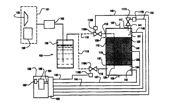
Figs. 1. With reference thereto, the apparatus 100
includes a source 101 of gas, which source may be, for
example, an air compressor 102, an oxygen tank 103, or
any other suitable gas source. When the biological agent
has an aerobic activity, the gas preferably is an oxygen '
containing gas, such as purified oxygen or air, but it is
further contemplated that a different gas may be used in
connection with the invention in some embodiments. For
example, it may be desired periodically to flush the
vessel with an inert gas, such as nitrogen gas. In such
case, the source 101 may include a tank of compressed
nitrogen (not shown). The gas optionally but preferably
is filtered through a filter 105 and is humidified at
humidifier 106, either of which may, if desired, be
provided with a heating and/or cooling mechanism, such as
a coiled jacket containing heating and/or cooling coils
(not shown). After leaving the humidifier 106, the air
passes into a culturing vessel 108 that includes a gas-
permeable culturing bed 110 disposed within an interior
space defined by a wall 112 thereof.
The culturing bed 110 comprises a substrate that
includes a biological agent disposed thereon, the
substrate being biologically conducive for the growth of
the biological agent. The substrate preferably is
selected for compatibility with the biological agent to
be cultured, and thus, for example, when cellulase
enzymes are being cultured, the substrate may comprise
recycled paper fibers, wood chips, or other cellulose-
containing source. Other substrate suitable for use in
conjunction with the invention includes grains, such as
wheat bran, cracked corn, whole grain rice, and other
organic materials such as soluble proteins. More
generally, any substrate that provides physical and
SUBSTIT'L11'E SHEET (RULE 26)
CA 02294901 1999-12-15
WO 99/54433 PCT/US99/08552
nutritive support for the biological agent and that is
suitably porous so as to be gas permeable may be
employed. By "gas permeable" is contemplated that the
bed allows gas to flow therethrough in convective thermal
communication with at least a portion of the biological
agent in the bed and/or in convective mass transfer
communication with at least a portion of the biological
agent. The substrate may comprise an inorganic material
(such as a diatomaceous earth) in admixture with a
nutritive substrate such as urea, grain, or other
suitable nutrient. The selection of a particular
substrate for a given biological agent to be cultivated
is contemplated to be within the level of ordinary skill
in the art.
The substrate is provided in the form of a solid
phase substrate, by which is contemplated a porous or
gas-permeable substrate that preferably is wet (i.e., has
sufficient moisture to promote the growth of the
biological agent), but that is not submerged in a liquid
bath. Preferably, the substrate is initially provided in
the form of wet discrete plural packings, the substrate
packings being packed in the bed with sufficient void
volume to allow the bed to be permeable to at least
compressed gas. It is contemplated that the substrate
packings will form a friable cohesive mass after the
biological agent has been allowed to grow for a
sufficient length of time, and thus no longer may be
identifiable as discrete packings.
The vessel 108 shown in Fig. 1 is equipped with two
gas inlets 115, 116, each having a gas inlet valve 115A,
116A, controlled by a respective valve actuator 115B,
116B. The vessel also is equipped with a gas outlet 117
and a gas outlet valve 117A which is operated by a gas
11 -- -
SUBSTIT'L1TE SHEET (RULE 26)
CA 02294901 1999-12-15
WO 99/54433 PCTNS99/08552 .
outlet valve actuator 117B. The valve actuators further
may be controlled by a controller 120, as discussed in
more detail hereinbelow. The controller, valves and
accompanying valve actuators are deemed optional in
connection with the invention, and thus the vessel may be
equipped with none, one, two or all three of the
illustrated valves 115A, 116A, and 117A, or may be
equipped with further valves and valve actuators if
desired.
The gas passes into the vessel 108 via one or both
of gas inlets 115, 116. The gas inlet or inlets
preferably are charged with water vapor prior to
introducing gas to thereby avoid drying out of the
culturing bed. In the illustrated embodiment, gas
leaving the humidifier 106, passes along either or both
of paths 118, 119 through respectively valves 115A and
116A and gas inlets 115 and 116 (the paths 118, 119 being
shown in broken lines as optional alternatives). The
vessel 108 preferably includes a head space 121 proximal
a boundary 122 of the bed 110 and a bottom space 124
proximal another boundary 126 of the bed 110. For
example, the bed 110 may rest on a screen 127 within the
vessel 108, the screen 127 permitting fluid flow
therethrough but not permitting solid contents of the bed
110 to pass into the bottom space 124. Entering gas may
pass either into the head space 121 via gas inlet 115, or
the bottom space 124 via gas inlet 116 (or via optional
path 128 via gas inlet 115, path 128 being shown in
broken lines as an optional alternative).
In operation, gas is introduced to the vessel in a
manner such that gas flows through at least a portion of
the bed 110. It is contemplated in preferred embodiments
of the invention that the gas will flew through the
12
sussTrrLrrE s~ET (Rtri.E 26)
CA 02294901 1999-12-15
WO 99/54433 PC'T/US99/08552
entirety of the bed to thereby maximize the benefits
attainable in accordance with the invention. It is
contemplated that the gas may not be able to flow through
the entirety of the bed, however, such as when the bed
contains occlusions or when the gas inlet and outlet are
positioned to cause gas flow only through a portion of
the bed. As shown in Fig. 3; the bed 110 comprises
discrete plural particles 130 of substrate with a
biological agent disposed thereon. Gas flows through a
first boundary 131 of the bed, as represented by arrow
132, through at least a portion 133 of the bed, as
represented by arrow 134, and through a second boundary
135 of the bed, as represented by arrow 136. The first
and second boundaries 131 and 135 are preferably but not
necessarily coextensive with the boundaries 122, 126
between the bed 110 and the head space 121 and bottom
space 124 respectively (as shown in Fig. 1). For
example, gas may be introduced into the bottom space 124
of the vessel 108 through gas inlet 116 under a pressure
greater than ambient pressure. The gas will flow from
the bottom space 124 through the bed 110 into the head
space 121 and out the gas outlet 117. In another
embodiment, the vessel is pressurized by introducing gas
at the head space through gas inlet 115 with the gas
outlet valve 117A being closed. Gas will flow into the
bed 110, even if the vessel is not equipped with a bottom
space. The gas outlet valve 117A then may be opened to
allow gas to escape from the vessel 108.
The biological agent is disposed on the bed, i.e.,
on a surface of the bed or within the bed. Preferably,
the biological agent is homogeneously dispersed
throughout the bed. While it is not intended to limit
the invention to a particular theory of operation, it is
13 - _ - --_
SUBSTITUTE SHEET (RULE 26)
CA 02294901 1999-12-15
WO 99/54433 PCT/US99/08552
believed that the passage of gas through the culturing
bed will enhance mass and/or heat transfer within the bed
as a result of connective transfer of oxygen through the
bed. For example, in the case of aerobic growth of a
biological agent, the biological agent disposed within or
growing into interior portions of the bed will be allowed
to breathe more readily than if gas were not allowed to
flow through the bed as a result of connective transfer
of oxygen through the bed. It is further believed that
volatile metabolites will be allowed to escape from the
bed via connective mass transfer.
The passage of gas through the bed may also affect
heat transfer and temperature within the bed. For
example, in the case of an oxygen-containing gas,
increasing the flow of oxygen to the bed may cause the
temperature within the bed to increase or decrease. It
is believed that the increase in oxygen flow rate will
cause the metabolic activity of microorganisms with in
the bed to increase (thus tending to increase the
temperature within the bed) but also increasing the
convection of heat away from the bed (thus tending to
decrease the temperature within the bed, so long as the
gas is at a temperature lower than that of the bed). The
rate at which the bed temperature is caused to increase
as a result of microorganism activity may be more than,
less than, or equal to, the rate at which the temperature
is caused to decrease as a result of convection of heat
away from the bed. Thus, depending on the stage of
fermentation, the flow rate of the gas, and other
factors, the temperature within the bed may be caused to
increase or to decrease by increasing the oxygen flow
rate. The effect of the flow rate preferably is
empirically determined for a given apparatus and process.
14
SUBSTITUTE SHEET (RULE 26)
CA 02294901 1999-12-15
WO 99154433 PCTNS99108552
In the case of anaerobic agents within the bed, it is
contemplated that an increase in flow rate will not cause
an increase in the metabolic activity within the bed. In
such case, increasing the flow rate of gas will be
expected to cause the bed temperature to decrease if the
gas is at a lower temperature than the bed, and to
increase if the gas is at a higher temperature.
If desired, heat may be removed from the bed by
flowing an inert gas (such as nitrogen) through the bed.
Alternatively, non-humidified gas, or gas that has a low
humidity, may be introduced to thereby cause evaporation
of water vapor from the bed and to thereby remove latent
heat from the bed. For example, the gas inlet may not be
charged with water vapor prior to introducing gas into
the bed, thus causing evaporative cooling of the bed.
Alternatively, the gas may be cooled prior to entering
the bed, or the vessel may be equipped with cooling coils
(not shown).
In a particularly preferred embodiment, the
apparatus is operated in a "pressure pulsing" mode. By
"pressure pulsing" in one embodiment is contemplated
cyclically pressurizing and depressurizing the vessel.
An example of the pressure profile within the vessel
generated in accordance with such a pressure pulsing is
shown in Fig. 2 (pressure being given as gauge pressure).
"Pressure pulsing" also encompasses cyclical increasing
and subsequently decreasing the cyclical flow rate of gas
through the bed. In either case, by "cyclical" is
contemplated repeating the pressurization/depressuriza-
tion or increase in flow rate/decrease in flow rate
operations at least once, and more preferably, at least
five times, after the initial pair of operations is
completed. In general, the pair of operations may be
- _,
SUBSTITUTE SHEET (R.ULE 26)
CA 02294901 1999-12-15
WO 99/54433 PCT/US99/08552
repeated as many times as desirable for a given
application.
It will be apparent to those skilled in the art that
the pressure pulsing may be accomplished using various
embodiments of the apparatus shown in Fig. 1, as well as
in any other suitable manner. For example, the vessel
may be equipped with a gas inlet 115 with no gas inlet
valve, and a gas outlet with gas outlet valve 117A.
Pressure pulsing then may be accomplished by closing the
gas outlet valve 117A, allowing the pressure within the
vessel to build and preferably to hold when the pressure
within the vessel reaches that pressure of the gas
incoming through the gas inlet 115, subsequently opening
the gas outlet valve to thereby allow the pressure within
the vessel to decrease to ambient pressure, and repeating
this operation. Alternatively, gas may enter the vessel
through gas inlet 116, which may or may not be equipped
with a gas inlet valve, or may come in through gas inlet
115 via optional path 128. In another embodiment of the
invention, gas enters the vessel through both gas inlets
115 and 116, at least gas inlet 116 of which is equipped
with a gas inlet valve 116A. Pressure pulsation may be
accomplished by periodically opening and closing gas
inlet valve 116A to allow respectively greater and
smaller amounts of gas to enter the vessel 108.
The gas inlet and outlet valves 115A, 116A and 117A
may be manually operated. In a preferred embodiment of
the invention, each valve is equipped with a valve
actuator 115B, 116B, and 117B respectively, each of which
modifies the state of its respective valve (for example,
by fully opening or fully closing each valve or by
incrementally increasing or decreasing the amount of
fluid that may flow through said valve). The valves and
__ _- 16
SUBSTITUTE SHEET (RULE 26)
CA 02294901 1999-12-15
WO 99/54433 PCT/US99/08552
valve actuators may be integral with the vessel or may be
remote from the vessel. For example, the valve may be
associated with the gas source (such as the valve on a
pressure vessel), or may be associated with the
compressor. The valve actuator may be, for example, a
switch for actuating the compressor (the compressor thus
serving as a valve). Alternatively, the valve actuator
may be, for example, a solenoid actuator, the gas valve
thus comprising a solenoid valve. Alternatively, the
valve and actuator may be any other suitable devices.
The valve actuators may be controlled by a controller
120.
In a highly preferred embodiment of the invention,
the apparatus is equipped with a temperature sensor 140
measuring the temperature of the bed, and/or one or more
pressure sensors 141, 142, measuring a pressure within
the vessel 108 (it being contemplated that the pressure
reported in the head space by pressure sensor 141 may
differ from that reported in the bottom space by pressure
sensor 142). In accordance with this embodiment of the
invention, the controller 120 communicates with the
temperature sensor 140 via line 144, and communicates
with the one or more pressure sensors via lines 145, 147.
The controller further communicates with valve actuators
1158, 1168, 1178 via lines 148, 149, and 150
respectively.
The controller may be any electronically or
otherwise operated mechanism. In some cases, the
controller may comprise simple control logic circuitry,
such as a wired circuit, or may comprise a timer. In one
embodiment, the controller comprises a microprocessor or
microcontroller 152 including a timer 153, a data bus
154, and an I/O interface 155 via which the sensors and
17
SUBSTITiII'E SHEET (RULE 26)
CA 02294901 1999-12-15
WO 99154433 ~ PCT/US99/08552
valve actuators communicate with the microprocessor or
microcontroller 152. The sensors provide signals to the
controller to thereby communicate temperature or pressure
data to the microprocessor or microcontroller 152, and
the microprocessor sends control signals to the valve
actuators 115B, 116B, and 117B for modifying the state of
the gas inlet and/or outlet valves.
The microprocessor or microcontroller or the logic
circuitry may be programmed via any suitable manner for
accomplishing pressure pulsation. For example, if the
pressure pulsation is accomplished with a microcontroller
or microprocessor, via~opening and closing the gas outlet
valve, one suitable control program is diagrammatically
illustrated in Fig. 4. At step 160, a delay register in
the microprocessor or microcontroller is reset with a
closed reference time, i.e., the length of time that the
gas output valve should remain closed. After the timer
has indicated the passage of this amount of time, the
microprocessor or microcontroller, at step 161, sends an
open valve signal to the gas outlet valve actuator. At
step 162, the delay register is reset with an open
reference time, i.e., a value indicating the amount of
time that the gas outlet valve should remain open.
Subsequently, after such time has passed, a close valve
signal is sent to the gas outlet valve actuator at step
163, and this cycle is repeated. The open reference time
and closed reference times preferably are empirically
determined for the given apparatus and method, and may
take into account the amount of time required for the
valve actuator to accomplish respectively opening and
closing of the valve. It is further contemplated that an
operator may terminate the control loop at any time
desired. If pressure pulsation is to be accomplished via
. - 18
SUBSTITUTE SHEET (RULE 26)
CA 02294901 1999-12-15
WO 99/54433 PCTNS99/08552
cyclical opening and closing of a gas inlet valve, the
program diagrammatically shown in Fig. 5 is one
appropriate program for the microprocessor or
microcontroller, steps 164-167 corresponding
substantially to steps 160-163 shown in Fig. 4. It
should be understood that the control programs shown in
Figs. 4 and 5 and in the subsequent figures, while
illustrated as control programs for a microcontroller or
microprocessor, may be implemented by logic circuitry or
by other suitable control mechanisms.
Upon growth of the biological agent, the temperature
within the bed may increase as the rate of metabolic
activity within the bed increases. The heat may cause
premature termination of the growth of the biological
agent, for example, if the temperature reaches an
undesirably high level. On the other hand, if the
temperature decreases below the desired operating range
of the enzyme, the metabolic activity within the bed
undesirably may decrease. When the bed includes a
temperature sensor, the microprocessor or microcontroller
may be programmed in accordance with the control logic
shown diagrammatically in Fig. 6 with respect to the
control of a gas outlet valve. At step 170 a reference
temperature, or desired maximum operating temperature of
the vessel is obtained, for example, by receiving user
input or a stored memory variable. At step 171, the
microprocessor or microcontroller receives a signal from
the temperature sensor, and at step 172, this temperature
received is evaluated as against the reference
temperature. If the received temperature is not yet as
great as the reference temperature, after a delay 173
control passes to step 171. If, on the other hand, the
temperature within the bed has reached or exceeded the
19
SUBSTIT'LTI'E SHEET (RULE 26)
CA 02294901 1999-12-15
WO 99/54433 PCT/US99/08552
reference temperature, a signal is sent to the gas outlet
valve actuator at step 174 to thereby cause the gas
outlet valve to open and to thereby cause
depressurization of the vessels. After a delay 175
another signal is sent to the gas valve actuator at step
176 to thereby cause the gas valve to close. Control
passes to step 171 after another delay 177. It is
contemplated that the delays at steps 173, 175, and 177
and the reference temperature may be empirically
determined for a given apparatus and biological agent.
The reference temperature preferably defines or is below
the maximum temperature within the desired activity range
of the biological agent.
In an alternative embodiment, as shown in Fig. 7,
the microprocessor or microcontroller may be used to
control a gas inlet valve actuator. The program is
comparable to that shown in Fig. 6 except that a close
valve signal is sent at step 178 and an open valve signal
is sent at step 179.
A further alternative program is shown in Fig. 8.
In this embodiment, a gas outlet valve is caused to open
when the temperature within the bed has reached a first
reference temperature, and the gas outlet valve is caused
to close when the temperature within the bed has fallen
to a second reference temperature. The first and second
reference temperatures are obtained as step 180, such as
by receiving input from a user or by retrieving data
valves from memory storage. Steps 181-185 are comparable
to steps 171-175 respectively of the embodiment shown in
Fig. 6. After the valve has been opened and after the
delay 185, a signal is again received from the
temperature sensor at step 186. At step 187, this _
temperature is compared to;the second reference
SUBSTTI'L1TE SHEET (RULE 26)
CA 02294901 1999-12-15
WO 99154433 PCTNS99I0855Z
temperature to determine whether the temperature within
the bed has fallen to or below the second reference
temperature. If not, after a delay 188 control passes to
step 186. If, on the other hand, the temperature has
fallen to or below the second reference temperature,
control passes to step 189, where a close valve signal is
sent to the gas outlet valve actuator. After a delay
190, control passes to step 180. The first and second
reference temperatures preferably define or are within
the range of the upper and lower temperatures of the
desired activity range of the biological agent. The bed
temperature should remain between about,30° C and 42° C
for both Trichoderma and A-niger. Fig. 9 illustrates a
similar embodiment wherein the microprocessor or
microcontroller is used to control a gas inlet valve
actuator. In this embodiment, a close valve signal is
sent at step 191 and an open valve signal is sent at step
192.
As an alternative to measuring the temperature
within the bed and opening or closing valves in response
thereto, the valve may include one or more pressure
sensors 141, 142. Most preferably, the vessel includes
one pressure sensor, which preferably is located in the
head space when the gas inlet is in the bottom space of
the vessel and is preferably located in the bottom space
of the vessel when the gas inlet is in the head space of
the vessel. Figs. 10-13 are comparable to Figs. 6-9,
respectively and diagramatically illustrate the
programming of the microprocessor or microcontroller
whereby the gas inlet or outlet valve may be opened or
closed in response to pressure changes within the vessel.
Steps 170'-192' are comparable to steps 170-192 in Figs
6-9. Fig. 10 illustrates operation of a gas outlet
_ _ - - 21
SUBSTITUTE SHEET (RULE 26)
CA 02294901 1999-12-15
WO 99/54433 PCT/US99/08552
valve, in which an open valve signal is given (at step
174') when the pressure has reached at least a reference
pressure,, and a close valve signal is subsequently given
(at step 177') after a delay 176'. Fig. 11 is comparable
to Fig. 10 and shows the control of a gas inlet valve, '
wherein an open valve signal is given at step 178' and a
close valve signal at step 179'.
Fig. 12 illustrates operation of a gas outlet valve
wherein an open valve signal is given (at step 184') when
the pressure has reached at least a first reference
pressure and a close valve signal (at step 189') when the
pressure has fallen to or below a second reference
pressure. Fig. 13 is comparable to Fig. 12 in the
operation of a gas inlet valve, wherein a close valve
signal is given at step 191' and an open valve signal at
step 192'. The pressures and delays in the foregoing
programs may be empirically determined for a given
apparatus or biological agent.
The foregoing description of programs that may be
used in conjunction with pressure pulsing is by no means
meant to be exhaustive, and it is contemplated that those
skilled in the art may find many other ways to program, a
microprocessor or microcontroller or to operate an
apparatus in accordance with the invention. For example,
instead of closing or opening a valve completely, it is
contemplated that a suitable program might cause the
valve actuator to incrementally open or incrementally
close a valve, as may be appropriate. It is further
contemplated that other microprocessor or microcontroller
programs or other logical circuitry or control scheme may
be developed by those skilled in the art.
After growth of the biological agent, at least a _
portion of-the biological agent is recovered from the
__ _ 2 2
SUBST1TL1TE SHEET (RULE 26)
CA 02294901 1999-12-15
WO 99/54433 PCT/US99/08552
vessel. By "recovering" the biological agent is
contemplated any action by which any portion of the
biological agent, or the biological product produced by
the biological agent, is removed from the vessel, whether
such biological agent or product was present initially in
the vessel or was grown in the vessel. For example, as
shown in Fig. 1, the vessel 108 may be provided with a
liquid intake port 107 and a drain 109. To recover the
biological agent, sterilized water may be fed into the
vessel via intake port 107, and the biological agent may
be recovered via removal of the liquid through the drain
109. The biological agent then may be continue to be
cultivated. Water or nutrients may be added as may be
appropriate.
The following non-limiting Examples are provided for
illustration of the present invention.
EXAMPLE 1
A two liter New Brunswick glass jar fermentor was
equipped with a metal mesh screen to hold a wet porous
solid bed having a depth of about 10 centimeters. The
fermentor was equipped with a gas inlet for introducing
air to the bottom space of the fermentor (beneath the
screen), a gas outlet valve leading from the head space
(above the bed), a gas outlet solenoid valve (Omega
Technologies Co.) and an electrical timer (ChronTrol)
serving as a controller. Air was allowed to flow into
the bottom space and then upwards through the porous bed
into the head space. Pressure pulsation was created by
periqdically opening and closing the gas outlet valve.
The bed included a substrate with an Aspergillus niger
culture disposed thereon.
- _ . - - 2 3
SUBSTITUTE SHEET (RULE Z6)
CA 02294901 1999-12-15
WO 99154433 PCT/US99/08552
With pressure pulsation, the bacteria growth was
uniform and heavy throughout the bed. The porous bed
turned totally black because of the heavy formation of
the black colored spores by the A. niger culture. The
whole bed was "loose" and, in fact, it was difficult to
take the whole bed out of the jar without having portions
of the bed falling off.
Example 1 was repeated without pressure pulsation.
Only the bottom portion of the porous bed near the air
inlet became blackened, and the central portion of the
bed became tightly packed, with little mycelial growth
and even less spore formation.
EXAMPLE 2
In a set-up identical to that in EXAMPLE l, sterile
water was pumped into the jar from the bottom up to
extract enzyme from the Porous Bed. After the liquid
extract was pumped out, there were still some liquid
which slowly drained from the bed into the bottom space.
Once the drainage was complete, air flow was re-
introduced to start the bioprocess again. Once good
growth was observed again, the extraction was repeated.
The first extraction was done three days after the
innoculation. The second extraction was done 24 hours
later, and the extraction was then repeated daily for
five days. The whole residual mass was then taken out of
the jar and thoroughly extracted with added detergent.
This method of enzyme production was done with the
A. niger culture for cellobiase and also with the
Trichoderma culture for the whole cellulase complex. The
results were as follows:
24
SUBSTITUTE SHEET (RULE 26)
CA 02294901 1999-12-15
WO 99/54433 PCT/US99/08552
Cel ulases y Ce.~obiase by
Trichoderma A. niger
Washing Day FPU Extracted Washing/Day IU
Extracted
18C/3rd 14149.8 1st/3rd 17049.6
2"d/4th 12 92 9 . 7 2nd/4th 172 90 .
3re/5th 9$55.2 3rd/5th 17406.9
4tn/6tn 6645.8 4th/6tn 15222.2
Final/8th 9802. Final/7th 37294.2
Wash with 16560.
Surfactant 831.
Drainage
Total 70773.5 104,263
From these results and the measured amounts of the solid
enzyme products, the enzyme productivity was calculated
to be 806 FPU/hour-liter for cellulase complex from
Trichoderma. In the case of cellobiase-producing A.
niger, a productivity of 620 International Units/hour-
liter was achieved. One international "filter paper
unit" (FPU) is defined to be the amount of cellulases
that can produce one micro-mole of glucose per minute
from cellulose.
- -2 5
SUBSTITUTE SHEET (RULE 26)
CA 02294901 1999-12-15
WO 99/54433 PCTNS99/08552
COMPARATIVE EXAMPLE 1
. A Trichoderma culture was cultivated on recycled
paper fibers in a solid phase fermentation in a L000 ml
fermentor (a laboratory Erlenmeyer flask) to produce high
potency cellulases. The fermentation was accomplished by
placing the flask at room temperature on a laboratory -
bench top. After the fermentation was completed, the
whole wet solids were air dried to become the final
3.0 enzyme product. This product contains 246 FPU/gram, from
which the productivity of the fermentor can be calculated
to be 234 FPU/hour-liter of fermentor volume. The
productivity of the solid phase fermentation was found to
be higher than those of submerged fermentation of
different Trichoderma cultures, reported in the
literature and collected in the following Table:
Prior Art Cellulase Productivity
in Liquid Phase Fermentation
Culture Substrate Productivity in
FPU/hour-liter
RUT-30 5% Solkfloc 87
RUT 30 10% steam exploded 83
aspen
RUT 30 2.2% steam exploded 37
poplar
RL-P37 6% lactose 158
SVG-17 3.7% pretreated grain 60
husk
It is thus seen that the productivity of the method
used in Example 2 for fermentation of the Trichoderma
culture is more than 500% better than the productivity of
liquid submerged fermentation reported in the prior art,
and 344% higher than that of Comparative Example 1.
2s
SUBSTTI'L1TE SHEET (RULE 26)
CA 02294901 1999-12-15
WO 99/54433 PCT/US99/08552
EXAMPLE 3
and
COMPARATIVE EXAMPLES 2-5
A mixture including 200 g corn fiber (14% moisture
content, from A.E. Staley, Decatur, IL), 60 g ground
corn, 30 ml corn steeping liquid (A.E. Staley), 4.0 g
(NH4 ) 2504 , 2 . 0 g K42P04 , and 600 ml water was prepared
(final moisture content was about 75%). This mixture was
autoclaved for 30 minutes at 121° C and allowed to cool
to form a substrate. To this substrate was added 20 g
solid A. Niger culture in a septic hood.
EXAMPLE 3
Most (80%) of the substrate/biological agent mixture
was transferred to a 2 L fermentor with a 15 cm packing
bed height equipped with a gas inlet, a gas outlet, and a
gas outlet solenoid valve. The fermentator was operated
with the pressure pulse profile shown in Fig. 2. An air
inlet was provided for the bottom space, and air was
allowed to flow continuously into the bed. The gas
outlet led from the head space in the vessel, and the gas
outlet valve was controlled by a timer.
Fermentation was allowed to proceed for 60 hours,
after which the substrate became black. Subsequently,
100 ml water containing 0.2% (NH4)S04 was introduced to
wash out enzymes. This washing out was repeated once
each day for three days. Samples of the extract were
analyzed each day for enzyme activity. Before activity
analysis, 10 g was solid sample were mixed with 10 ml
0.05N pH 4.5 citrate buffer in a 250 ml flask. The
mixture was shaken for three hours in a 25° shaker,
filtered to remove solids and spores, and stored in a
refrigerator.
- _ . - ' 27
SUBSTITUTE SHEET (RULE 26)
CA 02294901 1999-12-15
WO 99/54433 PC'f/US99/08552
COMPARATIVE EXAMPLES 2-5
The substrate mixture prepared as discussed above
was divided and transferred.to four 250 ml Erlenmeyer
flasks as follows:
Comparative Example 2 30 g
Comparative Example 3 60 g
Comparative Example 4 40 g (with 100 ml water)
Comparative Example 5 40 g (with 100 ml 5%
glucose solution).
The mixture of Comparative Examples 2, 4, and 5 were set
in a 30° C shaker at 200 rpm to begin fermentation. The
mixture of Comparative Example 3 was allowed to ferment
at ambient temperature without shaking.
The following results were obtained:
Physical Phenomena
Day Example Comparative Comparative
3 Example Example 3
2
Color Temp. Color Temp. Color Temp.
0 Brown 25C Brown 25C Brown 25C
1 Light 35C Brown 30C Brown 25C
White
2 Grey 33C Brown 30C Brown 25C
3 Black 33C Light 30C Brown 25C
White
4 Black 32C Light 30C Light 25C
White White
5 Black 30C White 30C White 25C
6 Black 28C White 30C White 25C
7 Black 28C Grey 30C White 25C
_ ._ - 28
S~1BSTTTUTE SHEET (RULE 26)
CA 02294901 1999-12-15
WO 99/54433 PC'T/US99/08552
Enzyme Activity (glucoamylase)
Example ComparativeComparativeComparativeComparative
3 Example Example Example Example
2 3 4 5
IU/g 522.5 213.3 157.4 97.29 153.25
IU/ml - - - 8.27 13.02
IU/mg 2.12 1.52 1.12 0.86 1.15
Protein
It is thus seen that the enzyme activity per mg
protein realized in accordance with Example 3 was
superior as compared with that realized in accordance
with the Comparative Examples. The following further
results were obtained in connection with Example 3:
Production of Glucoamylase
During Solid State fermentation
Sample Volume IU/ml Total IU IU/g, o Hour
(ml) dry
1St 1000 12.2 12290 63.03 12.06 60
9
Wash
2nd 1050 10.23 10741.5 55.08 10.54 84
~
Wash
3rd 1060 13.03 13811.8 70.83 13.56 108
Wash
Final 14885.5 4.37 65049.6 333.59 63.84 132
solid
Total - - 101892.9 522.5 100 132
Final solid dry weight: 195 grams
Moisture content of final solid culture: 86.9%
Volume: 14885.5 ml
_ - . - - 29
SUBSTITUTE SHEET (RULE 26)
CA 02294901 1999-12-15
WO 99154433 PCTNS99/08552
Production of Cellobiase During
Solid State Fermentation
Sample Volume IU/ml Total IU/g, % Hour
(ml) IU dry
1st 1000 14.07 14070 72.15 11.61 60
Wash
2nd 1050 . 16.4 17220 88.31 14.21 84
Wash
3ra 1060 13.2 13992 71.75 11.54 108
Wash
Final 14885.5* 5.1 75916 389.31 62.64 132
Solid
Total - - 121198 621.52 100 ~ 132
Final solid dry weight: 195 grams
Moisture Content of final solid culture: (10-1.31)/10*
100%=86.9%
*Volume = (195/13.1%/10)* 100 ml = 14885.5 ml
Thus, it is seen that the foregoing general objects
have been satisfied. A method for cultivating a
biological agent has been provided, and also an apparatus
useful in accomplishing same.
SUBSTTITTfE SHEET (RULE 26)