Note: Descriptions are shown in the official language in which they were submitted.
CA 02294902 1999-12-29
WO 99/03415 PCT/US98/14424
MULTI-AXIAL BONE SCREW
Background of the Invention
The present invention concerns a bone fixation assembly, particularly
useful for engagement in the vertebrae. In particular, the invention provides
a bone
screw assembly that is capable of a continuous range of three-dimensional
angular
orientations with respect to an elongated member extending along the spine.
Several techniques and systems have been developed for correcting and
stabilizing the spine and for facilitating fusion at various levels of the
spine. In one
type of system, a bendable rod is disposed longitudinally along the length of
the
spine or vertebral colunui. The rod is preferably bent to correspond to the
normal
curvature of the spine in the particular region being instrumented. For
example,
the rod can be bent to form a normal kyphotic curvature for the thoracic
region of
the spine, or a lordotic curvature for the lumbar region. In accordance with
such a
system, the rod is engaged to various vertebrae along the length of the spinal
column by way of a number of fixation elements. A variety of fixation elements
can be provided which are configured to engage specific portions of the
vertebra.
For instance, one such fixation element is a hook that is configured to engage
the
laminae of the vertebra. Another prevalent fixation element is a spinal screw
which can be threaded into various aspects of the vertebral bone.
In one typical procedure utilizing a bendable rod, the rod is situated on
opposite sides of the spine or spinous processes. A plurality of bone screws
are
threaded into a portion of several vertebral bodies, very frequently into the
pedicles
of these vertebrae. The rods are affixed to these plurality of bone screws to
apply
corrective and stabilizing forces to the spine.
One example of a rod-type spinal fixation system is the TSRHO Spinal
System sold by Danek Medical, Inc. The TSRHO System includes elongated rods
and a variety of hooks, screws and bolts all configured to create a segmental
construct throughout the spine. In one aspect of the TSRHO System, the spinal
CA 02294902 1999-12-29
WO 99/03415 PCT/US98/14424
2
rod is connected to the various vertebral fixation elements by way of an
eyebolt.
In this configuration, the fixation elements are engaged to the spinal rod
laterally
adjacent to the rod. In another aspect of the TSRHO System, a variable angle
screw is engaged to the spinal rod by way of an eyebolt. The variable angle
screw
allows pivoting of the bone screw in a single plane that is parallel to the
plane of
the spinal rod. Details of this variable angle screw can be found in U. S.
Patent
No. 5,261,909 to Sutterlin et al., owned by the Assignee of the present
invention.
One goal achieved by the TSRHO System is that the surgeon can apply vertebral
fixation elements, such as a spinal hook or a bone screw, to the spine in
appropriate
anatomic positions. The TSRHO System also allowed the surgeon to easily
engage a bent spinal rod to each of the fixation elements for final
tightening.
Another rod-type fixation system is the Cotrel-Dubosset/CD Spinal System
sold by Sofamor Danek Group, Inc. Like the TSRHO System, the CDO System
provides a variety of fixation elements for engagement between an elongated
rod
and the spine. In one aspect of the CDO System, the fixation elements
themselves
include a body that defines a slot within which the spinal rod is received.
The slot
includes a threaded bore into which a threaded plug is engaged to clamp the
rod
within the body of the fixation element. The CDO System includes hooks and
bone screw with this "open-back" configuration. Details of this technology can
be
found in U. S. Patent No. 5,005,562 to Dr. Cotrel. One benefit of this feature
of
the CDO System is that the fixation element is positioned directly beneath the
elongated rod. This helps reduce the overall bulkiness of the implant
construct and
minimizes the trauma to surrounding tissue.
On the other hand, these fixation elements of the CDO System are capable
only of pivoting about the spinal rod to achieve variable angular positions
relative
to the rod. While this limited range of relative angular positioning is
acceptable for
many spinal pathologies, many other cases require more creative orientation of
a
bone screw, for instance, relative to a spinal rod. Certain aspects of this
problem
are addressed by the variable angle screw of the TSRHO System, as discussed in
the '909 Patent. However, there is a need for a bone screw that is capable of
angular orientation in multiple planes relative to the spinal rod. Preferably,
the
CA 02294902 1999-12-29
WO 99/03415 PCTIUS98/14424
3
bone screw is capable of various three-dimensional orientations with respect
to the
spinal rod. Screws of this type have been referred to as multi-axial or multi-
axial
bone screws.
Others have approached the solution to this problem with various multi-
axial screw designs. For example, in U. S. Patent No. 5,466,237 to Byrd et
al., a
bone screw is described which includes a spherical projection on the top of
the
bone screw. An externaily threaded receiver member supports the bone screw and
a spinal rod on top of the spherical projection. An outer nut is tightened
onto the
receiver member to press the spinal rod against the spherical projection to
accommodate various angular orientations of the bone screw relative to the
rod.
Vdhile this particular approach utilizes a minimum of components, the security
of
the fixation of the bone screw to the rod is lacking. In other words, the
engagement or fixation between the small spherical projection on the bone
screw
and the spinal rod is readily disrupted when the instrumentation is subjected
to the
high loads of the spine, particularly in the lumbar region.
In another approach shown in U. S. Patent No. 4,946,458 to Harms et al., a
spherical headed bone screw is supported within separate halves of a receiver
member. The bottom of the halves are held together by a retaining ring. The
top
of the receiver halves are compressed about the bone screw by nuts threaded
onto a
threaded spinal rod. In another approach taken by Harms et al., in U. S.
Patent No.
5,207,678, a receiver member is flexibly connected about a partially spherical
head
of a bone screw. Conical nuts on opposite sides of the receiver member are
threaded onto a threaded rod passing through the receiver. As the conical nuts
are
threaded toward each other, the receiver member flexibly compresses around the
head of the bone screw to clamp the bone screw in its variable angular
position.
One detriment of the systems in the two Harms et al.. patents is that the
spinal rod
must be threaded in order to accept the compression nuts. It is known that
threaded rods can tend to weaken the rods in the face of severe spinal loads.
Moreover, the design of the bone screws in the '458 and '678 Patents require a
multiplicity of parts and are fairly complicated to achieve complete fixation
of the
bone screw.
CA 02294902 1999-12-29
WO 99/03415 PCT/US98/14424
4
A third approach is shown in U. S. Patent No. 5,304,179 to Wagner, which
shows a bone screw fixed inside a bushing and angled with respect to the
longitudinal axis of the bushing. The bushing is rotatable within a portion of
a
connector angled with respect to the axis of the adjoining instrumentation.
The
connector is rotatable around the instrumentation axis. One detriment of the
Wagner system is that only discrete positions of a bone screw in three-
dimensional
space can be achieved. Further, the Wagner system also requires threaded
spinal
rods and a multiplicity of complicated parts with their above-described
drawbacks.
There is therefore a need remaining in the art for a multi-axial bone
engaging fastener that can be readily and securely engaged to an elongated
member, such as a spinal rod, of any configuration - i.e., smooth, roughened,
knurled or threaded. There is also a need for such a multi-axial bone engaging
fastener which minimizes the profile and bulk of the components used to engage
the bone fastener, such as a bone screw, to the spinal rod in its various
angular
orientations. Further, there is a need for a multi-axial engaging fastener
which
allows the positioning of the fastener at a continuous range of spatial angles
between the fastener and an axis perpendicular to the elongated member.
CA 02294902 1999-12-29
WO 99/03415 PCTIUS98/14424
SUMMARY OF THE INVENTION
In one embodiment of the invention, a spinal fixation assembly is provided
that includes a bone engaging fastener, such as a bone screw, and an elongated
5 member, such as a spinal rod. The fixation assembly includes a multi-axial
assembly that permits fixation of the bone screw to the spinal rod at any of a
plurality of angles relative to the rod in three-dimensional space. In one
aspect of
the invention, a bone screw is included having a head with a tool-engaging
recess
defined therein and a shank portion. In one embodiment, the bone screw
includes
a circumferential bead between the head and the shank portion of the bone
screw.
In another embodiment, the bone screw includes a tapered shank portion below
the
head.
The multi-axial assembly also includes a receiver member having a bore
therethrough from a top end to a bottom end. The walls defining the bore are
tapered near the bottom or distal end of the receiver member. The receiver
member also includes a channel convnunicating with the bore and having an
upper
opening at the top of the receiver member for insertion of the elongated
member.
In a further aspect of the invention, the multi-axial assembly includes an
outer wedge member having a tapered outside surface and which is insertable
into
the bore of the receiver member to self-lock with the tapered wall of the
bore. The
outer wedge member includes a bore therethrough which is inclined with respect
to
the central axis of the outer wedge member. In one aspect, the inclined bore
can be
inwardly tapered from the top to the middle of the outer wedge member, and
then
sloped outward to an opening at the bottom of the outer wedge member.
The multi-axial assembly additionally includes an inner wedge member
having a tapered outside surface and which is insertable into the inclined
bore of
the outer wedge member to self-lock with the tapered wall of the inclined
bore.
The inner wedge member also includes a bore therethrough which is inclined
with
respect to the central axis of the inner wedge member. In one embodiment, the
bore in the inner wedge member is cylindrical and a groove is included in the
wall
defining the bore for mating with a circumferential bead of the bone screw. In
CA 02294902 2006-01-30
61211-1463
6
another embodiment, the bore in the inner wedge member is
tapered to self-lock with a tapered shank portion of the
bone screw.
The present invention provides an assembly that
enables a bone engaging fastener to be fixed to an elongated
member at a continuous range of angular orientations
relative to the elongated member. In one aspect of the
invention, the bone engaging fastener, wedge members, and
elongated member are "top loaded" by insertion into the top
or proximal opening in the receiver member. When the
desired orientation of the fastener is achieved, the
fastener can be fixed through self-locking of the bone
fastener within the inner wedge member, of the inner wedge
member within the outer wedge member, and of the outer wedge
member within the receiver member. Self-locking can occur
as the fastener is engaged in a bone, as for example when a
bone screw is threaded into a bone and tightened.
Alternatively, self-locking can occur as the assembly is
attached to an elongated member, as for example when a
spinal rod presses down on the fastener.
The preferred embodiment of the multi-axial bone
fixation assembly provides the advantage of a solid fixation
between a spinal rod and a bone engaging fastener regardless
of the three-dimensional angle between the two components.
A further benefit of the present invention is the minimum
number of components necessary to achieve this solid
fixation. Another benefit resides in the self-locking
capabilities of the wedge members and the receiver member.
Other benefits and certain objects of the invention will
become apparent upon consideration of the following written
description and accompanying figures illustrating one
embodiment of the invention.
CA 02294902 2006-01-30
61211-1463
6a
More particularly, according to the present
invention, there is provided a bone fixation assembly for
engaging an elongated member comprising: a receiver member
defining a channel for receiving the elongated member, said
receiver member having a bore therethrough for defining an
inner surface; a first wedge member for complementary mating
within said inner surface of said receiver member, said
first wedge member defining a first central axis, said first
wedge member further defining a bore therethrough which is
inclined with respect to said first central axis; a second
wedge member for complementary mating within said bore of
said first wedge member, said second wedge member defining a
second central axis, said second wedge member further
defining a bore therethrough which is inclined with respect
to said second central axis; and a bone engaging fastener
for complementary mating within said bore of said second
wedge member.
According to another aspect of the present
invention, there is provided a bone fixation assembly for
engagement to an elongated member comprising: a bone
engaging fastener; a receiver member defining a channel for
receiving the elongated member, said receiver member having
a bore therethrough defining an inner surface, said inner
surface having at least a portion which is inwardly tapered;
a first wedge member defining a first central axis, said
first wedge member further defining a bore therethrough,
said bore being inclined with respect to said first central
axis and tapered, and said first wedge member further having
an outer surface which is tapered for complementary mating
with said tapered portion of said inner surface of said
receiver member; and a second wedge member defining a second
central axis, said second wedge member further defining a
bore therethrough, said bore being inclined with respect to
CA 02294902 2006-01-30
61211-1463
6b
said second central axis, and said second wedge member
further having an outer surface which is tapered for
complementary fitting within said bore of said first wedge
member, wherein said inner surface of said second wedge
member includes means for holding said bone engaging
fastener.
According to a further aspect of the present
invention, there is provided a bone screw assembly
comprising: a bone screw having a head portion, a shank
portion, and a circumferential bead therebetween; a receiver
member for receiving an elongated member, said receiver
member having a bore therethrough defining an inner surface,
said inner surface having at least a part which is inwardly
tapered; a first wedge member having a first central
longitudinal axis, said first wedge member further having a
bore therethrough, said bore being inclined at an angle of
about fifteen degrees to said first central longitudinal
axis, said bore further defining tapered walls, and said
first wedge member further having a tapered outer surface
for fitting with said tapered part of said inner surface of
said receiver member; and a second wedge member having a
second central longitudinal axis, said second wedge member
further having a bore therethrough, said bore being inclined
at an angle of about fifteen degrees to said second central
longitudinal axis, said bore further defining an inner
surface, said inner surface of said second wedge member
having a groove for receiving said circumferential bead said
second wedge member further having a tapered outer surface
for fitting with said tapered walls of said bore of said
first wedge member.
CA 02294902 1999-12-29
WO 99/03415 PCT/US98/14424
7
DESCRIPTION OF THE FIGURES
FIG. 1 is a side-elevational view of a multi-axial bone fixation assembly in
accordance with one embodiment of the present invention.
FIG. 2 is a cross-sectional view of a multi-axial bone fixation assembly as
depicted in FIG. 1.
FIG. 3 is a top view of the receiver member of the bone fixation assembly
shown in FIGS. 1 and 2.
FIG. 4 is a cross-sectional view along lines 4-4 and viewed in the
direction of the arrows of the receiver member as depicted in FIG. 3.
FIG. 5 is a side elevational view of a bone screw for use in the bone
fixation assembly shown in FIGS. 1 and 2.
FIG. 6a is a top view of the outer wedge member of the bone fixation
assembly of FIGS. I and 2.
FIG. 6b is a side elevational view of the outer wedge member as depicted in
FIG. 6a.
FIG. 7 is a cross-sectional view along lines 7-7 and viewed in the
direction of the arrows of the outer wedge member as depicted in FIG. 6a.
FIG. 8a is a top view of the inner wedge member of the bone fixation
assembly shown in FIGS. I and 2.
FIG. 8b is a side elevational view of the inner wedge member as depicted in
FIG. 8a.
FIG. 9 is a cross-sectional view along the lines 9-9 and viewed in the
direction of the arrows of the inner wedge member as depicted in FIG. 8a.
FIG. 10 is a side elevational view of a multi-axial bone fixation assembly in
accordance with an additional embodiment of the present invention.
FIG. 11 is a cross-sectional view of the multi-axial bone fixation assembly
as depicted in FIG. 10.
' FIG. 12a is a side elevational view of a second embodiment of the inner
wedge member of the present invention.
CA 02294902 1999-12-29
WO 99/03415 PCTIUS98/14424
8
FIG. 12b is a cross-sectional view of the embodiment of the inner wedge
member depicted in FIG. 12a.
FIG. 13a is a side elevational view of a second embodiment of the outer
wedge member of the present invention.
FIG. 13b is a cross-sectional view of the embodiment of the outer wedge
member depicted in FIG. 13a.
FIG. 14 is a side elevational view of the bone fixation assembly of the
present invention in which the bone screw is oriented at an angle with respect
to a
central axis of the receiver member of the present invention.
CA 02294902 1999-12-29
WO 99/03415 PCT/US98/14424
9
DESCRIPTION OF THE PREFERRED EMBODIMENTS
For the purpose of promoting an understanding of the principles of the
invention, reference will now be made to preferred embodiments thereof and
specific
language will be used to describe the same. It will nevertheless be understood
that no
limitation of the scope of the invention is thereby intended, such alterations
and
further modifications in the invention, and such further applications of the
principles
of the invention as described therein being contemplated as would normally
occur to
one skilled in the art to which the invention relates.
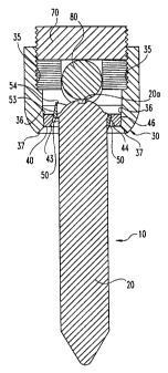
Referring generally to FIGS. 1 and 2, the components of a multi-axial bone
fixation assembly 10 in accordance with a preferred embodiment of the present
invention are shown. The multi-axial assembly 10 includes a bone screw 20
configured to engage a bone, such as a vertebra. The assembly further includes
a
receiver member 30 for supporting bone screw 20 and for linking assembly 10
with a
spinal rod 80. The assembly further includes an outer wedge member 40 for
engagement within the interior of receiver member 30, and an inner wedge
member
50 for engagement between bone screw 20 and outer wedge member 40.
In accordance with one aspect of the invention, bone screw 20 is configured
as shown in FIG. 5. Bone screw 20 includes a threaded shank portion 21, a head
portion 22, and a circumferential bead 24. Threaded shank portion 21 carries
threads
configured to anchor the bone screw solidly within a bone. Most preferably,
the
threads are cancellous threads, or threads readily adapted for solid fixation
within the
cancellous bone of the vertebral body. It is understood that threaded shank 21
can
have a variety of configurations depending on the nature of the bone within
which
bone screw 20 is engaged. Moreover, the length of threaded shank 21 can be
adjusted
depending on the anatomy or characteristics of the bone within which bone
screw 20
is driven. In one specific embodiment, threaded shank 21 has a length of about
1.5
inches, and is configured with threads for engagement within the pedicle of a
lumbar
vertebra.
Head portion 22 is located at the upper or proximal end of bone screw 20.
Head portion 22 preferably includes a tool receiving slot or recess 20a(see
FIG. 2) to
CA 02294902 1999-12-29
WO 99/03415 PCT/US98/14424
accommodate a screw driving tool. In a specific embodiment, head portion 22 is
in
the shape of a portion of a sphere, and the circumference of the bottom or
distal edge
22a of head portion 22 is preferably smaller than the circumference of the
threaded
shank portion 21. Bead 24 lies between head portion 22 and threaded shank 21.
5 Bead 24 extends circumferentially around the top or proximal end of threaded
shank
21 and engages inner wedge member 50 in a manner to be described hereinafter.
In
one specific embodiment, head 22 is a portion of a sphere of about 0.295
inches in
diameter, bead 24 has a width of about 0.040 inches and a diameter of about
0.311
inches, and threaded shank 21 has a length of about 1.534 inches and a
diameter of
10 about 0.295 inches.
Referring now to FIGS. 3 and 4, bone screw assembly 10 includes a receiver
member 30. Receiver member 30, in a preferred embodiment, is generally
cylindrical, having a bore 31 therethrough and two opposed truncated side
walls 32.
Bore 31 and receiver member 30 define a common central longitudinal axis 38.
The
side walls 32 of receiver member 30 define a channel 33 for receiving spinal
rod 80
which extends across receiving member 30, communicating generally
perpendicularly with bore 31. Channel 33 may extend to a sufficient depth
within
receiver member 30 that spinal rod 80 may contact head portion 22 of bone
screw 20
in the finished assembly 10, as further described hereafter.
The inside of receiver member 30 includes a series of surfaces. Entry surface
34 is angled toward axis 38 to facilitate placement of other parts of bone
screw
assembly 10 therein, as hereinafter further described. Upper inner surface 35
may be
substantially parallel to the outer surface of receiver member 30 and may, for
example, be internally threaded to accommodate the plug member of the CD
System noted above and shown in FIG. 3. Lower inner surface 36 is angled
toward
axis 38, thereby forming a self-locking taper for holding outer wedge member
40 as
hereinafter further described. Exit surface 37 is angled outward from axis 38
to
provide greater range of axial movement for bone screw 20 in the completed
bone
fixation assembly 10. In the preferred embodiment, channel 33 intersects both
the
upper and lower inner surfaces 35, 36. In the specific embodiment, lower inner
surface 36 includes a Morse taper, preferably forming a four degree angle with
axis
CA 02294902 1999-12-29
WO 99/03415 PCT/US98/14424
11
38 of receiver member 30, and exit surface 37 comprises a 45 degree angle with
axis
38 of receiver member 30.
Referring now to FIGS. 6a, 6b and 7, there is shown an outer wedge member
40 according to a preferred embodiment of the present invention. Outer wedge
member 40 is generally in the shape of a washer having a central axis 41, an
inclined
bore 42, and an outer surface 46. Inclined bore 42 extends through outer wedge
member 40 from top to bottom and defines a longitudinal axis 45 which is not
parallel
to central axis 41. In one specific embodiment, the angle formed by bore axis
45 and
central axis 41 is fifteen degrees. The surfaces defining bore 42 include an
upper
tapered wal143 and a lower wa1144. Upper tapered wall 43 is tapered toward
bore
axis 45, thereby forming a self-locking taper for holding lower wedge member
50 in a
manner described hereafter. In one specific embodiment, upper tapered wa1143
forms an angle of four degrees with bore axis 45. In a second and third
specific
embodiment, upper tapered wa1143 forms an angle of fifteen and thirty degrees,
respectively, with bore axis 45. Lower wa1144 is generally conical, flaring
outward
toward the bottom of outer wedge member 40 to allow greater range of axial
movement for bone screw 20 in the completed bone fixation assembly 10. Tapered
outer surface 46 is angled from top to bottom toward central axis 41 of outer
wedge
member 40. In a specific embodiment, tapered outer surface 46 includes a Morse
taper, forming an angle of four degrees with central axis 41. Tapered outer
surface 46
self locks with tapered inner surface 36 of receiver member 30 in a manner to
be
described hereafter.
Referring now to FIGS. 8a, 8b and 9, an inner wedge member 50 according to
a preferred embodiment of the present invention is shown. Inner wedge member
50
is generally in the shape of a washer having a central axis 51, an inclined
bore 52, and
an outer surface 53. Inclined bore 52 extends through inner wedge member 50
top to
bottom and defmes a longitudinal axis 56 which is not parallel to central axis
51.
Bore 52 is defined by generally cylindrical inner surface 54. In one specific
embodiment, the angle formed by bore axis 56 and central axis 51 is fifteen
degrees.
Inner surface 54 has an inner diameter slightly greater than the outer
diameter of
circumferential bead 24. Inner surface 54 also includes inner circumferential
groove
CA 02294902 1999-12-29
WO 99/03415 PCT/US98/14424
12
55. Groove 55 is shaped to mate with circumferential bead 24 of bone screw 20
and
is thereby a means for holding bone screw 20. Outer surface 53 of inner wedge
member 50 is tapered with respect to central axis 51. In one specific
embodiment, the
angle between outer surface 53 and central axis 51 is four degrees. In a
second and
third specific embodiment, outer surface 53 and central axis 51 form angles of
fifteen
and thirty degrees, respectively.
In use, outer wedge member 40 is inserted into bore 31 of receiver member 30
through the top or proximal end of receiver member 30. Tapered outer surface
46 of
outer wedge member 40 fits within tapered lower inner surface 36 of receiver
member 30. Outer wedge member 40 is rotatable within bore 31 until finally
seated
and tightened. Inner wedge member 50 is inserted into bore 42 of outer wedge
member 40. Tapered outer surface 53 of inner wedge member 50 fits within
tapered
upper wall 43 of bore 42 of outer wedge member 40. Inner wedge member 50 is
rotatable within bore 42 until finally seated and tightened. Bone screw 20 is
inserted
into bore 52 of inner wedge member 50, with circumferential bead 24 of bone
screw
fitted into groove 55. Bone screw 20 is then preferably threaded at least
partially
into the bone.
After the components are in place, the surgeon may realize any of a
continuous range of three-dimensional angular orientations of bone screw 20
with
20 respect to axis 38 (and thereby with respect to a spinal rod within channel
33) by
rotating wedge members 40 and/or 50, with respect to each other and/or with
respect
to receiver member 30. The surgeon can manipulate the receiver member 30 with
respect to the bone screw to align channel 33 with a spinal rod already in
place or to
be placed when a plurality of assemblies 10 are implanted. As noted, in one
specific
embodiment the angle between central axis 41 and bore axis 45 of outer wedge
member 40 and the angle between central axis 51 and bore axis 56 of inner
wedge
member 50 are each fifteen degrees. In that embodiment, bone screw 20 can
assume
any position which forms an angle of zero to thirty degrees between bone screw
20
and axis 38 of receiver member 30.
When the desired angle and position of bone screw 20 is achieved, a pushing
force on head 22 and/or a pulling force on shank 21 and/or receiver member 30
is
CA 02294902 1999-12-29
WO 99/03415 PCT/US98/14424
13
applied to seat and tighten bone screw 20 and inner wedge member 50 in outer
wedge
member 40 and outer wedge member 40 in receiver member 30. In one embodiment,
a pushing force is provided by a spinal rod 80 which is inserted into channel
33 to
contact head 22 of bone screw 20. A retaining means 70, such as a threaded nut
or
plug, is used to retain the spinal rod in contact with head 22. Alternatively
or
additionally, in this instance head 22 or spinal rod 80 or both may include
additional
feature(s) to enhance fixation. Though spinal rod 80 and head 22 contact
nominally
at a single point, the wedge members 40, 50 are solidly locked thereby.
A pulling force can be provided by further tightening of bone screw 20 into
the bone. In this instance, receiver member 30 will contact the bone as well
to
provide a reactive force as bone screw 20 is tightened. Further, in this
example
contact between spinal rod 80 and head 22 of bone screw 20 is unnecessary.
An alternative embodiment of the invention is shown in FIGS. 10 and 11. In
FIG. 10, bone screw 20 includes head 61 and a shank portion 62 having a self-
locking
taper. Additionally, inner surface 63 of inner wedge member 50 is tapered.
Bone
screw 20 is inserted into inner wedge member 50, and friction fit is achieved
between
tapered shank portion 62 and inner surface 63, with inner surface 63 forming a
means
for holding bone screw 20. In this alternative embodiment, bone screw 20
having
shank 62, inner wedge member 50 having inner surface 63, outer wedge member
40,
and receiver member 30 are assembled in the manner already described. Varying
spatial angles of bone screw 20 with respect to axis 38 are realized by
rotation of
bone screw 20, inner wedge member 50, and/or outer wedge member 40 within
receiver member 30 in the manner already described.
The above-disclosed components of the present invention are preferably
comprised of a biocompatible material such as stainless steel, titanium, or
other
material suitable for in vivo implantation.
While the invention has been illustrated and described in detail in the
drawings and foregoing description, the same is to be considered as
illustrative and
not restrictive in character, it being understood that oiily the preferred
embodiments
have been shown and described and that all changes and modifications that come
within the spirit of the invention are desired to be protected.