Note: Descriptions are shown in the official language in which they were submitted.
CA 02294908 1999-12-15
WO 99/04296 PCT/US98/14774
DEVICE FOR CONCENTRATING OPTICAL RADIATION
TECHNICAL FIELD
The present invention relates to optics, particularly to the field of optical
concentrators for
gathering optical radiation. The optical concentrator made by the subject of
the present invention may
be used in all technical areas where concentrated optical radiation is
utilized. It can be used for optical
radiation spanning the spectrum from the ultra-violet to the infrared.
BACKGROUND ART
Luminescent solar concentrators are known in the art and act to trap and
collect Iight from lu-
minescent centers dispersed in a planar sheet. Luminescent concentrators
utilize the total internal re-
flection in the wave-guide to trap a portion of the light emitted from the
luminescent centers. The lumi-
nescent centers reradiate longer wavelength light in a 360 degree solid angle
and so are inefficient in
2 5 directing light to one edge of the plate or to a small region of the edge.
One example of a solar concentrator known in the art utilizes a hologram and a
prism or plate;
see, e.g., U.S. Pat. No. 4,863,224, issued to Afian et al. However, this solar
concentrator needs to be
aligned to the sun and does not provide fur any passive solar tracking
ability.
Also known in the art is a light gathering device comprising a hologram and a
total reflection
3 0 surface for a collecting monochromatic light at a single angle of
incidence; see, e.g., U.S. Pat.
5,268,985, issued to Ando et al. However, Ando et al employ a single angle of
incidence and a single
wavelength, and thus require a tracking mechanism and cannot utilized the
entire solar spectrum.
Yet another concentrator known in the prior art is an electromagnetic wave
concentrator; see,
e.g., U.S. Pat. No. 4,505,264, issued to Tremblay. The electromagnetic wave
concentrator utilizes a
3 5 multidielectric guiding plate to concentrate electromagnetic energy. This
invention has the disadvantage
of multiple reflection losses in the guiding plate and high absorption losses
in some of the more cost ef
1
CA 02294908 1999-12-15
WO 99/04296 PCT/US98/14774
fective embodiments. Also this invention posses difficult optical fabrication
problems and hence is
more expensive to fabricate.
There remains a need for a solar concentrator that decreases energy losses in
the concentration
of solar radiation and that utilizes a substantial portion of the solar
spectrum while reducing or elimi-
nating tracking requirements.
DISCLOSURE OF INVENTION
Accordingly, it is an object of the present invention to provide a spectrally
selective solar con-
centrator in which different spectral components of sunlight can be
concentrated for use as different
forms of energy such as electricity, light and heat.
It is a further object of the present invention to reduce or eliminate
tracking requirements for
solar concentrators.
It is another object of the present invention to simplify the design and
manufacture of solar
concentrators.
It is a still further object of the present invemion to provide a light
concentrator which can have
its spectral selectivity designed for the desired application. Each
application disclosed herein has a
unique spectral requirement to work effectively.
It is a yet further object of the present invention to provide a solar
concentrator which acts as a
2 0 passive filtering device for UV and IR in light gathering illumination
systems.
Further objects and advantages of the present invention will become apparent
from a consid-
eration of the drawings and ensuing description thereof.
In accordance with the present invention, a holographic planar concentrator
for collecting and
concentrating optical radiation is provided. The holographic planar
concentrator comprises a planar
highly transparent plate and at least one multiplexed holographic optical film
mounted on a surface
thereof to form a light guiding structure. The multiplexed holographic optical
film has recorded therein
a plurality of diffractive structures having two or more regions which are
angularly and spectrally mul-
tiplexed. The multiplexed hologram is adapted to couple optical radiation into
the planar highly trans-
parent plate such that the optical radiation is not lost and travels through
both the planar highly trans-
3 0 parent plate and the multiplexed holographic film. The multiplexing of the
hologram serves to reduce
recoupling losses in the holographic planar concentrator.
The highly transparent plate is multifunctional and performs in the following
manner. First, it
acts as a structural support for the holographic material. Second, it provides
environmental protection
to the holographic material. Third, it provides high optical transmission in
the wavelength range of 350
3 5 to 1400 nanometers, which is important to the total efficiency of the
holographic planar concentrator.
Fourth, the higher refractive index of the glass relative to the air
surrounding it functions to compress
the incoming angular acceptance angles from a full angle of 160 degrees to
approximately 80 degrees
2
CA 02294908 1999-12-15
WO 99/04296 PCTlUS98/14774
for daily sun angle variations; this reduces the angular performance
requirements on the holographic
structure. Fifth, the highly transparent plate acts as a total internal
reflection (TIR) secondary concen-
trator for the holographic planar concentrator device.
The higher refractive index of the highly transparent plate relative to air
provides TIR confme-
ment in the highly transparent plate, thus limiting the divergence of the
collected light to the thickness
of the plate and causing an increase in concentration. The highly transparent
plate thickness can also be
adjusted to reduce the number of bounces that occur as the confined light
propagates down the highly
transparent plate by TIR. This is an important feature, since the primary
limiting factor in the distance
that the light can travel in the highly transparent plate is the recoupling or
replay of the light by the
same holographic structure. The reversability of optical systems comes into
play and requires that the
holographic optical elements making up the HPC have different spectral and
angular performance
across the surface as the light advances towards the edge of the highly
transparent plate.
In addition to the spatially multiplexed holographic optical elements,
recoupling losses in the
HPC may be reduced by launching the optical radiation from the film into the
highly transparent plate
at a small trapping angle of less than about 5 degrees. As used herein, small
trapping angles are meas-
ured from the plane of the holographic film and are considered to be less than
5 degrees. A combination
of small trapping angles and the thickness of the highly transparent plate
will further reduce the recou-
pling losses and allow for the HPC to be scaled to a practical size for energy
collection.
Without these features to avoid recoupling, the HPC cannot be made to function
effectively.
2 0 The holographic planar concentrator of the invention is fabricated by:
(a) mounting the multiplexed holographic optical film on one surface of the
highly
transparent plate; and
(b) recording the plurality of diffractive structures in the multiplexed
holographic opti-
cal film employing angular and spectral multiplexing techniques.
2 5 In the holographic planar concentrator of the invention, the recording of
the plurality of dif
fractive structures is performed for the intended solar orientation of the
holographic planar concentra-
tor. The holographic planar concentrator is mounted in the intended
orientation for collecting solar en-
ergy and at least one solar energy-collecting device is mounted along at least
one edge of the holo-
graphic planar concentrator. Examples of suitable solar energy-collecting
devices include photovoltaic
3 0 cells and fiber optic lightguides for transmitting collected light into an
interior of a building for illumi-
nation purposes and for transmitting collected solar radiation into a hot
water tank for heating.
The holographic planar concentrator permits efficient collection of solar
energy without expen-
sive tracking requirements, while minimizing energy losses. The design and
manufacture of the holo-
graphic planar concentrator is simple, and the resulting concentrator can be
used to filter UV and IR ra-
3 5 diction as well as disperse solar energy to a variety of solar energy-
collecting devices, as described
above.
3
CA 02294908 1999-12-15
WO 99/04296 PCT/US98/14774
In the optical communications industry, holographic coupling of light is used
to move light en-
ergy into waveguides. However, the HPC needs to do much more than this with
its holographic struc-
tures if it is to function properly. That is, it is essential that the
holographic structure be spatially multi-
plexed to avoid recoupling in order for the device to work. This is completely
different from the way
waveguide couplers work in waveguiding applications. The holographic waveguide
couplers used in the
coummunications industry do not have to address subsequent passes through the
holographic structure
once the light is diffracted into the waveguide. Overcoming the recoupling
losses in the HPC is the pri-
mary reason for the complexity of the spatial multiplexing, which embodies
both the angular and spec-
tral multiplexing in order to achieve the spatial multiplexing.
BRIEF DESCRIPTION OF THE DRAWINGS
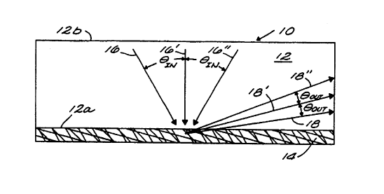
FIG. 1 is cross-sectional view of a multiplexed holographic optical structure
showing angular
multiplexing and steep trapping angles;
FIG. 2 is a cross-sectional view and illustrates an example of a steep angle
embodiment of the
holographic planar concentrator of the present invention;
FIG. 3 is a cross-sectional view illustrating an anguiarly and spatially
multiplexed holographic
optical structure showing angular spread of input and output rays;
FIG. 4 is a schematic diagram of an angularly multiplexed single wavelength
recording setup
2 0 used for fabricating the holographic planar concentrator (HPC) of the
present invention;
FIG. S is a schematic diagram of an angularly multiplexed multi-wavelength
recording setup
used for fabricating the holographic planar concentrator of the present
invention;
FIG. 6 is a top plan view illustrating an example of a spatially multiplexed
HPC, showing re-
gions with different grating vectors;
2 5 FIG. 7 is a top plan view illustrating a line focus IIPC with photovoltaic
(PV) cells attached to
one edge;
FIG. 8 is a top plan view illustrating a multiplexed focusing HPC-PV device;
FIG. 9 is a top plan view illustrating a point focus HPC device with fiber
optic lightguide;
FIG. 10 is a top plan view illustrating a spatially multiplexed HPC device,
depicting a noni-
3 0 maging approach to concentrating light;
FIG. 11 is an illustration of an HPC-solar hot water heater;
FIG. 12 is an illustration of an HPC-window, illustrating one possible
distribution of solar
spectral energy; and
FIG. 13 is a view of a building incorporating a plurality of HPC-windows of
the present inven-
3 5 tion.
4
CA 02294908 1999-12-15
WO 99/04296 PCT/US98/14774
BEST MODES FOR CARRYING OUT THE INVENTION
The holographic planar concentrator (HPC) of the present invention utilizes a
multiplexed
holographic structure (film) to diffract light into a planar highly
transparent plate, such as an inorganic
glass or an organic polymer, where it is confined by total internal reflection
(TIR). By "highly transpar-
ent" is meant a material with an internal transmission of at least 90% per 25
mm of thickness in the 350
to 1400 nm range of the solar spectrum. This multiplexed holographic film
stores a combination of an-
gular and spectral multiplexed structures designed to collect and guide TIR
light in the optical highly
transparent plate. Recoupling losses from the planar highly transparent plate
are reduced by forming
two or more regions in the holographic film that are spatially multiplexed or
by launching the light into
the highly transparent plate at a small trapping angle (less than about 5
degrees) or by employing a
combination of these two techniques. The volume reflection hologram is located
on the opposed surface
of the highly transparent plate from the incoming light.
A unique holographic fringe structure is formed by producing many fringe
patterns in a single
film. This is referred to as angular multiplexing and is a technique by which
many recording beams
pairs interfere to produce a holographic structure which will accept light
from a range of input angles
and output the light into a different range of angles inside a highly
transparent plate of similar refractive
index to the film.
In addition to angular multiplexing, spectral multiplexing using multiple
wavelengths is em-
2 0 ployed. Spectral multiplexing serves to increase the spectral bandwidth of
the HPC.
Spatial multiplexing may be used to prevent recoupling losses from subsequent
reflections off
of the multiplexed holographic optical structure (MHOS). This is achieved by
fabricating a plurality of
discreet regions of the MHOS with different grating vectors. Each region of
the MHOS will have mul-
tiple gratings and a range of hating vectors, with regions in front of the
advancing light having differ-
2 5 ent diffraction characteristics than the region the light initially came
from. Since the different regions
have grating vector ranges that differ substantially, the light confined in
the highly transparent plate is
not recoupled out of the HPC when it strikes a different region of the MHOS on
its way to the edge of
the highly transparent plate.
Recoupling losses may alternately be avoided by configuring the hologram to
launch optical
3 0 radiation into the highly transparent plate at a small trapping angle,
defined above as less than about S
degrees. This reduces the number of subsequent interactions with the
holographic film and reduces the
optical losses.
A. Holoeranhic medium
3 5 The holographic medium can be of any lrnown material type capable of
forming a volume
phase hologram. Several of the existing film material types include duPont's
Omnidex photopolymer
5
CA 02294908 1999-12-15
WO 99/04296 PCT/US98/14774
film, Polaroid's Mirage photopolymer material, dichromated gelatin, polyvinyl
carbozole-based photo-
polymer films, silver halide emulsions and any other holographic materials.
In addition, these films can be layered, with each layer having different
angular, spectral and
spatial multiplexed properties. This can take the form of two or more layers
of holographic film at
tached to the highly transparent plate. Each additional layer must be index-
matched in order to keep in
terfacial reflection from trapping light in the thin film layers which are
more absorbing than the highly
transparent plate.
The commercial holographic materials available from duPont and Polaroid have
existing
chemistries and processes which allow for the formation of nonuniform fringe
structures; dichromated
gelatin films also have the existing chemistry to form nonuniform fringe
structures. (Nonuniform fringe
structures are structures which have a variation in fringe spacing from the
front to the back of the film.)
In addition to these techniques, holographic structures can also be shrunk or
swelled utilizing optical
adhesives. This can be utilized when creating multilayer stacks of holographic
film, bonding the holo-
graphic film to the highly transparent plate or providing a protective layer
for the holo~~raphic film.
The HPC of the present invention relies on the combined techniques of angular,
spatial and
spectral multiplexing to accomplish its function, which is to concentrate
light. By combining these
techniques, the production of a unique MI-IOS is achieved.
l . Optical Losses
2 0 The HPC of the present invention requires that the holographic structure
be spatially multi-
plexed to avoid recoupling in order for the device to function.This is
completely different from the way
waveguide couplers work in waveguiding applications. The holographic waveguide
couplers used in the
coummunications industr~~ do not have to address subsequent passes through the
holographic structure
once the light is diffracted into the waveguide. Overcoming the recoupling
losses in the HPC is the pri-
mary reason for the complexity of the spatial multiplexing which embodies both
the angular and spec-
tral multiplexing in order to achieve the spatial multiplexing.
To reduce light losses in the structure, novel techniques are used to prevent
loss of optical en-
ergy. The highly transparent plate can be chosen to be any thickness, but for
practical purposes, it will
typically be in the thickness range of 1 to 1 S mm. Thicker highly transparent
plates begin to become
3 0 very costly and are not practical for the applications disclosed herein.
Given these limitations to plate
thickness and the goal of having the light advance through the HPC structure
with as few bounces as
possible, it is required that the internal diffracted wave vector angle be
sufficiently small so that the
light is diffracted more directly down the HPC structure. HPC structures with
a pathlength-to-thickness
ratio (PTR) between 25 and 200 are preferred. Pathlength is the greatest
distance the light collected by
3 5 the HPC has to travel in the HPC structure to reach the receiver location.
6
CA 02294908 1999-12-15
WO 99/04296 PCT/US98/14774
To make the HPC of the present invention work for the above pathlength to
thickness ratios,
many factors have to be taken into acount. The following is a list of the
techniques used in the HPC to
reduce optical losses:
1. Absorption of the light energy in the HPC structure comes from three
sources. The first is the ab-
sorption in the highly transparent plate. The material from which the highly
transparent plate is
made of is chosen to have low absorption in the spectral region from 350 to
1400 nm. By "low ab-
sorption" is meant an absorption less than 10% (the inverse of highly
transparent, defined above).
The second source of absorption is from the film layer, so it is important to
keep the film layers as
thin as possible and as transparent as possible. As used herein, the term
"thin" with respect to the
film layer means a thickness of less than 30 p.m, while the term "transparent"
with respect to the
film layer means an internal transmission of at least 90%. All of the films
discussed herein are of
sufficiently low absorption. The third source of absorption is the optical
adhesive if one is used.
Optical adhesives are available with very low absorption; such low absorption
optical adhesives are
preferred in the practice of the invention.
2. In order for the HPCs with the above PTR to collect light energy, the
internal diffracted wave vec-
for must be in the range of 1 to 40 degrees. A single grating will diffract a
large bandwidth of light,
with each wavelength in the spectral bandwidth diffracted with a different
wave vector angle. This
means that for a single grating, the chromatic angular spread can be larger
than desired. The large
spectral bandwidth for a single grating means that the light that is collected
has a chromatic angular
2 0 spread. An example of this is that a single grating with a 100 nm
bandwidth represents an angular
fanout of the collected light through a 30 degree angle. So as the bandwidth
of the device is in-
creased, a single grating structure would be self limiting, as the light from
the spectral bandwidth
would start to be lost because the internal diffracted wave vector would
exceed the TIR con6ne-
ment of the highly transparent plate. This means that by increasing bandwidth
in the HPC device, it
2 5 is necessary to multiplex the spectral component while keeping the angular
component within the
TIR trapping of the HPC. This can be accomplished by keeping the grating angle
constant and
varying the grating spacing in the multiplexed recordings. This is one
technique to increase band-
width and maintain the required internal diffracted wave vector within the TIR
confinement of the
HPC. This angular spread can be reduced by spectral multiplexing of the single
film, keeping the
3 0 fringe angle fixed for each multiplexed recording. Since index modulation
is shared between expo-
sores, the amount of energy that is collected is approximately the same and
the net result is that
more wavelengths of light can be collected and diffracted into a narrower
angular range. This
means that more energy will be concentrated to the receiver.
3. The HPC device of the present invention requires the combination of a
highly transparent plate with
3 5 a holographic film that has a good refractive index match to the highly
transparent plate. A close
refractive index match is required between the highly transparent plate and
film in order to effec-
7
CA 02294908 1999-12-15
WO 99/04296 PCT/US98/14774
tively diffract into the highly transparent plate without having large Fresnel
reflection at the highly
transparent plate/film interface. If the mismatch in refractive indices causes
a large amount of en-
ergy to be reflected at the interface, then the energy will be confined in the
film which has a signifi-
cantly larger absorption coefficient than the highly transparent plate. To
effectively move light en-
ergy from the film into the highly transparent plate the refractive index of
the film and highly trans-
parent plate have to be very close, within 3% of each other. This will
minimize the light traveling
more distance in the film. The film absorption is typically higher than the
highly transparent plate's
absorption, so the preferred embodiment of the device uses a close match in
refractive index to
minimize the thickness of film that the diffracted light has to pass through.
4. The recoupling of the internal diffracted light through subsequent
interactions with the holographic
film as the light bounces through the HPC structure is the largest optical
loss to overcome. This,
however, can be reduced or avoided altogether by spatially multiplexing the
holographic film por-
tion of the HPC structure. The spatial multiplexing is performed by laying out
a pattern of holo-
graphic optical elements (HOES) that each have slightly different spectral
andlor angular perform-
ance. The diffracted light of each spatially multiplexed region has different
internal diffracted wave
vector angles and a different spectral bandwidth related to those angles. HOES
have a direct link
between angle and wavelength, so it is truly the combination of the two that
determine if the spa-
tially multiplexed regions are all discrete in terms of their performance.
This discrete behavior
means that light coming from one region will not be diffracted by the HOES in
the subsequent re-
2 0 gions. The size of the multiplexed regions is a function of the pathlength-
to-thickness ratio, since
the number of bounces of light determines the number of required discrete
spatially multiplexed
regions. Again, the number of bounces is determined by the pathlength-to-
thickness ratio and the
internal diffracted wave vector.
B HiQhly Transparent Plate
The highly transparent plate of the HPC can be made from glass or polymer that
is optically
transparent. The term "highly transparent" is defined above; by optically
transparent is meant that the
glass or polymer plate is transparent as defined herein at least in the
wavelength region of about 350 to
1400 nm. The highly transparent plate can be any thickness or size. The
preferred material for the
3 0 highly transparent plate is low iron float glass that is chemically
enhanced to increase solar transmis-
sion. Preferred glass types include Solarphire glass and Starfire glass, both
available from PPG Indus-
tries, Inc. These glasses have internal transmittances of approximately 98%.
The highly transparent plate can have a flat or curved surface. Preferred
dimensions will be
dictated by application and size. One preferred embodiment utilizes low iron
glass that is 6 tnm thick.
3 5 In addition, it is important that the refractive index of the holographic
film and the highly transparent
plate be closely matched, preferably, to a refractive index difference of at
most about 3%, and more
8
CA 02294908 1999-12-15
WO 99/04296 PCT/US98/14774
preferably less than this value. The close matching allows for steep coupling
angles inside the highly
transparent plate.
In some cases, it is desired that the refractive index of the film be slightly
larger than the re
fractive index of the highly transparent plate, since there is a slight
advantage to having the refractive
index of the film being slightly larger than that of the glass if there is a
mismatch. The advantage mani
fests itself as a reduction in the Fresnel reflection losses at the interface,
hence improving coupling effi-
ciency compared with the highly transparent plate having a larger refractive
index than the film. How-
ever, this should not be construed as a limiting factor to the claims set
forth herein, since the device will
still work when implemented in either mode.
In choosing the highly transparent plate and film refractive indices, there
are a number of im-
portant parameters required for the HPC device to work effectively. The nature
of the HPC device lends
itself to many applications and hence many variations in the embodiment of the
device. It is the intent
and scope of this patent to include all variations of the holographic
structure described herein.
FIG. 1 depicts an example of the basic embodiment of the present invention, in
which the holo-
graphic planar concentrator 10 is shown comprising highly transparent plate 12
and holographic film
14. The holographic film 14 is mounted on the side 12a of the highly
transparent plate 12 opposite that
side 12b on which solar energy is incident.
Careful selection of the refractive indices of the highly transparent plate
and the holographic
film can allow for coupling of light into the highly transparent plate at very
steep angles as is shown in
2 0 FIG. 1. The light, represented by rays 16, 16' 16", is seen as entering at
an angle 6N and being coupled
into the highly transparent plate 12 at an angle Ao~, as rays 18, 18' 18",
respectively. The particular dif
fraction grating recorded, described in greater detail below, in the
holographic film 14 controls the an-
gle 60~,. As will be shown below, a wide acceptance angle 0;~ can be coupled
into the highly transparent
plate 12 as a smaller angle Oo~,.
2 5 An example of the foregoing is depicted in FIG. 2, in which the refractive
index of the holo-
graphic film 14 is chosen to be 0.001 greater than the refractive index of the
highly transparent plate 12.
This means that use of a 6 millimeter thick (t) highly transparent plate 12
and a trapping angle of 2 de-
grees results in an optical path length (1) of 343 millimeters before the
coupled light 18 will strike the
holographic film 14 for a second time; this combination provides a PTR of
57.2. This illustrates one
3 0 technique of avoiding recoupling losses in the HPC device 10. It is
understood that glass thickness and
trapping angle affect the effective size of the devices. The optical path
lengths discussed here allow for
many practical applications of the HPC technology.
In another embodiment of the present invention, the trapping angles are not
limited to small an-
gles but rather a combination of angles are used in a spatially multiplexed
approach, as is shown in FIG.
3 5 3. As indicated above, the phrase "small trapping angle" refers to an
angle of less than about S degrees.
9
CA 02294908 1999-12-15
WO 99/04296 PCT/US98/14774
The holographic film comprises a plurality of regions, denoted 14, 114, 214,
incident on each of
which are rays 16, 16', 16", as described above. Each region 14, 114, 214 has
a different diffraction
grating, resulting in a set of angles 60~, of light coupled into the highly
transparent plate 12 that can ei-
ther be identical to each other or different; however, the angle that the
middle ray 18', 1 I8', 218' of the
set makes to the plane defined by the holographic film 14 is different in each
case.
This spatial multiplexing technique allows for multiple reflections from the
holographic struc-
ture and hence larger trapping angles can be used. This approach reduces the
need for a close index
match between the highly transparent plate and the holographic film. As an
example, in a case using
very steep trapping angles, a very good match between the refractive index
differs by only 0.01% but
for a spatial multiplexed case, the refractive index may vary by up to 3.0%
for a worst match scenario.
Spatially multiplexing the multiplexed holographic optical structure (MHOS)
can produce HPC
devices with functionally longer optical path lengths, thus increasing the
functional size of the HPC
panels and increasing the number of applications that the HPC can be used for.
Spatially multiplexing
the HPC holographic structure will also avoid the limiting factor of beam
degeneracy when angularly
multiplexing and concentrating the gathered light. Beam degeneracy can also be
avoided by utilizing
the HPC device in a line focusing mode instead of a point focusing mode.
Material dispersion effects of the mismatch between the refractive indices of
the holographic
film and the highly transparent plate can be minimized by desigming the HPC
device to perform at a
wavelength where the refractive index of the glass matches that of the
holographic film. The differing
2 0 normal material dispersion will then cause a divergence of the refractive
indices of the glass and the
film at other wavelengths differing from the design wavelength. The effect of
dispersion on the overall
match of the refractive indices between the film and the glass is that the
index match really represents
an average match over the chosen spectral range.
2 5 ('-. Holographic Recordine Process
The HPC of the present invention is fabricated by attaching a holographic film
or films to one
side of an optical highly transparent plate. The holographic film is attached
to the side opposite of the
incoming light. Recording of the master MHOS is performed in an index matched
environment; these
techniques are lrnown by those skilled in this art. By "indexed matched
environment" is meant that an
3 0 appropriate material which is very transparent at the recording laser
wavelength and matched in refrac-
tive index to the film is used in such a geometry to allow propagation of the
laser beam into the film at
very steep angles. There have been many ways to bring laser beams into
materials at steep angles and
all require index matching. Different techniques utilize glass blocks, prisms
and fluids in tanks. This
technique is required for making the master hologram, but once the master is
made, it only requires in-
3 5 dex matching the film to be copied to the master plate. The replication
also requires that the recording
CA 02294908 1999-12-15
WO 99/04296 PCTIUS98/14774
be done in an index matched environment between master and copy, but it is a
simpler process for mass
production.
One embodiment can use a liquid gate or a tank filled with index matching
fluid in which the
hologram and attached highly transparent plate are placed for exposure, as
illustrated in FIG. 4. The re-
fractive index matching fluid in the tank should be within about 12% of the
refractive index of the
holographic film and the highly transparent plate. Preferably, a liquid with a
refractive index slightly
larger than the film and the highly transparent plate is employed. The better
the match between the liq-
uid and the highly transparent plate/film, the fewer noise gratings will be
formed.
FIG. 4 shows the HPC 10 comprising the highly transparent plate 12 and
holographic film 14
immersed in a tank 20 filled with a fluid 22 having substantially the same
refractive index as the highly
transparent plate 12. Object beams 22a - 22e are incident on the top surface
12b of the highly transpar-
ent plate 12, while reference beams 24a - 24e are incident on the exposed
surface 14a of the holo-
graphic film 14. The letters represent recording pair designation. The object
beams 22a - 22e and the
reference beams 24a - 24e are generated by techniques well-known in the art of
holographic recording
and do not form a part of this invention.
The index matching tank provides an environment which reduces the amount of
stray light
scattered from interfaces and other surfaces. This enhances the quality of the
MHOS by minimizing the
amount of optical noise in the recording process.
Multiple laser beams are used to record a unique holographic structure which
will accept light
2 0 from a range of input angles and direct the light down the optical highly
transparent plate. Once in the
optical highly transparent plate, the light is trapped so long as the light
does not encounter any subse-
quent interactions with the same holographic structure. The recording process
is a combination of an-
gular, spectral and spatial multiplexing and can be performed in many ways by
those skilled in the art.
Multiple pairs of laser beams are used with varying angles and different
wavelengths and can
2 5 have collimated, diverging, converging or a combination of wavefronts when
fabricating the HPC, as
shown in FIG. 5. Each pair of recording wavefronts has one object beam which
mimics one narrow
range of sun angles during the day and one reference beam which mimics the
desired playback (con
centrated) wavefront. There is no one preferred embodiment for the recording
geometry, since the de
sired playback location varies for a given application or position. Because
the mounting orientation of
3 0 the HPC and its installed location on the Earth will vary, the HPC has the
advantage of being recorded
for different input angular ranges and different spectral collection
requirements. To give an example,
the HPC can be mounted vertically or tilted to the desired latitude of
placement. In addition, the range
of input angles may be chosen to be very narrow or very large, depending on
the type of illumination
available and the desired output spectrum.
3 5 The beam recording geometries vary with the grating design. The input
angle range for, say,
one multiplexed film recorded at 676 nm and 514 nm laser wavelengths will be
plus or minus 35 de-
grees from the normal in the medium and 100 to 140 degrees from the normal in
the medium. Beam
11
CA 02294908 1999-12-15
WO 99/04296 PCT/CJS98/14774
pairs are selected from this range of angles for producing the desired
holographic structure to capture
and concentrate the desired solar energy for the given location and mounting
orientation. One preferred
embodiment uses two recording pairs with angles of 30 and 100 degrees for one
pair and -30 and 130
degrees for another pair.
While the HPC can be used in either passive or active tracking modes, the use
of angular multi-
plexing permits the use of passive tracking, which simplifies the overall
structure and reduces cost. As
an example of a preferred passive tracking embodiment, the HPC photovoltaic
panel is mounted tilted
to the latitude of installation and has the center angle of acceptance normal
to the HPC front surface.
The angular recording then mimics a variation of as much as approximately 160
degrees in the daily
sun angle and 45 degrees in the seasonal sun angle. This represents a
multitude of recording pairs, each
launching their object beams at approximately 10 degree intervals.
As indicated above, the hologram that is recorded includes angular and
spectral multiplexing.
Spatial multiplexing is achieved by defining different regions in the
holographic film, as described in
greater detail below, and using the process depicted in FIG. 5 to record the
angular and spectral multi-
plexing in each region. Light coupled into the highly transparent plate 12 in
one spatial region thus does
not interact with the holographic film 14 in another spatial region. The use
of the combination of re-
gions essentially avoids recoupling losses resulting from multiple
interactions of the holographic film
by the light confined in the highly transparent plate. This spatial
multiplexing approach results in higher
efficiency and the ability to create larger HPC devices.
2 0 The MHOS can be recorded with gaussian or nongaussian beam profiles. The
use of different
beam profiles allow for control of the exposure intensity across the
holographic film. This translates
into control over the diffraction efficiency of the final MHOS. Intensity of
the laser energy across the
holographic film is important in controlling the playback efficiency of the
MHOS, since the quality of
the holographic recording is determined in pan by the intensity of the
exposure energy striking the
2 5 holographic film. The intensity of the recording energy across the film
should be substantially uniform,
by which is meant a variation in intensity of not more than about ~10 percent.
Different holographic
film materials require different exposure conditions and are more sensitive to
exposure intensity. The
uniformity of not more than about ~10 percent is a guideline to successfully
fabricating HPC devices
and is not necessarily the ideal exposure uniformity for every type of
holographic film material.
3 0 The HPC 10 can also be fabricated using more than one layer of holographic
film. By utilizing
diffractive holographic structures, multiple layers can be used. Essentially,
blue photons only interact
with the MHOS sensitized to the blue portion of the solar spectrum and the red
photons only interact
with the film sensitized to the red part of the solar spectrum.
Holographic reflective structures have the ability to be fabricated in a range
of spectral per-
3 5 formance from very narrow (a few nanometers) to very broad (several
hundred nanometers). This al-
12
CA 02294908 1999-12-15
WO 99/04296 PCT/US98/14774
lows for the tailoring of the reflective holographic film with a spectral
bandwidth of chosen size within
these bounds.
D Multiplexed Holographic Optical Structure
1. Angular multiplexine
The HPC of the present invention uses angular multiplexing to achieve a
multitude of reflection
type volume phase holograms in a single film. Many techniques exist for
angularly multiplexing and
are known to those skilled in the art. The preferred embodiment utilizes
collimated and diverging re-
cording wavefronts, although converging wavefronts may also be used. The
wavefronts are directed
from opposite sides of the holographic film to produce a reflection-type
volume phase holographic
structure, as shown in FIGS. 4 and 5. In addition, the polarization of the
wavefronts can be chosen to
achieve a maximum fringe contrast.
The MHOS can be created utilizing several different wavelengths of laser light
or a single
wavelength with the recording angles adjusted to play back at the desired
wavelengths. Single wave-
length recording can be used to simulate multispectral recording by adjusting
recording angles of the
multiplexed reference and object beams such that a recording beam at one angle
is designed to play-
back at a different angle and different wavelength. This is due to the
relationship between angle and
wavelength in diffractive structures. In addition, more than one holographic
film can be used if required
and applied over the first holographic film. The additional films can be used
for increasing angular per-
2 0 formance or broadening the spectral bandwidth of the HPC .
Angularly multiplexing a single wavelength can result in an angular
performance at the re-
cording wavelength but also at other wavelengths with a different angular
performance. The net effect
is a single wavelength recording with enhanced spectral characteristics.
2 S 2. Spectral Multinlexin~
To increase the spectral bandwidth of the HPC devices, the spectral
sensitivity of the MHOS
can be enhanced using techniques known in the art. The holographic structure
can be recorded with
multiple laser wavelengths as well as multiple angular inputs. Recording with
multiple wavelengths has
the advantage of increasing the spectral sensitivity of the MHOS. In addition
to recording with multiple
3 0 wavelengths, it is also possible to nonlinearly shrink or swell the MHOS;
this results in a series of
fringes with varying spacing. The fringes with varying spacing has the effect
of increasing the spectral
bandwidth of the HPC device.
3. Spatial Multiplexins
3 5 Each region of the MHOS has multiple gratings and a range of grating
vectors. The different
regions have grating vector ranges that differ substantially so that the light
confined in the highly trans-
parent plate is not recoupled out of the HPC when it strikes regions of the
MHOS on its way to the edge
13
CA 02294908 1999-12-15
WO 99/04296 PCTlUS98/14774
12' of the highly transparent plate 12, as shown in FIG. 6, which is a top
plan view. FIG. 6 shows an ex-
ample of a spatially multiplexed HPC 10, with each region 26a - 26d with
different grating vectors, re-
sulting in coupled light 18a - 18d incident on the edge I2' at different
angles.
To avoid recoupling losses from subsequent reflections from the MHOS, a
spatial multiplexing
approach is used. In this embodiment of the HPC, the MHOS is divided into many
different regions,
with the regions in front of the advancing light having a different Bragg
angle than the light striking
that region as shown in FIG. 3. This technique prevents recoupling losses,
since the subsequent reflec-
tions from the MHOS for light that is confined to the highly transparent plate
strikes a holographic
structure which has a substantially different grating vector than the spatial
region from which the light
was initially diffracted.
4. Additional Considerations
The combination of the highly transparent plate 12 and the holographic film 14
regions physically
form the total light trapping structure 10. The reason that the spatial
multiplexing is required in the MHOS
is because the light 18 has to pass through the holographic film 14 and bounce
off the air/film interface to
continue to be confined in the structure 10 by TIR. The light 18 is required
to remain in the total structure
10 in order to be delivered to the receiver 30, 32. The close refractive index
match required to launch the
light 16 into the glass or polymer highly transparent plate 12 ensures that
the light bounces back through
the film 14 to the film/air interface. The present invention requires a fairly
large area and hence long path-
2 0 lengths to be a good solar collector. This is discussed above with regard
to the particular example in con-
nection with FIG. 2, describing 6 mm thick glass with a pathlength of 343 mm.
Any angle that is larger
will be required to pass through the film 14 an additional one or more times.
The spatial multiplexing al-
lows for regions 14, 114, 214 to have different holographic performance and
hence not interact with the
advancing light from a previous holographic region.
E. Focusing
The HPC can be designed to concentrate light in two dimensions, essentially a
line focus (FIG.
7) or in three dimensions, essentially a point focus (FIGS. 8 and 9). In FIG.
7, the coupled rays 18 are
incident on a photovoltaic cell 30 mounted along the edge 12' of the highly
transparent plate 12. In
3 0 FIGS. 8 and 9, the coupled rays 18 are focused onto a light-receiving
device, such as the photovoltaic
cell 30 (FIG. 8) or a fiber optic lightguide 32 (FIG. 9).
This ability to concentrate light in two or three dimensions gives the HPC of
the present inven-
tion the ability to create a focal region which is a square or rectangular
region of any size, depending on
the thickness of the highly transparent plate and the amount of focusing
incorporated into the hoio-
3 5 graphic structure. The focusing can be accomplished with imaging or
nonimaging techniques, The
nonimaging technique produces a square or rectangular region due to the
subsequent intemai reflections
in the highly transparent plate. 'The imaging technique can be used to produce
focal regions of varying
14
CA 02294908 1999-12-15
WO 99/04296 PCT/US98/14774
shapes such as circular or elliptical focal regions. The two techniques can
also be combined to produce
focal regions with the combined geometric properties of nonimaging and imaging
focal regions. In ad-
dition to the overall shape of the focal region, the intensity distribution in
the focal plane can be ad-
justed using either the imaging or nonimaging recording techniques. This
allows for more design free-
dom in the utilization of the concentrated light.
One embodiment utilizes the spatial multiplexing approach combined with
collimated recording
beams to produce a tiled holographic structure of regions 26 the same size as
the focal region 12' (FIG.
10). The collimated playback beams 18 from each tile 26 of the holographic
structure sum at the focal
region 12' to produce a concentration of the incoming light. This technique
allows for the design of
HPC devices that can avoid recoupling losses by designing the layout of the
holographic regions such
that the location and grating vector of the region avoids the recoupling of
light out of the wave-guide
12. The lines 34 normal to the light propagation vector 18 represent a flat
collimated wavefront.
F. Device Operation
The holographic planar concentrator of the present invention functions like a
conventional two-
stage concentrator that has been folded into the plane of the collecting
device. Incoming light from a
range of acceptance angles passes through the optical highly transparent plate
and is reflected/diffracted
by the multiplexed holographic structure trapping the light in the plate and
guiding it to one edge of the
plate or to a focal region on the edge of the plate. In addition, larger
plates with several HPC holo-
2 0 graphic structures can be produced with multiple focal regions on
different sides of the plate or focused
into the corners of the plate. This basic scheme of operation can be used as
the fundamental building
block for many applications. When combined with a photovoltaic device or a
fiber optic lightguide, the
HPC of the present invention becomes an energy generating or energy
redirecting product (FIGS. 7-9).
One of the primary advantages of the HPC device over conventional
concentrators is its ability
2 5 to gather light from a large range of input angles while being mounted in
a stationary (non-tracking)
configuration. To achieve this ability, the HPC device utilizes a multiplexed
holographic structure along
with the TIR trapping of the highly transparent plate. This two-stage
concentrator approach works
similarly to some nonimaging optic concentrators which rely on TIR confinement
of light. It is the
combination of the unique multiplexed holographic structure and the TIR
confinement which combine
3 0 into the novel light concentrator of the present invention. The HPC has
many advantages in terms of
ease of fabrication and low material cost.
Further, the HPC can be used to collect either direct light from the sun or
diffuse light, such as
light on cloudy days or light reflected from the surrounding environment. The
HPC is intended to col-
lect substantially all of the solar spectrum, particularly in the range of
about 350 to 1400 nm.
3 5 The four primary applications for the HPC products are (1) solar electric
power generation, (2)
daylighting with natural sunlight, (3) thermal heating, and (4) windows which
combine any or all of the
CA 02294908 1999-12-15
WO 99/04296 PCT/US98/14774
three previous applications along with, optionally, the filtering of
ultraviolet and infrared energy from
sunlight. The four primary application are described below.
1. HPC-Photovoltaic Panel
The first device utilizes a photovoitaic cell to convert the concentrated
light to electricity.
FIGS. 7 and 8 depict this embodiment. Any number of different photovoltaic
conversion devices can be
used and the output spectrum of the HPC can be engineered to more closely
matched the bandgap of the
conversion device to reduce the cooling required on the photovoltaic cell.
The HPC photovoltaic (PV) panel utilizes the HPC with a PV cell to convert the
light gathered
by the HPC into electricity. The PV cell is directly bonded to the edge of the
highly transparent plate, as
shown in FIG. 7, creating an integrated PV panel. One embodiment (FIG. 7) has
the entire edge 12' of
the HPC 10 covered with one or more PV cells 30. Other embodiments utilize a
point focus HPC device
10 and a PV cell 30 mounted on the corner or side 12' of the highly
transparent plate 12, such as shown
in FIG. 8). The advantages of the HPC-PV panel include the following:
1. Passive tracking concentrator.
2. Two-stage light trapping.
3. Multiple panel embodiments, flexible in design.
4. Selective bandwidth capability to minimize waste heat, design feature.
5. Transparent HPC allows for additional films or collection devices behind
the PV panel,
2 0 hence minimizing costs associated with structural requirements and land
requirements.
6. Monoiithic PV arrays mounted at focal point.
7. Utilization of series-connected cells possible due to uniform illumination
at collection area;
this is a result of the nonimaging behavior of the HPC concentrator.
2 5 2. HPC-Skvli~ht
In another application of the HPC technology, a fiber optic cable 32 is bonded
to the edge of the
HPC at the focal point of the concentrated light, as shown in FIG. 9. The
light 18 is launched directly
into the fiber optic lightguide 32. Other embodiments can include additional
optics to improve the cou-
pling efficiency between the HPC and the lightguide. The advantages of the HPC-
skylight include:
3 0 1. Passive tracking concentrator.
2. Collection and launching of light into a fiber optic lightguide.
3. Selective bandwidth to launch only the desired light into the fiber optic
for illumination pur-
poses.
16
CA 02294908 1999-12-15
WO 99/04296 PCT/US98/14774
3. HPC-Hot Water Heater
A variation on the HPC-Skylight embodiment uses the light concentrated into
the fiber optic
lightguide to heat water for domestic hot water applications. This embodiment
is depicted in FIG. 1 l,
which shows the fiber optic lightguide 32 secured to the edge 12' of the
highly transparent plate 12.
Solar energy 18 is thus guided into a conventional hot water tank 36 filled
with water 38. The solar
spectrum is confined and absorbed within the hot water tank, thereby either
heating the water directly
(wavelengths absorbed by water molecules) or indirectly (wavelengths absorbed
by hot water tank liner
and re-radiated into the water). The advantages of the HPC-hot water heater
include:
1. Passive tracking concentrator.
2. Collection and launching of light into a fiber optic lightguide.
3. Selective bandwidth to launch only the desired light into the fiber optic
for heating water.
4. HPC-Window
'fhe HPC window is yet another embodiment of the invention and combines the
features of the
other applications with the ability to filter ultraviolet and infrared light.
FIG. 12 depicts one embodi
ment of the HPC window 10, with several edges, denoted here as 12', 112', and
212'. A photovoltaic cell
30 is attached to edge 12', and, if it is a silicon PV cell, absorbs radiation
in the region of about 700 to
1100 nm. A first fiber optic lightguide 32 attached to edge 112' is used to
guide visible light (in the re-
gion of about 400 to 700 nm} into the interior of a building (not shown) to
the side of which the window
2 0 10 is attached, to provide a natural source of light. A second fiber optic
lightguide 132, attached to edge
212', is used to guide primarily infrared energy in the region of about 700 to
1400 nm to a hot water
tank 36 for heating the water 38 therein. Ultraviolet light (not shown) in the
region of about 350 to 400
nm incident on the front surface 12b of the window 10 is blocked from passing
through the window by
the particular structure of the holographic film 14 (not shown in FIG. 12),
attached to the back surface
2 5 of the window; a suitable holographic grating and/or a UV-blocking
component in the holographic film
could be used, for example.
The HPC window 10 shown in FIG. 12 is merely exemplary, and it will be
appreciated by those
skilled in this art that other devices and other combinations thereof may be
employed to utilize various
portions of the solar spectrum and/or block undesired portions thereof from
passing through the window
3 0 10. The advantages of the HPC-window include:
1. Control of solar gain through the window.
2. Control of ultraviolet and infrared energy transmission.
3. Passive tracking concentrator.
4. Collection and launching of light into a lightguide.
3 5 5. Generation of electricity with photovoltaic devices.
6. Collection of energy for heating applications possible.
7. Selective spectral and angular bandwidths.
17
CA 02294908 1999-12-15
WO 99/04296 PCT/US98/14774
FIG. 13 depicts a building 38 employing a plurality of HPC windows 10, used
with one or more
of the devices described above. Further, skylights 40 or separate solar panels
42 comprising the HPC
window 10, either roof mounted or, in the case of solar panels, ground-
supported, may be utilized. The
solar panels 42 may use either totally passive tracking or active tracking
mechanisms, which are well-
s known in the art and thus not shown here. The HPC windows 10 may be employed
on the east, south,
and west sides of the building 38 for collection of both direct and indirect
solar radiation and on the
north side of the building (in the northern hemisphere) or on the south side
of the building (in the south-
ern hemisphere) for collection of indirect solar radiation.
E?tAMPLES
Devices comprising a multiplexed (angular and spectral) holographic film
bonded to a glass
plate have been fabricated with large angular acceptance. One experiment
utilized three angular and
three spectral multiplexed beams with a calculated light gathering efficiency
of 20 percent. The angular
performance of the devices was 160 degrees in the daily solar angular
variation and 45 degrees in the
seasonal angular variation.
In addition, larger spatially-multiplexed devices were made that utilized
different holographic
structures to reduce recoupling losses. The devices concentrated light to one
edge of the glass plate. The
spatially-multiplexed holographic structure varied from the region of the
plate farthest from the edge
2 0 that the light was concentrated to the region of the plate adjacent the
edge that the light was concen-
trated to.
The largest device constructed to date is a 12 by 8.5 inch highly transparent
acrylic plate, 6 mm
thick with an active area of 8 by 8 inches (64 square inches). It utilized 3
layers of DuPont holographic
film each layer representing a different spectral range (spectral
multiplexing). The films were adhered
2 5 with Norland NOA 65 optical adhesive. Each layer of holographic film had
44 different spatially multi-
plexed regions and each film was recorded using four multiplexed angular
beams. Each spatial region
was 50 mm by 15 mm. The regions varied from the output edge of the device
linearly to the opposite
edge of the HPC. The device showed a total solar collection efficiency of 2
percent at the optimum an-
gle and calculated efficiency of 20 percent in the narrow wavelength band that
it was recorded in 490 to
3 0 530 nanometers. It was constructed as a line focus HPC device.
Another example of a preferred embodiment utilized a piece of 4 x 12 inch, 6
mm thick, low
iron Solarphire glass with 2 layers of Dupont Omnidex holographic film adhered
to the glass with Nor-
land NOA 65 optical adhesive. In the two layers of holographic film were
multiplexed a total of 6 re-
gions. These regions were angularly, spectrally, and spatially multiplexed.
One film contained regions
3 5 spatially multiplexed recorded at 500 nm, 568 nm, and 676 nm all with
fringe angles of 37 degrees. The
second film layer contained regions recorded at 500 nm, 568 nm, and 676 nm
with a fringe angle of 40
18
CA 02294908 1999-12-15
WO 99/04296 PCT/US98/14774
degrees. This device performed with a collection efficiency of 13% total solar
and 90% efficient in the
desired collection bandwidth.
While the above description contains many specific details, these should not
be construed as
limitations on the scope of the invention, but rather as an exemplification of
one preferred embodiment
thereof. Many other variations are possible. For example, a single holographic
film sensitized for full
color recording will allow spectral multiplexing in one film and it can be
angularly multiplexed with 32
recording beam pairs, one pair per S degree of daily solar sun angle
variation. The film can then be
nonuniformly swelled to increase spectral bandwidth. Another variation may use
only a few angularly
multiplexed beams to only gather light for a limited number of hours per day.
This, too, can utilize full
color recording film and nonuniform swelling. Accordingly, the scope of the
invention should be de-
termined not by the embodiment illustrated, but by the appended claims and
their legal equivalents.
19