Language selection

Search

Patent 2295033 Summary

Third-party information liability

Some of the information on this Web page has been provided by external sources. The Government of Canada is not responsible for the accuracy, reliability or currency of the information supplied by external sources. Users wishing to rely upon this information should consult directly with the source of the information. Content provided by external sources is not subject to official languages, privacy and accessibility requirements.

Claims and Abstract availability

Any discrepancies in the text and image of the Claims and Abstract are due to differing posting times. Text of the Claims and Abstract are posted:

  • At the time the application is open to public inspection;
  • At the time of issue of the patent (grant).
(12) Patent: (11) CA 2295033
(54) English Title: A WIRE MESH CONVEYOR BELT
(54) French Title: BANDE TRANSPORTEUSE MAILLEE METALLIQUE
Status: Expired and beyond the Period of Reversal
Bibliographic Data
(51) International Patent Classification (IPC):
  • B65G 15/56 (2006.01)
  • B65G 15/54 (2006.01)
  • B65G 17/06 (2006.01)
(72) Inventors :
  • FRODERBERG, INGEMAR (Sweden)
(73) Owners :
  • FRIGOSCANDIA EQUIPMENT AB
(71) Applicants :
  • FRIGOSCANDIA EQUIPMENT AB (Sweden)
(74) Agent: SMART & BIGGAR LP
(74) Associate agent:
(45) Issued: 2007-08-28
(86) PCT Filing Date: 1998-06-22
(87) Open to Public Inspection: 1998-12-30
Examination requested: 2003-04-03
Availability of licence: N/A
Dedicated to the Public: N/A
(25) Language of filing: English

Patent Cooperation Treaty (PCT): Yes
(86) PCT Filing Number: PCT/SE1998/001202
(87) International Publication Number: SE1998001202
(85) National Entry: 1999-12-21

(30) Application Priority Data:
Application No. Country/Territory Date
08/880,860 (United States of America) 1997-06-23

Abstracts

English Abstract


A conveyor belt comprises a plurality of side links at each side of the
conveyor belt, a plurality of transverse rods connecting the
side links in pairs, and a wire mesh forming a conveying surface of the
conveyor belt. The wire mesh further comprises a plurality of
wire spirals each spiral having loops encircling two of the transverse rods.
At least some of the wire spirals have a varying pitch along the
length of the rods.


French Abstract

L'invention concerne une bande transporteuse comprenant, de chaque côté, une pluralité de maillons latéraux. Une pluralité de barres transversales relient les maillons latéraux par paires et un treillis métallique forme la surface de transport de la bande transporteuse. Le treillis métallique comprend également une pluralité de spirales, chaque spirale ayant des boucles encerclant deux des barres transversales. Au moins certaines spirales ont un pas variable sur la longueur des barres transversales.

Claims

Note: Claims are shown in the official language in which they were submitted.

5
CLAIMS:
1. A conveyor belt comprising
a plurality of side links at each side of the
conveyor belt,
a plurality of transverse rods connecting the side
links in pairs, and
a wire mesh forming a conveying surface of the
conveyor belt, said wire mesh comprising a plurality of wire
spirals each spiral having loops encircling two transverse
rods,
wherein at least some of said wire spirals have a
varying pitch along the length of said rods,
wherein the pitch of each spiral is smaller in a
first longitudinal part of the conveyor belt than in the
rest of the conveyor belt,
wherein said first part is a central part of the
conveyor belt.
2. A conveyor belt as claimed in claim 1, wherein the
pitch of each spiral in said central part is substantially
equal to twice the diameter of the wire.
3. A conveyor belt as claimed in claim 1, wherein the
length of the loops in said first part is smaller than the
length of the loops in the rest of the conveyor belt.
4. A conveyor belt as claimed in claim 1, wherein the
length of the loops on one side of said first part increases
towards the side edge of the conveyor belt.

6
5. A conveyor belt as claimed in claim 1, wherein the
loops in said first part are wound around the transverse
rods in alternating directions.
6. A conveyor belt as claimed in claim 5, wherein all
the loops in the rest of the conveyor belt are wound in the
same direction around the transverse rods.
7. A conveyor belt as claimed in claim 1, wherein all
the loops of the wire mesh are wound in the same direction
around the transverse rods.
8. A conveyor belt as claimed in claim 1, wherein
said varying pitch increases from one side edge of the
conveyor belt to the other side edge of the conveyor belt at
least over portions of said transverse rods.

Description

Note: Descriptions are shown in the official language in which they were submitted.


CA 02295033 1999-12-21
WO 98/58858 PCT/SE98/01202
1
A WIRE IvIESH CONVEYOR BELT
The present invention relates to a conveyor belt
which comprises a plurality of side links at each side of
the conveyor belt, a plurality of transverse rods
connecting the side links in pairs, and a wire mesh
forming a conveying surface of the conveyor belt, said
wire mesh comprising a plurality of wire spirals each
spiral having loops encircling two transverse rods.
Conveyor belts of this type are used in many belt
conveyors, especially in the food industry. They are
advantageous for inter alia treatirig of food products by
air in cooling, freezing or cooking the food products.
The conveyor belts may be designed to follow a
straight path, a helical path forming a stack of
helically wound tiers, or any other path. Normally,
separate side links and/or central links joining
consecutive transverse rods are used for taking up
tractive forces exerted on the conveyor belt so as to
move the conveyour belt forward.
However, this known design leads to a concentration
of the tractive forces to said links which therefore tend
to be relatively bulky. Also, the load on the transverse
rods via any central links will inevitably be concen-
trated and thereby require greater dimensions of these
rods than otherwise would be necessary.
Also, the resistance of the conveyor belt against an
air flow directed vertically through the conveyor belt,
varies over the width thereof when the conveyor belt
follows a lateral curve, e.g. along a helical path. This
is a consequence of an increasing collapse of the wire
spirals towards the inner side of the curve and results
in a varying cooling, heating or drying of the products

CA 02295033 1999-12-21
WO 98/58858 PCT/SE98/01202
carried by the conveyor belt in dependence of their
position laterally thereon.
A main object of the present in'Jention is to provide
a conveyor belt which enables an almost arbitrary distri-
bution of the tractive load across the conveyor belt.
A further object of the present i.nvention is to
provide a conveyor belt having a re.sistance against
vertical air flow which varies in, a predetermined manner
across the width of the convevor beit.
These objects may be attained in that the pitch of
each wire spiral is made to vary alonq the length of the
transverse rods.
In many applications, the -Lractive load should be
absorbed at a specific part alona the width of the
conveyor belt. The present invention satisfies that need
by making the pitch of each spiral smaller in that
specific part of the convevor belt than in the rest of
the conveyor belt.
Especially, the load shoulci be absorbed at a central
part of the conveyor belt or also at several parts across
the width of the conveyor belt.
Preferably, the pitch of the wire spiral at that
part or parts where the load should be absorbed is made
substantially equal to twice the diameter of the wire.
This enables a maximum force transfer between two
adjacent transverse rods without any component of the
force acting in the direction of the transverse rods and
therebv tending to displace the wire spiral in that
direction.
In order to further auarantee that the traction load
forces are absorbed at a desired part, the length of the
loops of that part is made smaller in the longitudinal
direction of the conveyor belt than the length of the
loops of the rest of the convevor belt in the same direc-
tion.

CA 02295033 2006-06-09
22055-217
2a
In accordance with this invention, there is
provided a conveyor belt comprising a plurality of side
links at each side of the conveyor belt, a plurality of
transverse rods connecting the side links in pairs, and a
wire mesh forming a conveying surface of the conveyor belt,
said wire mesh comprising a plurality of wire spirals each
spiral having loops encircling two transverse rods, wherein
at least some of said wire spirals have a varying pitch
along the length of said rods, wherein the pitch of each
spiral is smaller in a first longitudinal part of the
conveyor belt than in the rest of the conveyor belt, wherein
said first part is a central part of the conveyor belt.

CA 02295033 1999-12-21
WO 98/58858 PCT/SE98/01202
3
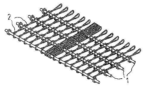
FIG. 1 is a perspective view of a section of a
conveyor belt according to an embodiment of the present
invention.
FIG. 2 is a plan view of the conveyor belt section
illustrated in FIG. 1.
The conveyor belt embodiment shown in FIGS. 1 and 2
has a plurality of transverse rods 1. The transverse rods
1 are connected to each other by means of side links (not
shown), and a plurality of wire spirals 2 are wound
around the transverse rods 1.
Each wire spiral 2 has a flattened helical form and
is wound around two adjacent transverse rods 1 in one
direction. The pitch of each wire spiral _2 is the same
across the width of the conveyor belt except for at a
central part of the conveyor belt where the wire spiral 2
has a much smaller pitch over four complete loops around
the two adjacent transverse rods 1 which are encircled by
the wire spiral 2. More precisely, the pitch in this
central part is approximately equal to twice the diameter
of the wire forming the wire spiral 2. This pitch is the
smallest possible pitch when each wire spiral intermeshes
with the wire spiral 2 on either side thereof, i.e. when
the half-turns of one wire spiral over one transverse rod
intermeshes with the half-turns of one adjacent spiral
over the same transverse rod.
Obviously, the smaller the pitch of a complete loop
of a wire spiral is, the more efficient is that loop in
transferring traction forces between the transverse rods
encircled, i.e. in the longitudinal direction of the
conveyor belt, because the direction of the traction
forces almost coincides with this longitudinal direction.
This efficiency may be further enhanced by reducing the
width of the wire spiral in the longitudinal direction of
the conveyor belt, i.e. reducing the length of the loops.

CA 02295033 1999-12-21
WO 98/58858 PCT/SE98/01202
4
Also, the traction forces when more or less parallel
with the longitudinal direction of the conveyor belt,
have small components in the direction of the transverse
rods tending to displace the turns of the wire spiral
along the transverse rods encircled by that wire spiral
out of their original positions.
It is to be understood that the r_,itch of the wire
spirals may be varied depending upon the needs in each
specific applicatiori and, inter alia, may include several
parts across the width of the conveyor belt each having a
separate, constant pitch, but may also include a conti-
nously varying pitch across the conveyor belt.
Moreover, by varvinq the pitch of the wire spirals
it is possible to provide a desired distribution across
the width of the conveyor belt of the resistance towards
air flow through the conveyor belt, especielly along
laterally curved parts of the conveyor belt path.
A variety of modifications of the conveyor belt
described above are possible within the scope of the
invention as defined in the appended claims.
Thus, where the transverse rods do not need to shift
position in the longitudinal direction of the conveyor
belt, e.g. in the central part of the conveyor belt, the
consecutive loops may be wound in opposite directions
around the transverse rods.
Also, the loops on one side of said first part of
the conveyor belt could increase towards the side edge of
the conveyor belt.

Representative Drawing
A single figure which represents the drawing illustrating the invention.
Administrative Status

2024-08-01:As part of the Next Generation Patents (NGP) transition, the Canadian Patents Database (CPD) now contains a more detailed Event History, which replicates the Event Log of our new back-office solution.

Please note that "Inactive:" events refers to events no longer in use in our new back-office solution.

For a clearer understanding of the status of the application/patent presented on this page, the site Disclaimer , as well as the definitions for Patent , Event History , Maintenance Fee  and Payment History  should be consulted.

Event History

Description Date
Time Limit for Reversal Expired 2015-06-22
Letter Sent 2014-06-23
Grant by Issuance 2007-08-28
Inactive: Cover page published 2007-08-27
Inactive: Final fee received 2007-06-05
Pre-grant 2007-06-05
Notice of Allowance is Issued 2007-04-18
Letter Sent 2007-04-18
Notice of Allowance is Issued 2007-04-18
Inactive: Approved for allowance (AFA) 2007-03-16
Amendment Received - Voluntary Amendment 2006-06-09
Inactive: IPC from MCD 2006-03-12
Inactive: S.30(2) Rules - Examiner requisition 2005-12-13
Inactive: IPC assigned 2005-11-24
Letter Sent 2003-05-14
Amendment Received - Voluntary Amendment 2003-05-05
Request for Examination Received 2003-04-03
Request for Examination Requirements Determined Compliant 2003-04-03
All Requirements for Examination Determined Compliant 2003-04-03
Inactive: Cover page published 2000-02-29
Inactive: First IPC assigned 2000-02-25
Letter Sent 2000-02-10
Inactive: Notice - National entry - No RFE 2000-02-10
Application Received - PCT 2000-02-04
Application Published (Open to Public Inspection) 1998-12-30

Abandonment History

There is no abandonment history.

Maintenance Fee

The last payment was received on 2007-05-31

Note : If the full payment has not been received on or before the date indicated, a further fee may be required which may be one of the following

  • the reinstatement fee;
  • the late payment fee; or
  • additional fee to reverse deemed expiry.

Patent fees are adjusted on the 1st of January every year. The amounts above are the current amounts if received by December 31 of the current year.
Please refer to the CIPO Patent Fees web page to see all current fee amounts.

Owners on Record

Note: Records showing the ownership history in alphabetical order.

Current Owners on Record
FRIGOSCANDIA EQUIPMENT AB
Past Owners on Record
INGEMAR FRODERBERG
Past Owners that do not appear in the "Owners on Record" listing will appear in other documentation within the application.
Documents

To view selected files, please enter reCAPTCHA code :


To view images, click a link in the Document Description column. To download the documents, select one or more checkboxes in the first column and then click the "Download Selected in PDF format (Zip Archive)" or the "Download Selected as Single PDF" button.

List of published and non-published patent-specific documents on the CPD .

If you have any difficulty accessing content, you can call the Client Service Centre at 1-866-997-1936 or send them an e-mail at CIPO Client Service Centre.


Document
Description 
Date
(yyyy-mm-dd) 
Number of pages   Size of Image (KB) 
Representative drawing 2000-02-28 1 24
Abstract 1999-12-20 1 56
Description 1999-12-20 4 164
Drawings 1999-12-20 1 51
Claims 1999-12-20 2 48
Claims 2006-06-08 2 47
Description 2006-06-08 5 182
Representative drawing 2007-08-01 1 31
Notice of National Entry 2000-02-09 1 195
Courtesy - Certificate of registration (related document(s)) 2000-02-09 1 115
Reminder - Request for Examination 2003-02-24 1 120
Acknowledgement of Request for Examination 2003-05-13 1 174
Commissioner's Notice - Application Found Allowable 2007-04-17 1 162
Maintenance Fee Notice 2014-08-03 1 172
PCT 1999-12-20 7 255
Correspondence 2007-06-04 1 38