Sélection de la langue

Search

Sommaire du brevet 2295033 

Énoncé de désistement de responsabilité concernant l'information provenant de tiers

Une partie des informations de ce site Web a été fournie par des sources externes. Le gouvernement du Canada n'assume aucune responsabilité concernant la précision, l'actualité ou la fiabilité des informations fournies par les sources externes. Les utilisateurs qui désirent employer cette information devraient consulter directement la source des informations. Le contenu fourni par les sources externes n'est pas assujetti aux exigences sur les langues officielles, la protection des renseignements personnels et l'accessibilité.

Disponibilité de l'Abrégé et des Revendications

L'apparition de différences dans le texte et l'image des Revendications et de l'Abrégé dépend du moment auquel le document est publié. Les textes des Revendications et de l'Abrégé sont affichés :

  • lorsque la demande peut être examinée par le public;
  • lorsque le brevet est émis (délivrance).
(12) Brevet: (11) CA 2295033
(54) Titre français: BANDE TRANSPORTEUSE MAILLEE METALLIQUE
(54) Titre anglais: A WIRE MESH CONVEYOR BELT
Statut: Périmé et au-delà du délai pour l’annulation
Données bibliographiques
(51) Classification internationale des brevets (CIB):
  • B65G 15/56 (2006.01)
  • B65G 15/54 (2006.01)
  • B65G 17/06 (2006.01)
(72) Inventeurs :
  • FRODERBERG, INGEMAR (Suède)
(73) Titulaires :
  • FRIGOSCANDIA EQUIPMENT AB
(71) Demandeurs :
  • FRIGOSCANDIA EQUIPMENT AB (Suède)
(74) Agent: SMART & BIGGAR LP
(74) Co-agent:
(45) Délivré: 2007-08-28
(86) Date de dépôt PCT: 1998-06-22
(87) Mise à la disponibilité du public: 1998-12-30
Requête d'examen: 2003-04-03
Licence disponible: S.O.
Cédé au domaine public: S.O.
(25) Langue des documents déposés: Anglais

Traité de coopération en matière de brevets (PCT): Oui
(86) Numéro de la demande PCT: PCT/SE1998/001202
(87) Numéro de publication internationale PCT: SE1998001202
(85) Entrée nationale: 1999-12-21

(30) Données de priorité de la demande:
Numéro de la demande Pays / territoire Date
08/880,860 (Etats-Unis d'Amérique) 1997-06-23

Abrégés

Abrégé français

L'invention concerne une bande transporteuse comprenant, de chaque côté, une pluralité de maillons latéraux. Une pluralité de barres transversales relient les maillons latéraux par paires et un treillis métallique forme la surface de transport de la bande transporteuse. Le treillis métallique comprend également une pluralité de spirales, chaque spirale ayant des boucles encerclant deux des barres transversales. Au moins certaines spirales ont un pas variable sur la longueur des barres transversales.


Abrégé anglais


A conveyor belt comprises a plurality of side links at each side of the
conveyor belt, a plurality of transverse rods connecting the
side links in pairs, and a wire mesh forming a conveying surface of the
conveyor belt. The wire mesh further comprises a plurality of
wire spirals each spiral having loops encircling two of the transverse rods.
At least some of the wire spirals have a varying pitch along the
length of the rods.

Revendications

Note : Les revendications sont présentées dans la langue officielle dans laquelle elles ont été soumises.


5
CLAIMS:
1. A conveyor belt comprising
a plurality of side links at each side of the
conveyor belt,
a plurality of transverse rods connecting the side
links in pairs, and
a wire mesh forming a conveying surface of the
conveyor belt, said wire mesh comprising a plurality of wire
spirals each spiral having loops encircling two transverse
rods,
wherein at least some of said wire spirals have a
varying pitch along the length of said rods,
wherein the pitch of each spiral is smaller in a
first longitudinal part of the conveyor belt than in the
rest of the conveyor belt,
wherein said first part is a central part of the
conveyor belt.
2. A conveyor belt as claimed in claim 1, wherein the
pitch of each spiral in said central part is substantially
equal to twice the diameter of the wire.
3. A conveyor belt as claimed in claim 1, wherein the
length of the loops in said first part is smaller than the
length of the loops in the rest of the conveyor belt.
4. A conveyor belt as claimed in claim 1, wherein the
length of the loops on one side of said first part increases
towards the side edge of the conveyor belt.

6
5. A conveyor belt as claimed in claim 1, wherein the
loops in said first part are wound around the transverse
rods in alternating directions.
6. A conveyor belt as claimed in claim 5, wherein all
the loops in the rest of the conveyor belt are wound in the
same direction around the transverse rods.
7. A conveyor belt as claimed in claim 1, wherein all
the loops of the wire mesh are wound in the same direction
around the transverse rods.
8. A conveyor belt as claimed in claim 1, wherein
said varying pitch increases from one side edge of the
conveyor belt to the other side edge of the conveyor belt at
least over portions of said transverse rods.

Description

Note : Les descriptions sont présentées dans la langue officielle dans laquelle elles ont été soumises.

CA 02295033 1999-12-21
WO 98/58858 PCT/SE98/01202
1
A WIRE IvIESH CONVEYOR BELT
The present invention relates to a conveyor belt
which comprises a plurality of side links at each side of
the conveyor belt, a plurality of transverse rods
connecting the side links in pairs, and a wire mesh
forming a conveying surface of the conveyor belt, said
wire mesh comprising a plurality of wire spirals each
spiral having loops encircling two transverse rods.
Conveyor belts of this type are used in many belt
conveyors, especially in the food industry. They are
advantageous for inter alia treatirig of food products by
air in cooling, freezing or cooking the food products.
The conveyor belts may be designed to follow a
straight path, a helical path forming a stack of
helically wound tiers, or any other path. Normally,
separate side links and/or central links joining
consecutive transverse rods are used for taking up
tractive forces exerted on the conveyor belt so as to
move the conveyour belt forward.
However, this known design leads to a concentration
of the tractive forces to said links which therefore tend
to be relatively bulky. Also, the load on the transverse
rods via any central links will inevitably be concen-
trated and thereby require greater dimensions of these
rods than otherwise would be necessary.
Also, the resistance of the conveyor belt against an
air flow directed vertically through the conveyor belt,
varies over the width thereof when the conveyor belt
follows a lateral curve, e.g. along a helical path. This
is a consequence of an increasing collapse of the wire
spirals towards the inner side of the curve and results
in a varying cooling, heating or drying of the products

CA 02295033 1999-12-21
WO 98/58858 PCT/SE98/01202
carried by the conveyor belt in dependence of their
position laterally thereon.
A main object of the present in'Jention is to provide
a conveyor belt which enables an almost arbitrary distri-
bution of the tractive load across the conveyor belt.
A further object of the present i.nvention is to
provide a conveyor belt having a re.sistance against
vertical air flow which varies in, a predetermined manner
across the width of the convevor beit.
These objects may be attained in that the pitch of
each wire spiral is made to vary alonq the length of the
transverse rods.
In many applications, the -Lractive load should be
absorbed at a specific part alona the width of the
conveyor belt. The present invention satisfies that need
by making the pitch of each spiral smaller in that
specific part of the convevor belt than in the rest of
the conveyor belt.
Especially, the load shoulci be absorbed at a central
part of the conveyor belt or also at several parts across
the width of the conveyor belt.
Preferably, the pitch of the wire spiral at that
part or parts where the load should be absorbed is made
substantially equal to twice the diameter of the wire.
This enables a maximum force transfer between two
adjacent transverse rods without any component of the
force acting in the direction of the transverse rods and
therebv tending to displace the wire spiral in that
direction.
In order to further auarantee that the traction load
forces are absorbed at a desired part, the length of the
loops of that part is made smaller in the longitudinal
direction of the conveyor belt than the length of the
loops of the rest of the convevor belt in the same direc-
tion.

CA 02295033 2006-06-09
22055-217
2a
In accordance with this invention, there is
provided a conveyor belt comprising a plurality of side
links at each side of the conveyor belt, a plurality of
transverse rods connecting the side links in pairs, and a
wire mesh forming a conveying surface of the conveyor belt,
said wire mesh comprising a plurality of wire spirals each
spiral having loops encircling two transverse rods, wherein
at least some of said wire spirals have a varying pitch
along the length of said rods, wherein the pitch of each
spiral is smaller in a first longitudinal part of the
conveyor belt than in the rest of the conveyor belt, wherein
said first part is a central part of the conveyor belt.

CA 02295033 1999-12-21
WO 98/58858 PCT/SE98/01202
3
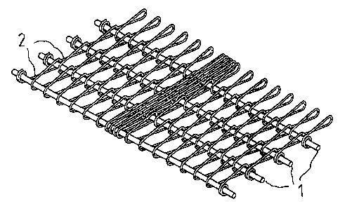
FIG. 1 is a perspective view of a section of a
conveyor belt according to an embodiment of the present
invention.
FIG. 2 is a plan view of the conveyor belt section
illustrated in FIG. 1.
The conveyor belt embodiment shown in FIGS. 1 and 2
has a plurality of transverse rods 1. The transverse rods
1 are connected to each other by means of side links (not
shown), and a plurality of wire spirals 2 are wound
around the transverse rods 1.
Each wire spiral 2 has a flattened helical form and
is wound around two adjacent transverse rods 1 in one
direction. The pitch of each wire spiral _2 is the same
across the width of the conveyor belt except for at a
central part of the conveyor belt where the wire spiral 2
has a much smaller pitch over four complete loops around
the two adjacent transverse rods 1 which are encircled by
the wire spiral 2. More precisely, the pitch in this
central part is approximately equal to twice the diameter
of the wire forming the wire spiral 2. This pitch is the
smallest possible pitch when each wire spiral intermeshes
with the wire spiral 2 on either side thereof, i.e. when
the half-turns of one wire spiral over one transverse rod
intermeshes with the half-turns of one adjacent spiral
over the same transverse rod.
Obviously, the smaller the pitch of a complete loop
of a wire spiral is, the more efficient is that loop in
transferring traction forces between the transverse rods
encircled, i.e. in the longitudinal direction of the
conveyor belt, because the direction of the traction
forces almost coincides with this longitudinal direction.
This efficiency may be further enhanced by reducing the
width of the wire spiral in the longitudinal direction of
the conveyor belt, i.e. reducing the length of the loops.

CA 02295033 1999-12-21
WO 98/58858 PCT/SE98/01202
4
Also, the traction forces when more or less parallel
with the longitudinal direction of the conveyor belt,
have small components in the direction of the transverse
rods tending to displace the turns of the wire spiral
along the transverse rods encircled by that wire spiral
out of their original positions.
It is to be understood that the r_,itch of the wire
spirals may be varied depending upon the needs in each
specific applicatiori and, inter alia, may include several
parts across the width of the conveyor belt each having a
separate, constant pitch, but may also include a conti-
nously varying pitch across the conveyor belt.
Moreover, by varvinq the pitch of the wire spirals
it is possible to provide a desired distribution across
the width of the conveyor belt of the resistance towards
air flow through the conveyor belt, especielly along
laterally curved parts of the conveyor belt path.
A variety of modifications of the conveyor belt
described above are possible within the scope of the
invention as defined in the appended claims.
Thus, where the transverse rods do not need to shift
position in the longitudinal direction of the conveyor
belt, e.g. in the central part of the conveyor belt, the
consecutive loops may be wound in opposite directions
around the transverse rods.
Also, the loops on one side of said first part of
the conveyor belt could increase towards the side edge of
the conveyor belt.

Dessin représentatif
Une figure unique qui représente un dessin illustrant l'invention.
États administratifs

2024-08-01 : Dans le cadre de la transition vers les Brevets de nouvelle génération (BNG), la base de données sur les brevets canadiens (BDBC) contient désormais un Historique d'événement plus détaillé, qui reproduit le Journal des événements de notre nouvelle solution interne.

Veuillez noter que les événements débutant par « Inactive : » se réfèrent à des événements qui ne sont plus utilisés dans notre nouvelle solution interne.

Pour une meilleure compréhension de l'état de la demande ou brevet qui figure sur cette page, la rubrique Mise en garde , et les descriptions de Brevet , Historique d'événement , Taxes périodiques et Historique des paiements devraient être consultées.

Historique d'événement

Description Date
Le délai pour l'annulation est expiré 2015-06-22
Lettre envoyée 2014-06-23
Accordé par délivrance 2007-08-28
Inactive : Page couverture publiée 2007-08-27
Inactive : Taxe finale reçue 2007-06-05
Préoctroi 2007-06-05
Un avis d'acceptation est envoyé 2007-04-18
Lettre envoyée 2007-04-18
Un avis d'acceptation est envoyé 2007-04-18
Inactive : Approuvée aux fins d'acceptation (AFA) 2007-03-16
Modification reçue - modification volontaire 2006-06-09
Inactive : CIB de MCD 2006-03-12
Inactive : Dem. de l'examinateur par.30(2) Règles 2005-12-13
Inactive : CIB attribuée 2005-11-24
Lettre envoyée 2003-05-14
Modification reçue - modification volontaire 2003-05-05
Requête d'examen reçue 2003-04-03
Exigences pour une requête d'examen - jugée conforme 2003-04-03
Toutes les exigences pour l'examen - jugée conforme 2003-04-03
Inactive : Page couverture publiée 2000-02-29
Inactive : CIB en 1re position 2000-02-25
Lettre envoyée 2000-02-10
Inactive : Notice - Entrée phase nat. - Pas de RE 2000-02-10
Demande reçue - PCT 2000-02-04
Demande publiée (accessible au public) 1998-12-30

Historique d'abandonnement

Il n'y a pas d'historique d'abandonnement

Taxes périodiques

Le dernier paiement a été reçu le 2007-05-31

Avis : Si le paiement en totalité n'a pas été reçu au plus tard à la date indiquée, une taxe supplémentaire peut être imposée, soit une des taxes suivantes :

  • taxe de rétablissement ;
  • taxe pour paiement en souffrance ; ou
  • taxe additionnelle pour le renversement d'une péremption réputée.

Les taxes sur les brevets sont ajustées au 1er janvier de chaque année. Les montants ci-dessus sont les montants actuels s'ils sont reçus au plus tard le 31 décembre de l'année en cours.
Veuillez vous référer à la page web des taxes sur les brevets de l'OPIC pour voir tous les montants actuels des taxes.

Titulaires au dossier

Les titulaires actuels et antérieures au dossier sont affichés en ordre alphabétique.

Titulaires actuels au dossier
FRIGOSCANDIA EQUIPMENT AB
Titulaires antérieures au dossier
INGEMAR FRODERBERG
Les propriétaires antérieurs qui ne figurent pas dans la liste des « Propriétaires au dossier » apparaîtront dans d'autres documents au dossier.
Documents

Pour visionner les fichiers sélectionnés, entrer le code reCAPTCHA :


Pour visualiser une image, cliquer sur un lien dans la colonne description du document. Pour télécharger l'image (les images), cliquer l'une ou plusieurs cases à cocher dans la première colonne et ensuite cliquer sur le bouton "Télécharger sélection en format PDF (archive Zip)" ou le bouton "Télécharger sélection (en un fichier PDF fusionné)".

Liste des documents de brevet publiés et non publiés sur la BDBC .

Si vous avez des difficultés à accéder au contenu, veuillez communiquer avec le Centre de services à la clientèle au 1-866-997-1936, ou envoyer un courriel au Centre de service à la clientèle de l'OPIC.


Description du
Document 
Date
(aaaa-mm-jj) 
Nombre de pages   Taille de l'image (Ko) 
Dessin représentatif 2000-02-28 1 24
Abrégé 1999-12-20 1 56
Description 1999-12-20 4 164
Dessins 1999-12-20 1 51
Revendications 1999-12-20 2 48
Revendications 2006-06-08 2 47
Description 2006-06-08 5 182
Dessin représentatif 2007-08-01 1 31
Avis d'entree dans la phase nationale 2000-02-09 1 195
Courtoisie - Certificat d'enregistrement (document(s) connexe(s)) 2000-02-09 1 115
Rappel - requête d'examen 2003-02-24 1 120
Accusé de réception de la requête d'examen 2003-05-13 1 174
Avis du commissaire - Demande jugée acceptable 2007-04-17 1 162
Avis concernant la taxe de maintien 2014-08-03 1 172
PCT 1999-12-20 7 255
Correspondance 2007-06-04 1 38