Note: Descriptions are shown in the official language in which they were submitted.
CA 02295246 2000-O1-11
BACKGROUND OF THE INVENTION
1. Field of the Invention:
The invention relates to an arrangement for dispensing and
applying a binding agent or the like to a surface, and also to a
cleaning device for cleaning the surface to which the binding
agent was applied.
This arrangement is particularly useful for binding an
environmentally-hazardous fluid, such as, for example oil on a
roadway. The az<rangement both prevents soil and ground water
contamination as much as possible and eliminates the hazard which
a film of oil poses to traffic. The arrangement is advantageous
also for binding other substances, especially combustible or
nonvolatile substances that are hazardous to health. The
arrangement is especially advantageous when used by fire
departments, public road maintenance departments, or other
technical assistance organizations. It may also be used in
industrial plants operating with hazardous materials.
-1-
CA 02295246 2000-O1-11
2. The prior Art: -
. It is known to use a mobile arrangement or sprinkler
carriage in an embodiment primarily used in the horticultural
field also for dispensing a binding agent. In this device a
through-like supply container ends in the form of a wedge at its
bottom end. The container hae a row of apertures, through which
the binding agent drops to the ground. The cross section of the
apertures can be changed by means of slides in order~to adjust
the amount of binding agent to be dispensed. A conveying roll is
arranged in the lower area of the Supply container near the
outlet apertures. This arrangement en$ures that the feed o~ the
binding agent is metered and that the binding agent is loosened
in the supply container. This arrangement, however, has not been
successfully used in practice and, therefore, has failed to gain
wide acceptance. For this reason, binding agents in these
applications are typically applied to and distributed over the
surface by hand. The soiled binding agent is subsequently swept
up and disposed of.
A device for removing traces of oil from roads is known from
German Patent DE 43 35 ~~7 C2. This device applies an undiluted
11g111d chemical binding agent to the soiled area via a spray
nozzle, subsequently feeds fresh water, and then aspirates the
resulting mixture into a dirty-water tank.
-2-
STiSO'd 5086 S9~ 9IS 30~ 8 Q~dI~O~ 9b:b1 000-S0-Ndt
l91-q~f 098-b ~O~d 9088 99E 9l9 t~~til 00-90-NVf
CA 02295246 2000-O1-11
Switzerland Patent CH 643314 A 5 describes a sprinkler
device for an oil-binding, flocculent compound. This sprinkler
device has downwardly pointing outlet (or drop) apertures in a
bottom of a hand-held container. A paddle wheel is arranged in
the container above the outlet apertures, and actuated via a
handle. The purpose is to prevent the binding agent from
slacking in the container and to assure uniform dropping from the
container.
German Patent DE 19 25529 U1 shows a device employing a
blower to dispense a binding agent to pick up leaked oil. Bulk-
like binding agent from a supply container is admitted via a
conveyor screw into an air duct between the blower and the
ejection opening. The agent is then carried along in the current
of air. A flexible hose can be connected as an extension to the
outlet opening of the air duct.
SUMMARY OF THE INVENTION
Therefore, the invention provides an arrangement for
dispensing binding agents, which can be handled in a simple and
reliable manner, as well as an advantageous cleaning device with
such an arrangement.
Solutions as defined by the invention are discussed below as
well as advantageous embodiments and further developments of the
invention.
-3-
CA 02295246 2000-O1-11
In the arrangement as defined by the invention, a
distributor device is arranged in the conveying path of the
binding agent downstream of the outlet opening of the supply
container. The distributor device can be advantageously adjusted
in variable ways to adjust the surface area sprinkled by the
distributor device. The binding agent, which is typically in
granulate form,, is subjected to centrifugal force by the movement
of the distributor device around an axis. The rotational motion
guides the binding agent away from the axis and ejects it from
the distributor device onto the surface below. The ability to
adjust the surface area that is sprinkled allows the device to
be adapted to different situations of application, for example
particularly to oil traces on a road having different widths.
According to a preferred embodiment, the distributor device
has a sprinkling plate arrangement with a sprinkling plate
rotating around an axle. Sprinkling plate arrangements are known
for distributing scatterable materials in the agricultural field,
for example for dispensing fertilizers, seeds or soil treatment
agents. Such arrangements are also known for dispensing thawing
salt in winter road service operations. Therefore, dome
constructional details of these known arrangements comprising
sprinkling plates can be employed at least partly in connection
with the preferred embodiment of the invention.
-4-
CA 02295246 2000-O1-11
For example, a winter road service sprinkling device is
known from German Patent DE 40 16 369 C2. A centrifugal disk
rotates about a vertical axle and distributes binding agent over
a large surface area, the binding agent being fed to the disk via
a slanted tube. The ejection range of the centrifugal disk can be
changed with respect to position and alignment by swinging the
tube about a vertical pivot axle.
German Patent DE 32 00 806 A1 describes, among other things,
a device mounted on a vehicle for dispensing solids, admixtures
and chlorides as thawing material in winter road service
operations. A centrifugal disk with a vertical axis of rotation
is provided for distributing the thawing material over a large
surface area.
It was surprisingly found that the sprinkling plate
arrangement is applicable not only for treating the surface with
a low density of the sprinkled material, as is required in the
known cases of application, but advantageously suited also for
dispensing binding agents where a layer substantially covering an
affected surface area, for example a trace of oil, has to be
applied to such surface area in order to pick up the
environmentally hazardous fluid as completely as possible. The
entire contaminated surface area can be covered by dimensioning
the preferably variable cross section of the outlet opening to a
size of at least 10 sq. cm. The sprinkling density can be
CA 02295246 2000-O1-11
changed by adjusting the cross sectional area of the outlet
opening to a lower value versus a maximum cross section.
To sprinkle a typically linear surface area such as, for
example a trace of oil, the arrangement is moved usually in the
direction of the linear trace of oil. Preferably, the sprinkling
density amounts to at least 0.1 liter, preferably at least 0.2
liter binding agent per square meter based on the average of the
surface area to be covered. Parameters such as the rate of
dispensing of the binding agent, the moving speed, the scattering
width and similar factors, determine the sprinkling density.
To sprinkle long-stretching, narrow surface areas, for
example areas having widths under 1.50 meters, and in particular
under lm width, a reversing plate may be provided in the outlet
zone of the sprinkling plate arrangement. The plate catches at
least those portions of the binding agent exiting from the
sprinkling plate arrangement having higher lateral speed
components, and deflects them toward the surface to be sprinkled.
The reversing plate may be removable and/or adjustable. Such a
reversing plate is advantageous, particularly for sprinkling
plates with a substantially vertical axis of rotation.
-6-
CA 02295246 2000-O1-11
The sprinkling plate, in a manner known per ae,
advantageously comprises a substantially planar sprinkling disk,
which is aligned perpendicular to the axis of rotation. A
plurality of ejector blades project substantially perpendicularly
from the sprinkling plate and are at least predominantly radially
directed away from the sprinkling plate. Advantageously,
provision is made for at least four, and in particular, at least
six ejector blades, which are preferably offset against each
other by identical angles. -
zn an advantageous embodiment of a sprinkling plate
arrangement within an arrangement of the invention, ejector
blades distinctly end before reaching the outer edge of the
sprinkling disk. This produces an edge zone in which the binding
agent,is subjected to further uniform distribution by rolling it
over. The spacing of the ends of the ejector blades from the edge
of the sprinkling disk advantageously amounts to at least 15%, in
particular at least 25% of the radius of the sprinkling disk.
The height of the ejector blades above the sprinkling dish
advantageously is greater than 20~, in particular greater than
300 of the radius of the sprinkling disk.
Particularly advantageous is a sprinkling plate arrangement
in which the axis of rotation of the sprinkling dish is inclined
-7-
SW b0'd S086 S9~ 91S 80b ~ Q~d110~ 9b:bt 000-S0-Ndf
l91-q~P 098-b YO d 9088 99E 9l9 Z~~~l 00-90-NVP
CA 02295246 2000-O1-11
against the vertical line, whereby the inclination iS
predominantly, preferably approximately directed in the main
direction of ejection of the arrangement. The main direction of
ejection refers to the mean direction of ejection of material
distributed over an angular range of ejection. The main direction
of ejection is typically the direction in which the arrangement
is moving for sprinkling a line- or strip-like surface area in or
against the direction of motion of the arrangement_ The angle of
inclination of the axis of rotation against the vertical line is
advantageously between 0° and so°, preferably between 5°
and 45°,
in particular between 10° and 30°. In particular, the angle of
inclination may be adjustable.
Tn,particular for a sprinkling plate arrangement with an
axis of rotation inclined against the vertical line, it is
advantageous if the ejector blades are shaped so that the height
of the blades above the sprinkling disk decreases radially
outwardly. In particular, the top edges of the ejector blades
may be disposed on the jacket of a circular cone. The outlet
opening is preferably arranged in the region of the apex in the
range of motion of the top edges of the ejector blades. The area
stretching from the outlet opening extends substantially parallel
with the top edges of the ejector blades sweeping by, in
_ particular horizontally.
_g~
SW ~0'd S086 S9~ 9ZS 30b B Qdd~~O~ 9b:bZ 000-S0-Ndf
l91-qof 098-b fi0~d 9088 99E 9l9 Z4~~1 00-90-NVP
CA 02295246 2000-O1-11
The sprinkling plate arrangement preferably ends below the
outlet opening and does not engage the opening. The rotary axle
of the sprinkling plate arrangement advantageously penetrates the
outlet opening, preferably at a point of penetration offset from
the center of the outlet opening.
Such displacement is advantageous especially in the
direction of the main direction of ejection and preferably
amounts to between loo and 50% of the width of the opening.
Accordingly to an advantageous embodiment, the sum of the
surface areas of the ejector blades amounts to at least 35%,
preferably at least 45% of the surface area of the sprinkling
disk. These percentages favorably influence uniform sprinkling
of the surface to be sprinkled and provide a high sprinkling
density.
To vary the surface area sprinkled with binding agent, it is
possible to change the rotational speed of the sprinkling plate.
Changing the rotational speed of the sprinkling plate is
particularly advantageous, and substantially realizable with
infinite variability or in fine steps, if the distributing device
is equipped with an electric, pneumatic or hydraulic drive. These
types of drive for the distributing device are advantageous also
-9-
CA 02295246 2000-O1-11
in view of the sources of energy typically available for
employing the arrangement, namely aggregates with an electric,
pneumatic or hydraulic output.
Another advantageous embodiment of the invention comprises a
distributing device with a swing arm and uses a principle of
dispensing scatterable material that is known per se. This
principle, however, has not as yet been employed or proposed
heretofore for dispensing binding agents. The swing arm forms a
guide (or feed) chute, which may be designed also in the form of
a tube. The chute or tube performs a swinging motion about a
substantially vertical axis, the agent being fed near the axis.
During this motion the chute ejects the binding agent
centrifugally. The width of sprinkling of the binding agent may
be varied by adjusting the deflection of the swing arm and/or by
varying the swing rate of the swing arm. The statements made
above with respect to the sprinkling plate arrangement apply
correspondingly to the drive of the swing arm.
According to another advantageous arrangement, the
distributing device is provided with a blade wheel revolving
around a substantially vertical axis. The blade wheel is fed with
the binding agent preferably in the vicinity of the apex. For
distributing the binding agent transversely to the main direction
of ejection, a baffle plate arrangement is useful.
-10-
CA 02295246 2000-O1-11
The arrangement may be designed in the form of a mobile unit,
which, in addition to the preferred types of drive specified
above, may also comprise a coupling of the drive of the
distributing device to the driving motion via a mechanical
gearing. According to another advantageous embodiment, the
arrangement is designed in the form of an attachment to a self-
driving vehicle.
The supply device and/or the feed lines for feeding the
binding agent to the outlet opening may advantageously contain
devices preventing the binding agent from freezing, or getting
clogged, or for eliminating such freezing or clogging. Such
devices may have the form of agitating or stirring devices.
A cleaning device as defined by the invention, with a
dispensing arrangement of the type described above, is designed
as a mobile device, In addition to the dispensing arrangement,
the device comprises at least one pick-up device, which picks up
contaminated binding agent from the sprinkled surface. The
dispensing arrangement, which is arranged in front of the pick-up
device in the driving direction, sprinkles the contaminated or
soiled surface with binding agent, which binds the contaminating
material. The trailing pick-up device picks up the contaminated
binding agent and collects it in a container. The pick-up device
particularly may comprise a sweeping device and/or a suction
device.
-11-
CA 02295246 2000-O1-11
For driving the cleaning device, both the dispensing
arrangement and the pick-up device may be designed according to
one embodiment in the form of attachments mounted on a self-
driving vehicle, for example a fire department vehicle or road
service utility vehicle. Each attaching device may be supported
solely by the vehicle, without their owr_ ground support, or they
may have their own non-driven chassis, in particular in the form
of a towed trailer vehicle for the pick-up device. Preferably,
the dispensing arrangement is mounted on the front side of the
vehicle and the pick-up device on its rear side.
According to another embodiment, one of the devices may be
self-driving and the other may be designed as an attachment
device mounted on the self-driving device.
The sprinkling arrangement, which is located in front of the
pick-up device dewed in the driving direction, preferably points
with its main direction of ejection in the driving direction,
i.e. it sprinkles ahead as it moves.
A mechanical re-distributing arrangement may also be
provided between the pick-up device and the dispensing (or
sprinkling) arrangement. This re-distributing arrangement brings
the binding agent applied to the contaminated surface into
intimate contact with the contaminate by re-distributing it and
turning it over on the soiled surface in the way of manual
-12-
CA 02295246 2000-O1-11
sweeping up. In this way, superior bonding of the contaminant to
the binding agent is assured.
Essentially any known drive can be used as a drive for the
dispensing arrangement and/or the pick-up device. For attaching
devices it is preferred to employ drives using power sources
available on the carrier vehicle, in particular electrical,
pneumatic or hydraulic drives. With devices mounted on a chassis,
it is possible also to make provision for a mechanical drive via
the rotation of the wheels.
As additional equipment for the cleaning device, and in
particular in connection with a pick-up device comprising a
suction device, it is possible also to make provision for an
auxiliary device, for example in the form of a stream jet device
or a high-pressure cleaner for detaching and removing the soiled
binding agent from the sprinkled surface. The auxiliary device
is preferably arranged with a small spacing from the pick-up
device.
A suitable binding agent is known, for example from German
Patent DE 18 11 131 B2.
--13-
CA 02295246 2000-O1-11
BRIEF DESCRIPTION OF THE DRAWINGS:
Other objects and features of the present invention will
become apparent from the following detailed description
considered in connection with the drawings which disclose
preferred embodiments of the present invention. It should be
understood, however, that the drawings are designed for the
purpose of illustration only and not as a definition of the
limits of the invention.
In the drawings, wherein similar reference characters denote
similar elements throughout the several views:
FIG. 1 shows an arrangement with the sprinkling plate and
distributing device on the dispensing side.
FIG. 2 is a top view of the plane of the sprinkling plate in
FIG. 1.
FIG. 3 shows a preferred design with the sprinkling plate.
FIG. 4 is a top view of the sprinkling plate arrangement
according to FIG. 3.
FIG. 5 shows an embodiment with a blade wheel.
-14-
CA 02295246 2000-O1-11
FIG. 6 is a side view of FIG. 5; and
FIG. 7 shows a cleaning device with an arrangement for
dispensing binding agent.
DETAILED DESCRIPTION OF PREFERRED EMBODIMENTS
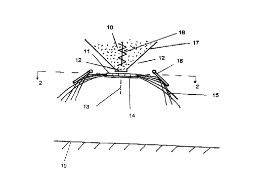
FIG. 1 shows a horizontal view from the dispensing side of
an advantageous embodiment of the arrangement with a sprinkling
plate as the distributing device. A sprinkling plate 14 is
designed in the form of a substantially planar and horizontally
aligned disk, which supports a multitude of ejection blades. The
sprinkling plate is driven above or below by a suitable motor
drive (not shown) and revolves around a substantially vertical
rotary axis 13. FIG. 2 shows a top view of a cross section taken
through line 2-2 of FIG. 1 of the sprinkling plate of the
arrangement according to FIG. 1.
A supply of granular binding agent is present in a supply
container 17. The binding agent drops onto the rotating plate
through an outlet opening 12 located above the sprinkling plate,
with substantially uniform metering of the amount being
dispensed. The cross section of the outlet opening can be
narrowed down versus the maximum width of the opening by means of
a slide not shown in the drawing. An agitating device 18 located
-15-
CA 02295246 2000-O1-11
in the supply container 17 prevents freezing of the binding agent
15 in the supply container.
The binding agent dropping onto the sprinkling plate through
the outlet opening 12 is carried along by the ejection blades and
carried outwardly by centrifugal forces. It is then ejected onto
the surface 19 across the edge of the disk within a sprinkling
angle 20. The average initial ejection speed and thus the
distance over which the binding material is thrown, are
substantially determined by the geometry of the sprinkling plate
with the ejection blades, and by the rotational speed of the
sprinkling plate, and are adjustable especially through the
adjustment of the rotational speed.
For long-stretching surface areas with a small width, no
greater ejection distances are needed and also are not desired
because of the higher consumption of binding agent if the binding
agent is thrown over a great distance. Especially when covering
such areas, reversing (or deflecting) baffle plates 16 maybe
provided for. limiting the ejection distance sideways. Such
baffle plates deflect at least the components of the binding
agent sprinkled with a higher ejection speed and, therefore,
deflect such components in the direction of the surface 19 with a
flatter trajectory. For the purpose of varying the limitation of
the ejection distance, the deflecting baffle plates may be
adjustable particularly with respect to their lower edging.
-16-
CA 02295246 2000-O1-11
Also, the deflecting baffle plates may be closed in the form of a
U-shaped or semi-circularly shaped ring.
It is particularly important in connection with the preferred
embodiment sketched in the side view according to FIG. 3 that the
direction of the axis of rotation 13 of the sprinkling plate
arrangement is inclined against the vertical line 31 by an angle
30 of about 20 degrees in the case of the present exemplified
embodiment. The plane sprinkling disk 32 of the sprinkling plate
arrangement is aligned perpendicular to the axis of rotation.
The angle of inclination may be adjusted, for example, by a hinge
26 connecting support plate 33 and sprinkling plate carrier 28.
The ejection blades 11, which projects from the plane of the
sprinkling disk 32, show a blade height above the sprinkling disk
32 which radially decreases outwardly. In this way, the blades
reach outwardly only up to a radius 38, which is clearly smaller
than the radius 37 of the sprinkling disk 32, as illustrated by
the top view of the sprinkling plate arrangement sketched in FIG.
4. As shown in FIG. 4, blades 26 generally radiate outwardly
from a single point offset from the center 39 of the outlet
opening 12.
Due to omission of the surfaces of the blades in the edge
zone 27, the binding agent centrifugally accelerated by being
carried along by the blades is capable of rolling over, so that
-17-
CA 02295246 2000-O1-11
further improvement of the uniformity of the ejection pattern can
be achieved.
In the embodiment of FIG. 3, the sprinkling plate
arrangement is supported by a sprinkling plate carrier 28, which
has a driving arrangement, for example an electric motor 29
arranged on its underside. The electric motor is connected with
the sprinkling plate arrangement via a driving shaft. The
sprinkling plate arrangement 28 is connected with a support plate
33, for mounting the arrangement, for example on a vehicle.
Furthermore, a supply container carrier 25 for supporting and
holding the supply container 17 is connected with the support
plate 33.
The outlet opening 12 is arranged in the vicinity of the
apex of movement of the top edges of the ejection blades 26.
The top edges of the ejection blades substantially extend in
this area parallel with the area stretching from the outlet
opening, preferably in a substantially horizontal way.
The axis of rotation advantageously penetrates the outlet
opening. The position 35 of the axis of rotation is preferably
offset in the main direction of ejection against the center 39 of
the outlet opening 12 by a distance 34, as shown in FIG. 3. The
displacement distance 34 preferably amounts to between l0a and
500 of the opening width 36 of the outlet opening.
-18-
CA 02295246 2000-O1-11
'Viewed in the main direction-of ejection, FIG. 5 shows a
distributing device with a blade wheel 9~6 revolving around a
horizontal axis of rotation 47. Between two side plates 45, the
blade (or bucket) wheel has a multitude of driving blades or
buckets predominantly extending in the radial direction. The
blade or bucket wheel is Connected via a driving shaft 48 with a
dx-iving arrangement such as, for example a laterally arranged
electric motor 29. FIG. 6 shows a s~,de view of the arrangement
according to FIG. 5, in which the motor and one side~plate are
omitted.
From the supply container, binding agent is transported onto
the blade wheel via the outlet opening 12 positioned in the
region of the apex of the blade wheel, then carried along by the
blades, 49, and subsequently thrown in the direction of ejection
onto the surface to be sprinkled. Fox' achieving a stronger
component of lateral ejection far portions of the ejected binding
agent, the driving blades and/or the side plates may be provided
with a curvature. Alternatively, or in addi~.ion, deflecting
plates or the like may be provided within the area of ejection.
FIG. 7 shows.an advantageous cleaning device, where an
arrangement 53 for dispensing a binding agent 54 and sprinkling
it over a contaminated or soiled surface 55 is secured on tl~e
front side of a self-driving vehicle 52. The arrangement 53
-19-
SZi~O'd 5086 S9~ 91S 308 '8 Qbd110~ 9b:bZ 000-S0-Ndt
l91-q~f 0~8-b ZO d 9088 99fi 9l~ Z~~YI 00-~0-NVf
CA 02295246 2000-O1-11
throws binding agent onto the surface 55 in the driving direction
58 of the vehicle 52. The arrangement 53 is driven by on-board
power equipment of the vehicle 52.
A collection device 56 for receiving soiled (or
contaminated) binding agent is designed in the form of a mobile
trailer unit, which is towed behind the vehicle 52 by the
vehicle. On its underside facing the surface 55, the collecting
device 56 has a sweeping device 59, which picks up soiled binding
agent lying on the surface 55 and conveys the binding agent into
a collection container 57 of the collection (receiving) device.
Again, the drive of the sweeping device 59 may be fed via on-
board supply equipment of the vehicle 52. Alternatively the
device may be driven by mechanically coupling it to the rotation
of the wheels of the trailer.
The design of the cleaning device may conceivably comprise a
great number of possibilities for combining the individual
components.
The features described above and in the claims can be
advantageously realized both individually and in different
combinations. The invention is not limited to the exemplified
embodiments described above, but can be modified in many ways
within the scope of the skills of the expert in this field. For
-20-
CA 02295246 2000-O1-11
example, the drive may be designed in various ways as will be
apparent to an expert in this field.
Accordingly, while several embodiments of the present
invention have been shown and described, it is to be understood
that many changes and modifications may be made thereunto without
departing from the spirit and scope of the invention as defined
in the appended claims.
--21-