Language selection

Search

Patent 2295258 Summary

Third-party information liability

Some of the information on this Web page has been provided by external sources. The Government of Canada is not responsible for the accuracy, reliability or currency of the information supplied by external sources. Users wishing to rely upon this information should consult directly with the source of the information. Content provided by external sources is not subject to official languages, privacy and accessibility requirements.

Claims and Abstract availability

Any discrepancies in the text and image of the Claims and Abstract are due to differing posting times. Text of the Claims and Abstract are posted:

  • At the time the application is open to public inspection;
  • At the time of issue of the patent (grant).
(12) Patent: (11) CA 2295258
(54) English Title: TANG BREAK-OFF TOOL
(54) French Title: OUTIL PERMETTANT D'ENLEVER LES DEBRIS D'UN PIVOT ET/OU TENON
Status: Term Expired - Post Grant Beyond Limit
Bibliographic Data
(51) International Patent Classification (IPC):
  • B25B 27/00 (2006.01)
  • B25B 27/14 (2006.01)
  • F16B 37/12 (2006.01)
(72) Inventors :
  • HONDO, FUSAHIDE (Japan)
(73) Owners :
  • NIPPON SPREW CO., LTD.
(71) Applicants :
  • NIPPON SPREW CO., LTD. (Japan)
(74) Agent: MARKS & CLERK
(74) Associate agent:
(45) Issued: 2009-09-08
(22) Filed Date: 2000-01-11
(41) Open to Public Inspection: 2001-02-20
Examination requested: 2003-12-22
Availability of licence: N/A
Dedicated to the Public: N/A
(25) Language of filing: English

Patent Cooperation Treaty (PCT): No

(30) Application Priority Data:
Application No. Country/Territory Date
11-234816 (Japan) 1999-08-20

Abstracts

English Abstract

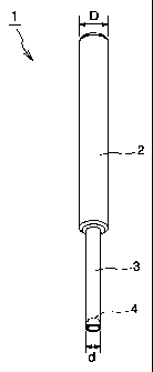
The present invention provides a tang break-off tool which makes it possible to break off the tang after inserting the spiral coil insert with the tang into the taphole of the work, and further, to easily and with certainty remove the broken tang. The tool has a grip section 2 and an operating section 3, and has a permanent magnet 4 provided at the leading end of the operating section 3.


French Abstract

Le présent instrument consiste en un outil permettant d'enlever les débris d'un tenon; il permet de briser le tenon une fois que la pièce rapportée en spirale a été insérée au moyen du tenon dans le trou du taraud de l'ouvrage et, plus en profondeur, afin d'enlever facilement de façon nette les débris du tenon. L'outil est doté d'un manche (2) et d'une partie opérationnelle (3); il possède également un aimant (4) situé à l'embout avant de la section opérationnelle (3).

Claims

Note: Claims are shown in the official language in which they were submitted.

The embodiments of the invention in which an exclusive property or privilege
is
claimed are defined as follows:
1. A tang break-off tool having a grip section and a working section, said
working
section having a leading end adapted for contacting the tang of an insert,
said grip section
presenting a surface for gripping of the tool by the user, said tool further
having a
permanent magnet secured in a recess formed in the leading end of said working
section
such that the permanent magnet does not project from said leading end.
-7-

Description

Note: Descriptions are shown in the official language in which they were submitted.


CA 02295258 2000-01-11
TITLE OF THE INVENTION
TANG BREAK-OFF TOOL
BACKGROUND OF THE INVENTION
Field of the Invention
The present invention relates to a tang break-off tool which permits
breaking off a tang after inserting a spiral coil insert with a tang into a
taphole of a work, and the further removal of the tang as broken off.
Description of the Related Art
When a weak female screw makes it impossible to obtain a high
tightening force while directly tapping into a work comprising a light metal
such as aluminum, plastics, wood or cast iron, it is the conventional practice
to use a tanged spiral coil insert for the purpose of ensuring a high reliable
screw tightening. Fig. 5 illustrates an example of the tanged spiral coil
insert.
As shown in Fig. 5, a spiral coil insert with a tang 10 is usually
manufactured by winding a high strength special steel wire having a
rhombic cross-section into.a spring-shaped cylinder. It is screwed into a
taphole 101 formed in a work 100 by means of an inserting tool, as shown in
fig. 6, and fixed therein. Thereafter, a bolt 20 or the like is screw-engaged
with this spiral coil insert 10 as a female screw. By using the spiral coil
insert 10 as described above, it is possible to obtain a high screw tightening
force, to repeatedly insert the bolt 20, and to remove the same.
Because the tanged spiral coil insert 10 is screwed into the taphole
-t-

CA 02295258 2000-01-11
101 by the use of the insertion tool as described above, a stopper piece 11,
folded in the radial direction of the coil, known as a tang engaged to the
insertion tool is provided at the coil free end as shown in fig. 5. After the
coil inse"rt 10 is secured in the taphole 101 of the work 100, this tang must
be removed. For this purpose, a notch 12 is formed on the outer side
surface of the coil at a first coil portion to be connected to the coil free
end on
which the tang 11 is formed.
From the tanged spiral coil insert 10 as described above, the tang 11
is broken off after attachment to the work 100, and the broken tang 11 must
be collected. Particularly when the taphole 101 of the work 100 takes the
form of a blind hole, this operation is very difficult. If collection of the
separated tang 11 fails, the tang 11 may cause electrical or mechanical
failure. It is therefore necessary to remove the separated tang without fail.
When the taphole 101 of the work 100 is formed into a blind hole, it is
the present practice to remove the separated tang 11 by, for example, tilting
the work 100. This practice is not effective however when the work is large
in size. When the tanged spiral coil insert 10 is large in size, the separated
tang can be removed by the use of a pincette or the like. However, in the
case of a small-diameter tanged spiral coil insert 10, this practice is
sometimes not applicable. There is therefore a demand for a method of
certain and easy removal of the separated tang.
As a result of extensive studies and experiments carried out to solve
the above-mentioned problems, the present inventor obtained the following
findings. Even when a tanged spiral coil insert 10 is prepared through
many cold working steps by the use of 18-8 stainless steel (SUS304) wire
-2-

CA 02295258 2007-11-22
usually considered to be a non-magnetic material, the prepared tanged
spiral coil insert 10 exhibits properties of magnetic material. The inventor
found, in view of this fact, the possibility of being able to remove a snapped
tang by attracting it with a magnet.
The present invention is based on such novel findings obtained by the
inventor.
SUMMARY OF THE INVENTION
The present invention has therefore an object to provide a tang
break-off tool which, after attaching a spiral coil insert with a tang to a
taphole of a work, makes it possible to break off the tang, and further, to
facilitate the easy and certain removal of the broken tang.
The aforementioned object is achieved by the use of the tang break-off
tool of the invention. In summary, the invention relates to a tang break-off
tool having a grip section, an operating section and a permanent magnet
provided on the leading end of the operating section.
According to an embodiment of the invention, the above-mentioned
permanent magnet is secured in a recess formed on the leading end of the
operating section. The permanent magnet should preferably not project
from the leading end of the operating section.
-3-

CA 02295258 2007-11-22
According to an aspect of the present invention there is provided a tang break-
off
too] having a grip section and a working section, said working section having
a leading
end adapted for contacting the tang of an insert, said grip section presenting
a surface for
gripping of the tool by the user, said tool further having a permanent magnet
secured in a
recess formed in the leading end of said working section such that the
permanent magnet
does not project from said leading end.
BRIEF DESCRIPTION OF THE DRAWINGS
Fig. I is a perspective view illustrating an embodiment of the tang break-off
tool
of the present invention;
Fig. 2 is an enlarged sectional view illustrating the configuration of
-3a-

CA 02295258 2000-01-11
the leading end of the tang break-off tool of the invention;
Fig. 3 illustrates the manner of use of the tang break-off tool of the
invention;
Fig. 4 illustrates the manner of use of the tang break-off tool of the
invention;
Fig. 5 is a perspective view of a tang spiral coil insert; and
Fig. 6 illustrates the tang spiral coil insert being attached to a work.
DESCRIPTION OF THE PREFERRED EMBODIMENTS
The tang break-off tool of the present invention will now be described
in further detail with reference to the drawings.
Fig.1 illustrates an embodiment of the tang break-off tool of the
invention. According to this embodiment, the tang break-off tool 1 has a
grip section 2 and an operating section 3. The grip section 2 has a size
which permits easy grip by an operator: in this embodiment, the grip section
2 has a diameter (D) of 10 mm and a length of 8 cm, but is not limited. The
geometry of the operating section - 3, varying with the size of the tanged
spiral coil insert 10 used, comprises a diameter of 4 mm and a length of 3.5
cm in this embodiment, so that it serves as a tool for a tanged spiral coil
insert 10 having an inside diameter of 5 mm and a length of about 1 cm. In
this embodiment, the grip section 2 and the operating section 3 are
prepared as one body from a steel material such as S45C, but it may be
made of any arbitrary material.
According to the invention, as shown in Fig. 2, a permanent magnet 4
is arranged on the leading end of the operating section 3. In this
-4-

CA 02295258 2000-01-11
embodiment, a recess 5 is formed at the leading end of the operating section
3, and the permanent magnet 4 is secured in the recess 5 with an adhesive
or the like. It is preferable that the permanent magnet 4 does not project
from the leading end of the operating section 3: iin the present embodiment,
it is located at a position about 0.5 mm in depth (h2). In this configuration,
upon breaking off a tang 11 with the tool, it is possible to prevent the
permanent magnet 4 from coming into contact with the tang 11 and causing
a damage thereto.
The strength of the magnet 4 is such that the tang snapped off from
the tanged spiral coil insert 10 can be attracted. In this embodiment, a
magnet having a diameter (dl) of 3 mm and a height (hl) of 4 mm and
having different magnet poles on both surfaces as shown in Fig. 2 is used,
but the geometry of the magnet 4 is not limited to this.
A manner of use of the tool 1 having the above-mentioned
configuration of the invention will now be described with reference to Fig. 3.
As shown in Fig. 3(A), when the tanged spiral coil insert 10 is
attached to the work 100, the tool 1 of the invention is inserted into the
tanged spiral coil insert 10, and brings the leading end of the operating
section 3 into contact with the tang 11 of the tanged spiral coil insert 10.
Then, the tang 11 is broken off at a notch 12 (Fig. 5) by hitting the top end
of
the grip section 2 with a tool such as a hammer. The tang 11 broken off as
described above is illustrated in Fig. 3(B). It is needless to mention that
the tanged spiral coil insert 10 is prepared from a material having
properties of a magnetic material as a result of cold working, such as a 18-8
stainless steel wire, or an arbitrary material believed to be magnetic
-5-

CA 02295258 2000-01-11
material.
After breaking off the tang 11, the snapped tang 11 is attracted by the
magnet 4 of he operating section 3 at the leading end of the tool, as shown in
Fig. 3(C), by causing the tool 1 to descend. In this state, the tang 11 can be
taken out as shown in Fig. 4 by pulling up the tool 1.
As described above, the tang break-off tool of the present invention
has a grip section and an operating section and has a permanent magnet
provided at the leading end of the operating section. It is therefore
possible to break off the tang after inserting the tanged spiral coil insert
into the taphole of the work, and further, to easily and with certainty
remove the tang as broken off.
-6-

Representative Drawing
A single figure which represents the drawing illustrating the invention.
Administrative Status

2024-08-01:As part of the Next Generation Patents (NGP) transition, the Canadian Patents Database (CPD) now contains a more detailed Event History, which replicates the Event Log of our new back-office solution.

Please note that "Inactive:" events refers to events no longer in use in our new back-office solution.

For a clearer understanding of the status of the application/patent presented on this page, the site Disclaimer , as well as the definitions for Patent , Event History , Maintenance Fee  and Payment History  should be consulted.

Event History

Description Date
Inactive: Expired (new Act pat) 2020-01-13
Common Representative Appointed 2019-10-30
Grant by Issuance 2009-09-08
Inactive: Cover page published 2009-09-07
Inactive: Final fee received 2009-06-29
Pre-grant 2009-06-29
Notice of Allowance is Issued 2009-04-03
Letter Sent 2009-04-03
Notice of Allowance is Issued 2009-04-03
Inactive: Approved for allowance (AFA) 2009-01-31
Amendment Received - Voluntary Amendment 2008-10-24
Inactive: S.30(2) Rules - Examiner requisition 2008-04-24
Amendment Received - Voluntary Amendment 2007-11-22
Inactive: S.30(2) Rules - Examiner requisition 2007-05-22
Inactive: IPC from MCD 2006-03-12
Amendment Received - Voluntary Amendment 2004-06-04
Letter Sent 2004-01-20
Request for Examination Requirements Determined Compliant 2003-12-22
All Requirements for Examination Determined Compliant 2003-12-22
Request for Examination Received 2003-12-22
Inactive: Entity size changed 2002-01-07
Application Published (Open to Public Inspection) 2001-02-20
Inactive: Cover page published 2001-02-19
Letter Sent 2000-07-18
Inactive: Single transfer 2000-06-09
Inactive: First IPC assigned 2000-03-03
Inactive: IPC assigned 2000-03-03
Inactive: Courtesy letter - Evidence 2000-02-15
Inactive: Filing certificate - No RFE (English) 2000-02-14
Application Received - Regular National 2000-02-08

Abandonment History

There is no abandonment history.

Maintenance Fee

The last payment was received on 2008-12-03

Note : If the full payment has not been received on or before the date indicated, a further fee may be required which may be one of the following

  • the reinstatement fee;
  • the late payment fee; or
  • additional fee to reverse deemed expiry.

Patent fees are adjusted on the 1st of January every year. The amounts above are the current amounts if received by December 31 of the current year.
Please refer to the CIPO Patent Fees web page to see all current fee amounts.

Owners on Record

Note: Records showing the ownership history in alphabetical order.

Current Owners on Record
NIPPON SPREW CO., LTD.
Past Owners on Record
FUSAHIDE HONDO
Past Owners that do not appear in the "Owners on Record" listing will appear in other documentation within the application.
Documents

To view selected files, please enter reCAPTCHA code :


To view images, click a link in the Document Description column. To download the documents, select one or more checkboxes in the first column and then click the "Download Selected in PDF format (Zip Archive)" or the "Download Selected as Single PDF" button.

List of published and non-published patent-specific documents on the CPD .

If you have any difficulty accessing content, you can call the Client Service Centre at 1-866-997-1936 or send them an e-mail at CIPO Client Service Centre.


Document
Description 
Date
(yyyy-mm-dd) 
Number of pages   Size of Image (KB) 
Representative drawing 2001-02-05 1 2
Abstract 2000-01-10 1 13
Description 2000-01-10 6 232
Drawings 2000-01-10 6 60
Claims 2000-01-10 1 14
Description 2007-11-21 7 241
Claims 2007-11-21 1 14
Drawings 2008-10-23 6 58
Representative drawing 2009-08-10 1 2
Filing Certificate (English) 2000-02-13 1 164
Courtesy - Certificate of registration (related document(s)) 2000-07-17 1 114
Reminder of maintenance fee due 2001-09-11 1 116
Acknowledgement of Request for Examination 2004-01-19 1 174
Commissioner's Notice - Application Found Allowable 2009-04-02 1 163
Correspondence 2000-02-13 1 14
Fees 2007-11-08 1 42
Correspondence 2009-06-28 1 31