Sélection de la langue

Search

Sommaire du brevet 2295258 

Énoncé de désistement de responsabilité concernant l'information provenant de tiers

Une partie des informations de ce site Web a été fournie par des sources externes. Le gouvernement du Canada n'assume aucune responsabilité concernant la précision, l'actualité ou la fiabilité des informations fournies par les sources externes. Les utilisateurs qui désirent employer cette information devraient consulter directement la source des informations. Le contenu fourni par les sources externes n'est pas assujetti aux exigences sur les langues officielles, la protection des renseignements personnels et l'accessibilité.

Disponibilité de l'Abrégé et des Revendications

L'apparition de différences dans le texte et l'image des Revendications et de l'Abrégé dépend du moment auquel le document est publié. Les textes des Revendications et de l'Abrégé sont affichés :

  • lorsque la demande peut être examinée par le public;
  • lorsque le brevet est émis (délivrance).
(12) Brevet: (11) CA 2295258
(54) Titre français: OUTIL PERMETTANT D'ENLEVER LES DEBRIS D'UN PIVOT ET/OU TENON
(54) Titre anglais: TANG BREAK-OFF TOOL
Statut: Durée expirée - au-delà du délai suivant l'octroi
Données bibliographiques
(51) Classification internationale des brevets (CIB):
  • B25B 27/00 (2006.01)
  • B25B 27/14 (2006.01)
  • F16B 37/12 (2006.01)
(72) Inventeurs :
  • HONDO, FUSAHIDE (Japon)
(73) Titulaires :
  • NIPPON SPREW CO., LTD.
(71) Demandeurs :
  • NIPPON SPREW CO., LTD. (Japon)
(74) Agent: MARKS & CLERK
(74) Co-agent:
(45) Délivré: 2009-09-08
(22) Date de dépôt: 2000-01-11
(41) Mise à la disponibilité du public: 2001-02-20
Requête d'examen: 2003-12-22
Licence disponible: S.O.
Cédé au domaine public: S.O.
(25) Langue des documents déposés: Anglais

Traité de coopération en matière de brevets (PCT): Non

(30) Données de priorité de la demande:
Numéro de la demande Pays / territoire Date
11-234816 (Japon) 1999-08-20

Abrégés

Abrégé français

Le présent instrument consiste en un outil permettant d'enlever les débris d'un tenon; il permet de briser le tenon une fois que la pièce rapportée en spirale a été insérée au moyen du tenon dans le trou du taraud de l'ouvrage et, plus en profondeur, afin d'enlever facilement de façon nette les débris du tenon. L'outil est doté d'un manche (2) et d'une partie opérationnelle (3); il possède également un aimant (4) situé à l'embout avant de la section opérationnelle (3).


Abrégé anglais

The present invention provides a tang break-off tool which makes it possible to break off the tang after inserting the spiral coil insert with the tang into the taphole of the work, and further, to easily and with certainty remove the broken tang. The tool has a grip section 2 and an operating section 3, and has a permanent magnet 4 provided at the leading end of the operating section 3.

Revendications

Note : Les revendications sont présentées dans la langue officielle dans laquelle elles ont été soumises.


The embodiments of the invention in which an exclusive property or privilege
is
claimed are defined as follows:
1. A tang break-off tool having a grip section and a working section, said
working
section having a leading end adapted for contacting the tang of an insert,
said grip section
presenting a surface for gripping of the tool by the user, said tool further
having a
permanent magnet secured in a recess formed in the leading end of said working
section
such that the permanent magnet does not project from said leading end.
-7-

Description

Note : Les descriptions sont présentées dans la langue officielle dans laquelle elles ont été soumises.

CA 02295258 2000-01-11
TITLE OF THE INVENTION
TANG BREAK-OFF TOOL
BACKGROUND OF THE INVENTION
Field of the Invention
The present invention relates to a tang break-off tool which permits
breaking off a tang after inserting a spiral coil insert with a tang into a
taphole of a work, and the further removal of the tang as broken off.
Description of the Related Art
When a weak female screw makes it impossible to obtain a high
tightening force while directly tapping into a work comprising a light metal
such as aluminum, plastics, wood or cast iron, it is the conventional practice
to use a tanged spiral coil insert for the purpose of ensuring a high reliable
screw tightening. Fig. 5 illustrates an example of the tanged spiral coil
insert.
As shown in Fig. 5, a spiral coil insert with a tang 10 is usually
manufactured by winding a high strength special steel wire having a
rhombic cross-section into.a spring-shaped cylinder. It is screwed into a
taphole 101 formed in a work 100 by means of an inserting tool, as shown in
fig. 6, and fixed therein. Thereafter, a bolt 20 or the like is screw-engaged
with this spiral coil insert 10 as a female screw. By using the spiral coil
insert 10 as described above, it is possible to obtain a high screw tightening
force, to repeatedly insert the bolt 20, and to remove the same.
Because the tanged spiral coil insert 10 is screwed into the taphole
-t-

CA 02295258 2000-01-11
101 by the use of the insertion tool as described above, a stopper piece 11,
folded in the radial direction of the coil, known as a tang engaged to the
insertion tool is provided at the coil free end as shown in fig. 5. After the
coil inse"rt 10 is secured in the taphole 101 of the work 100, this tang must
be removed. For this purpose, a notch 12 is formed on the outer side
surface of the coil at a first coil portion to be connected to the coil free
end on
which the tang 11 is formed.
From the tanged spiral coil insert 10 as described above, the tang 11
is broken off after attachment to the work 100, and the broken tang 11 must
be collected. Particularly when the taphole 101 of the work 100 takes the
form of a blind hole, this operation is very difficult. If collection of the
separated tang 11 fails, the tang 11 may cause electrical or mechanical
failure. It is therefore necessary to remove the separated tang without fail.
When the taphole 101 of the work 100 is formed into a blind hole, it is
the present practice to remove the separated tang 11 by, for example, tilting
the work 100. This practice is not effective however when the work is large
in size. When the tanged spiral coil insert 10 is large in size, the separated
tang can be removed by the use of a pincette or the like. However, in the
case of a small-diameter tanged spiral coil insert 10, this practice is
sometimes not applicable. There is therefore a demand for a method of
certain and easy removal of the separated tang.
As a result of extensive studies and experiments carried out to solve
the above-mentioned problems, the present inventor obtained the following
findings. Even when a tanged spiral coil insert 10 is prepared through
many cold working steps by the use of 18-8 stainless steel (SUS304) wire
-2-

CA 02295258 2007-11-22
usually considered to be a non-magnetic material, the prepared tanged
spiral coil insert 10 exhibits properties of magnetic material. The inventor
found, in view of this fact, the possibility of being able to remove a snapped
tang by attracting it with a magnet.
The present invention is based on such novel findings obtained by the
inventor.
SUMMARY OF THE INVENTION
The present invention has therefore an object to provide a tang
break-off tool which, after attaching a spiral coil insert with a tang to a
taphole of a work, makes it possible to break off the tang, and further, to
facilitate the easy and certain removal of the broken tang.
The aforementioned object is achieved by the use of the tang break-off
tool of the invention. In summary, the invention relates to a tang break-off
tool having a grip section, an operating section and a permanent magnet
provided on the leading end of the operating section.
According to an embodiment of the invention, the above-mentioned
permanent magnet is secured in a recess formed on the leading end of the
operating section. The permanent magnet should preferably not project
from the leading end of the operating section.
-3-

CA 02295258 2007-11-22
According to an aspect of the present invention there is provided a tang break-
off
too] having a grip section and a working section, said working section having
a leading
end adapted for contacting the tang of an insert, said grip section presenting
a surface for
gripping of the tool by the user, said tool further having a permanent magnet
secured in a
recess formed in the leading end of said working section such that the
permanent magnet
does not project from said leading end.
BRIEF DESCRIPTION OF THE DRAWINGS
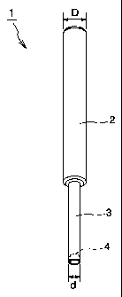
Fig. I is a perspective view illustrating an embodiment of the tang break-off
tool
of the present invention;
Fig. 2 is an enlarged sectional view illustrating the configuration of
-3a-

CA 02295258 2000-01-11
the leading end of the tang break-off tool of the invention;
Fig. 3 illustrates the manner of use of the tang break-off tool of the
invention;
Fig. 4 illustrates the manner of use of the tang break-off tool of the
invention;
Fig. 5 is a perspective view of a tang spiral coil insert; and
Fig. 6 illustrates the tang spiral coil insert being attached to a work.
DESCRIPTION OF THE PREFERRED EMBODIMENTS
The tang break-off tool of the present invention will now be described
in further detail with reference to the drawings.
Fig.1 illustrates an embodiment of the tang break-off tool of the
invention. According to this embodiment, the tang break-off tool 1 has a
grip section 2 and an operating section 3. The grip section 2 has a size
which permits easy grip by an operator: in this embodiment, the grip section
2 has a diameter (D) of 10 mm and a length of 8 cm, but is not limited. The
geometry of the operating section - 3, varying with the size of the tanged
spiral coil insert 10 used, comprises a diameter of 4 mm and a length of 3.5
cm in this embodiment, so that it serves as a tool for a tanged spiral coil
insert 10 having an inside diameter of 5 mm and a length of about 1 cm. In
this embodiment, the grip section 2 and the operating section 3 are
prepared as one body from a steel material such as S45C, but it may be
made of any arbitrary material.
According to the invention, as shown in Fig. 2, a permanent magnet 4
is arranged on the leading end of the operating section 3. In this
-4-

CA 02295258 2000-01-11
embodiment, a recess 5 is formed at the leading end of the operating section
3, and the permanent magnet 4 is secured in the recess 5 with an adhesive
or the like. It is preferable that the permanent magnet 4 does not project
from the leading end of the operating section 3: iin the present embodiment,
it is located at a position about 0.5 mm in depth (h2). In this configuration,
upon breaking off a tang 11 with the tool, it is possible to prevent the
permanent magnet 4 from coming into contact with the tang 11 and causing
a damage thereto.
The strength of the magnet 4 is such that the tang snapped off from
the tanged spiral coil insert 10 can be attracted. In this embodiment, a
magnet having a diameter (dl) of 3 mm and a height (hl) of 4 mm and
having different magnet poles on both surfaces as shown in Fig. 2 is used,
but the geometry of the magnet 4 is not limited to this.
A manner of use of the tool 1 having the above-mentioned
configuration of the invention will now be described with reference to Fig. 3.
As shown in Fig. 3(A), when the tanged spiral coil insert 10 is
attached to the work 100, the tool 1 of the invention is inserted into the
tanged spiral coil insert 10, and brings the leading end of the operating
section 3 into contact with the tang 11 of the tanged spiral coil insert 10.
Then, the tang 11 is broken off at a notch 12 (Fig. 5) by hitting the top end
of
the grip section 2 with a tool such as a hammer. The tang 11 broken off as
described above is illustrated in Fig. 3(B). It is needless to mention that
the tanged spiral coil insert 10 is prepared from a material having
properties of a magnetic material as a result of cold working, such as a 18-8
stainless steel wire, or an arbitrary material believed to be magnetic
-5-

CA 02295258 2000-01-11
material.
After breaking off the tang 11, the snapped tang 11 is attracted by the
magnet 4 of he operating section 3 at the leading end of the tool, as shown in
Fig. 3(C), by causing the tool 1 to descend. In this state, the tang 11 can be
taken out as shown in Fig. 4 by pulling up the tool 1.
As described above, the tang break-off tool of the present invention
has a grip section and an operating section and has a permanent magnet
provided at the leading end of the operating section. It is therefore
possible to break off the tang after inserting the tanged spiral coil insert
into the taphole of the work, and further, to easily and with certainty
remove the tang as broken off.
-6-

Dessin représentatif
Une figure unique qui représente un dessin illustrant l'invention.
États administratifs

2024-08-01 : Dans le cadre de la transition vers les Brevets de nouvelle génération (BNG), la base de données sur les brevets canadiens (BDBC) contient désormais un Historique d'événement plus détaillé, qui reproduit le Journal des événements de notre nouvelle solution interne.

Veuillez noter que les événements débutant par « Inactive : » se réfèrent à des événements qui ne sont plus utilisés dans notre nouvelle solution interne.

Pour une meilleure compréhension de l'état de la demande ou brevet qui figure sur cette page, la rubrique Mise en garde , et les descriptions de Brevet , Historique d'événement , Taxes périodiques et Historique des paiements devraient être consultées.

Historique d'événement

Description Date
Inactive : Périmé (brevet - nouvelle loi) 2020-01-13
Représentant commun nommé 2019-10-30
Accordé par délivrance 2009-09-08
Inactive : Page couverture publiée 2009-09-07
Inactive : Taxe finale reçue 2009-06-29
Préoctroi 2009-06-29
Un avis d'acceptation est envoyé 2009-04-03
Lettre envoyée 2009-04-03
Un avis d'acceptation est envoyé 2009-04-03
Inactive : Approuvée aux fins d'acceptation (AFA) 2009-01-31
Modification reçue - modification volontaire 2008-10-24
Inactive : Dem. de l'examinateur par.30(2) Règles 2008-04-24
Modification reçue - modification volontaire 2007-11-22
Inactive : Dem. de l'examinateur par.30(2) Règles 2007-05-22
Inactive : CIB de MCD 2006-03-12
Modification reçue - modification volontaire 2004-06-04
Lettre envoyée 2004-01-20
Exigences pour une requête d'examen - jugée conforme 2003-12-22
Toutes les exigences pour l'examen - jugée conforme 2003-12-22
Requête d'examen reçue 2003-12-22
Inactive : Grandeur de l'entité changée 2002-01-07
Demande publiée (accessible au public) 2001-02-20
Inactive : Page couverture publiée 2001-02-19
Lettre envoyée 2000-07-18
Inactive : Transfert individuel 2000-06-09
Inactive : CIB en 1re position 2000-03-03
Inactive : CIB attribuée 2000-03-03
Inactive : Lettre de courtoisie - Preuve 2000-02-15
Inactive : Certificat de dépôt - Sans RE (Anglais) 2000-02-14
Demande reçue - nationale ordinaire 2000-02-08

Historique d'abandonnement

Il n'y a pas d'historique d'abandonnement

Taxes périodiques

Le dernier paiement a été reçu le 2008-12-03

Avis : Si le paiement en totalité n'a pas été reçu au plus tard à la date indiquée, une taxe supplémentaire peut être imposée, soit une des taxes suivantes :

  • taxe de rétablissement ;
  • taxe pour paiement en souffrance ; ou
  • taxe additionnelle pour le renversement d'une péremption réputée.

Les taxes sur les brevets sont ajustées au 1er janvier de chaque année. Les montants ci-dessus sont les montants actuels s'ils sont reçus au plus tard le 31 décembre de l'année en cours.
Veuillez vous référer à la page web des taxes sur les brevets de l'OPIC pour voir tous les montants actuels des taxes.

Titulaires au dossier

Les titulaires actuels et antérieures au dossier sont affichés en ordre alphabétique.

Titulaires actuels au dossier
NIPPON SPREW CO., LTD.
Titulaires antérieures au dossier
FUSAHIDE HONDO
Les propriétaires antérieurs qui ne figurent pas dans la liste des « Propriétaires au dossier » apparaîtront dans d'autres documents au dossier.
Documents

Pour visionner les fichiers sélectionnés, entrer le code reCAPTCHA :


Pour visualiser une image, cliquer sur un lien dans la colonne description du document. Pour télécharger l'image (les images), cliquer l'une ou plusieurs cases à cocher dans la première colonne et ensuite cliquer sur le bouton "Télécharger sélection en format PDF (archive Zip)" ou le bouton "Télécharger sélection (en un fichier PDF fusionné)".

Liste des documents de brevet publiés et non publiés sur la BDBC .

Si vous avez des difficultés à accéder au contenu, veuillez communiquer avec le Centre de services à la clientèle au 1-866-997-1936, ou envoyer un courriel au Centre de service à la clientèle de l'OPIC.


Description du
Document 
Date
(aaaa-mm-jj) 
Nombre de pages   Taille de l'image (Ko) 
Dessin représentatif 2001-02-05 1 2
Abrégé 2000-01-10 1 13
Description 2000-01-10 6 232
Dessins 2000-01-10 6 60
Revendications 2000-01-10 1 14
Description 2007-11-21 7 241
Revendications 2007-11-21 1 14
Dessins 2008-10-23 6 58
Dessin représentatif 2009-08-10 1 2
Certificat de dépôt (anglais) 2000-02-13 1 164
Courtoisie - Certificat d'enregistrement (document(s) connexe(s)) 2000-07-17 1 114
Rappel de taxe de maintien due 2001-09-11 1 116
Accusé de réception de la requête d'examen 2004-01-19 1 174
Avis du commissaire - Demande jugée acceptable 2009-04-02 1 163
Correspondance 2000-02-13 1 14
Taxes 2007-11-08 1 42
Correspondance 2009-06-28 1 31