Note: Descriptions are shown in the official language in which they were submitted.
CA 02295353 2000-O1-12
The present invention relates to a light generation method
and a light source for generating a single-mode incoherent light
having a low intensity noise and a small spectral bandwidth,
and more particularly, to a light generation method and a light
source for using a wavelength-tunable optical filter to output
a single-mode light having wavelength components in a particular
band of a white-light band by obtaining this single-mode light
from a white-light having wavelength components over a wide-band
in a wavelength domain.
Single-mode light sources are configured to obtain a
single-mode light by using an optical filter to spectrum-slice
a white-light having an emission spectrum spreading over a
wide-band in a wavelength domain. The single-mode light refers
to a light showing a uni-modal spectrum distribution around a
particular wavelength.
In addition, the white-light refers to a light having
continuous spectral components over a wide-band in a wavelength
domain and is also referred to as a Gauss light.
A conventional single-mode light source of this kind is
typically comprised of a white-light source 81 and an optical
filter 90 as shown in Fig. 21, and also has an isolator 82 located
in an output section of the white-light source 81 for preventing
an unwanted light returning from the optical filter 90. That
is, such a light source is comprised of the wide-band white-light
source 81 for generating a wide-band white-light, the
wavelength-tunable optical filter 90 having a particular
transmission band, and the isolator 82 for preventing an unwanted
light returning from the wavelength-tunable optical filter 90
CA 02295353 2003-03-20
so that a white-light from the wide-band white-light source 81
is filtered when it passes through the wavelength-tunable
optical filter 90 via the isolator 82.
The white-light source 81 may be comprised of an
incandescent lamp, a super luminescent diode (SLD), or an
amplified spontaneous emission (ASE) generated from an optical
amplifier. The optical filter 90 may be comprised of a
dielectric multilayer film filter, an acoustooptical filter,
or a grating monochromator.
A white-light from the white-light source 81 has
wavelength components over a wide-band in a wavelength domain.
The single-mode light source for obtaining a single-mode light
by spectrum-slicing a white-light using the wavelength-tunable
optical filter is a mode-hop-free light source that replaces
a wavelength-tunable single-made laser light source, and is
conventionally used not only for optical measurements but also
as a simple light source for telecommunications systems based
on wavelength-division multiplexing (WDM~~~ The spectrum
slicing refers to transmitting a white-light through the
wavelength-tunable optical filter to obtain a single-mode light
having wavelength components in a particular narrow band of the
white-light band.
Fig. 22 shows a mechanism for obtaining a single-mode light
by using a filter to spectrum-slice an arbitrary center
transmission wavelength of a wide-band white-light. As shown
in this figure, the spectral shape of a sliced single-mode light
reflects a transmission wavelength characteristic of the filter,
but the use of an optical filter having a tunable transmission
wavelength enables the center transmission wavelength to be
- 2 -
CA 02295353 2000-O1-12
controlled using only the optical filter.
In addition, some single-mode light sources are comprised
of a combination of a white-light source and an optical filter
to spectrum-slice a single-mode light of a selected wavelength
from a wide-band white-light. The wide-band white-light source
may be comprised, for example, of an amplified spontaneous
emission (ASE) generated from an optical fiber amplifier
typically including an erbium-doped fiber amplifier (EDFA).
Since a spectrum of an ASE from an optical fiber amplifier
generally has no fine structure, a single-mode light can be
obtained which has an arbitrary center transmission wavelength
~,c selected by the optical filter. In addition, an arrayed
waveguide grating (AWG) filter can be used to simultaneously
obtain single-mode lights of a plurality of wavelengths.
The conventional single-mode light sources, however, have
the following problems: since the optical filter filters a
white-light occurring in a wide wavelength domain, the output
of the resulting single-mode light is very small. Furthermore,
the minimum value of the wavelength spectral bandwidth of the
single-mode light obtained and the extinction ratio of lights
generated in the overall wavelength spectrum except for its
portion corresponding to a center transmission wavelength are
limited by the performance of the optical filter used. In
addition, since an emission phenomenon in the wavelength domain
of a light transmitted through the optical filter is a
probabilistic event in terms of the emission in the overall
wavelength spectrum, the single-mode light obtained has
intensity noise that is likely to increase with decreasing
transmission wavelength spectral bandwidth of the optical
- 3 -
CA 02295353 2000-O1-12
filter.
That is, the wide-band white-light source 81 of the
conventional single-mode light source is comprised of a SLD or
an ermium-doped optical fiber amplifier (EDFA) which provides
high outputs. If, however, a white-light from such a light
source is spectrum-sliced, the output of the resulting
single-mode light is very small . If , for example, a white-light
uniformly output at 10 mW over a 100-nm band is spectrum-sliced
at a bandwidth of 0.1 nm, the output of the resulting single-mode
light is 10 ~c.~ W at most .
Thus , an attempt is made to amplify such a faint single-mode
light using an optical amplifier, but simple amplification does
not induce a sufficient emission and a spontaneous emission
amplified by the optical amplifier occurs in a band around the
single-mode light, thereby significantly degrading the spectral
purity of the single-mode light. Such degradation causes the
signal-to-noise ratio in both optical communication and
measurements systems.
For the optical communications systems based on the WDM
technique of multiplexing signals into different wavelengths
in the wavelength domain, a light source has been desired to
have a low intensity noise and a high spectral purity sufficient
to restrain wavelength components other than those of the signal
light, in order to prevent the signal-to-noise ratio from being
degraded
In addition, the conventional single-mode light source for
spectrum-slicing a white-light slices a narrow-band single-
mode light from a wide-band light source, so that it has an
inherent intensity noise within a short observation period as
- 4 -
CA 02295353 2003-03-20
shown below.
If arbitrary beams are observed over a def finite period of
time (T) , the probability PT(m) of finding (m) photons in this
period is expressed by the following equation:
pT(m)= foP(m~ v )W( v )dv (1)
where p(m,v) denotes a probability density function for the
probability of finding (m) photons in an independent population
to having an average photon flow rate (v) and W(v) denotes a
probability density function for the average photon flow rate
( v ) . The population means photons that belong to an identical
emission phenomenon in a ring. Counting statistics for such a
population conforms to the Poisson distribution, so that the
following equation is established.
p (m, v ) - ( vm/m! ) exp (- v ) (2)
A chaotic light source such as a wide-band light source
20 is a class of such identical populations each of which meets
the poisson distribution in equation (2). However, in photon
counting statistics limiting the wavelength band, the
probability density function W(v) for the average photo flow
rate ( v ) of all populations attenuates as shown by the following
expression:
W( v ) - (1/~ ) exp (-v //~ ) (3)
where (~.) designates the average of the average photon flow
- 5 -
CA 02295353 2000-O1-12
rates of different populations. Thus, the photon counting
statistics in short observation period for beams obtained by
spectrum-slicing the white-light is expressed as follows:
P ( m ) - f m exp (- v) ~ exp ~- ~~ d v
- f~~ (4)
(1 + ~)'+"'
On the other hand, in a long observation period, counting photons
for all spectra results in a fixed average at any point of time
because all populations are subjected to counting.
Consequently, the probability density function is a delta
function S ( v -,u ) even for the chaotic light and conforms to
the poisson distribution.
The photon counting statistics shown by Equation (4)
indicates that the photon flow rate substantially fluctuates
among the short observation periods, that is, indicates the
presence of intensity noise. Thus, since the current optical
communication systems using the method for directly modulating
and detecting optical signals identify data based on the amount
of photons counted in terms of time slots corresponding to bits,
it cannot accommodate a large intensity noise such as one shown
by Equation (4).
The present invention has been provided in view of these
problems, and it is an object thereof to provide a light
generation method and a light source that are preferable in
obtaining a single-mode light having a high output, a small
- 6 -
CA 02295353 2000-O1-12
wavelength spectral bandwidth, and a low intensity noise.
It is another object of the present invention to provide
a stabilized single-mode light source that can generate an
incoherent single-mode light at an arbitrary wavelength which
has a small spectral bandwidth and a restrained intensity noise .
It is yet another object of the present invention to provide
a light generation method and a light source that are preferable
in obtaining a high-output single-mode light without degrading
the spectral purity of the single-mode light.
To attain these objects, the present invention carries out,
at least once, the process of using an optical amplifier to
amplify a single-mode light obtained by filtering a white-light
by means of an optical filter, and then filtering an amplified
light using an optical filter that has a center transmission
wavelength equal to that of the above optical filter, so that
the light intensity is increased by passage through the optical
amplifier a large number of times, while the wavelength spectral
bandwidth is reduced by passage through the optical filter a
large number of times for filtering.
With this configuration, if a transmission wavelength
characteristic of an optical filter is defined by T(~), a
wavelength spectrum p ( ~l ) of a single-mode light passing through
a large number of optical filters having an equal center
transmission wavelength is expressed as follows:
p(i1) - T(i1)~T(i1)~ ... ~T(~1)~T(~1) ... (5)
Thus, a single-mode light can be obtained that has a much smaller
wavelength spectral bandwidth than a light obtained after a
CA 02295353 2000-O1-12
single passage through the optical filter.
Furthermore, a light generation method according to the
present invention uses a simple configuration consisting of a
set of optical amplifiers and filters to increase outputs while
reducing the wavelength spectral bandwidth by allowing a
single-mode light obtained by filtering a white-light to
propagate through a path having the optical amplifiers and
filters alternatively connected together. The optical
amplifier also works as a white-light source covering a
wide-band.
The optical amplifier can be used as a wide-band
white-light source because an optical gain medium of the optical
amplifier enters an inverse distribution state to obtain a gain
required for optical amplification, whereby a spontaneous
emission, which is low when excited, is amplified during
propagation through the optical amplifier before output . Such
a light is referred to as an "amplified spontaneous emission
(ASE)" and characterized by its wide-band unique to the optical
amplifier and its outputs higher than those of light emitting
diodes .
To implement this method, the present invention constructs
an optical ring by allowing an output from the optical amplifier
to enter the optical filter, where it is filtered and transmitted,
and by branching a light obtained and finally feeding one of
the split lights back to the optical amplifier. An isolator or
the like is inserted into the optical ring constructed, so that
the effect set forth in Claim 1 can be obtained because the light
undergoes the effects of optical amplification and filtering
a large number of times while circulating through the optical
CA 02295353 2000-O1-12
ring in one direction. Since, however, a light output is
obtained from a branching device provided in the optical ring,
a wavelength spectrum p(~l) of a single-mode light obtained
shows a reduced width compared to Equation ( 5 ) . That is, if the
transmission wavelength characteristic T(~) of the optical
filter is used and an intensity change rate per circulation
through the optical ring is defined as (?'):
p( i1 ) - T( i1 )+?'T( il )2+YZT( i1 )3+. . ~-1 'r(T(~) (6)
then the wavelength spectral bandwidth is substantially
affected by the intensity change rate (?'). In general, when
the intensity change rate is close to 1 where divergence occurs ,
Equation 6 provides , at the center transmission wavelength ( the
wavelength at T = 1 ) , a wavelength spectral bandwidth gradually
approaching zero. Specifically, if T(~1) is a Lorentzian
transmission function and a full width at half maximum (FWHM)
is 0.1 nm, the line width of an output light is 0.01 nm at Y -
-0. 05 dB. This is a sufficient reduction in wavelength spectral
bandwidth because typical optical filters such as grating
filters or dielectric multilayer film filters have an FWHM of
0.1 nm or less.
When the gain per circulation becomes excessive, the
optical ring exceeds its oscillation threshold to start laser
oscillation due to its configuration similar to that of a ring
laser oscillator. Such laser oscillation, however, has a
problem that it is so sensitive to fluctuations in optical-
ring length at a wavelength level as to generate a large intensity
- 9 -
CA 02295353 2000-O1-12
noise when the oscillation state rapidly changes to a non-
oscillation state. Thus, the present invention controls the
circulation gain of the optical ring to prevent such laser
oscillation. Specific means for controlling the circulation
gain include, for example, means based on gain control of optical
amplification used for the optical ring and means based on
adjustments of attenuation provided by a variable optical
attenuator inserted into the optical ring.
Furthermore, the present invention employs an optical
amplifier having gain saturation to achieve a reduction in light
intensity noise, which is the second object of the prior art.
Intensity noise in a single-mode light obtained by
filtering a White-light using an optical filter is essentially
a quantum optical element associated with an emission process .
That is, the light intensity is equivalent to the number of
photons counted per unit time, and a probability PT(m) of
detecting (m) photons if a light is observed over a finite period
of time (T) can be written as follows:
PT(m)= f p(m,v)W(v)dv (7)
where p(m, v ) denotes a probability of detecting (m) photons in
an independent population having an average photon flow rate
( v ) and W( v ) denotes a probability distribution function for
the average photon flow rate (v) of all populations. The
population refers to a minimum unit for an independent group
of emission events that are correlated to one another. In such
a population, photon counting statistics for the probability
- io -
CA 02295353 2000-O1-12
p(m,v) of detecting (m) photons follows the poisson
distribution, so that the following equation is established:
P(m,v) - ~exp(-v) (8)
m.
For a single-mode light obtained by filtering a white-light using
an optical filter, events randomly occur in which a light is
emitted within the transmission wavelength band of an optical
filter, whereby an average distribution of chaotic populations
is given for the chaotic light as follows
W( v ) - ~exp(- ~) (9)
where !~ is the average of the average photon flow rates of the
different populations. Thus, the probability PT(m) of
detecting (m) photons during observations over the definite
period of time (T) is expressed as follows:
PT ( m ) - f m exp (- v) ~ exp ~- ~~ d v
- ( 1 + ~m)1+m ( 1 ~ )
Consequently, the probability PT(m) behaves similarly to a chaos
light . The chaotic light refers to a light such as a blackbody
radiation. Although the results of measurements based on
temporal averaging for the wavelength domain indicate that such
- m -
CA 02295353 2003-03-20
a single-mode light shows a stable intensity distribution based
on the ergodic theorem, the light shows intensity noise in a
time domain. The ergodic theorem refers to a case in which the
average of the populations equals the temporal average.
Such fluctuations in the number of photons (that is,
intensity noise) can be reduced using the gain saturation of
optical amplifiers . The previous paper "Amplitude squeezing in
a semiconductor laser using quantum nondemolition measurement
and negative feedback, " Y. Yamamoto, N. Imoto, and S. Machida,
Phys. Rev. A, Vo1.33(5), pp. 3243-3261 (1986) clarifies that
fluctuations in the number of photons in a~single-mode laser
light similar to a coherent light can be reduced using the gain
saturation of optical amplifiers..This technique, however,
squeezes quantum fluctuations in a laser light based on the
ability to reduce quantum fluctuation for one of the two
conjugate physical opinions according to the minimum
uncertainty relation, at the sacrifice of increase in the other
quantum fluctuation, and no attempt is made to apply this
technique to the spectrum slices having a large intensity noise.
As shown in Fig. 20, however, an optical-limiter effect of
restraining an excess light intensity using the gain saturation
of optical amplifiers is effective in reducing intensity noise.
That is, a stabilized single-mode light source according
to the present invention has an optical amplifying medium with
gain saturation introduced into the optical ring to restrain
laser oscillation. The gain saturation determines a fixed light
output (a saturation output) independently of an input light
intensity (a), as shown in Fig. 20. Thus, by appropriately
optimizing the saturation output, the upper limit (msat) of the
- ~2 -
CA 02295353 2003-03-20
photon flow rate (m) can be reduced below a laser oscillation
threshold mth for an individual population to hinder laser
oscillation.
Consequently, if the above optical amplifier has gain
saturation, intensity noise is substantially restrained because
a light passes through the optical amplifier with gain saturation
a large number of times according to the configuration of the
present invention.
Furthermore, the light generation method according to the
present invention includes optical filter control means for
controlling the center transmission wavelength of the optical
filter, the optical filter control means having a data-storage
device for storing data of center transmission wavelengths
versus control parameters of optical filters for determining
the center transmission wavelength of the optical filter, the
optical filter control means operative when a center
transmission wavelength is provided as an instructive value,
for reading from the data-storage device, the data of center
transmission wavelengths versus control parameters of optical
filters and controlling the optical filter so that the center
transmission wavelength of the optical filter equals the center
transmission wavelength provided as the instructive value.
With this configuration, if the optical filter is used for
filtering and when a center transmission wavelength is provided
as an instructive value, the optical-filter control means reads
the data of center transmission wavelengths versus control
parameters of optical filters from the data-storage device,
controls the optical filter based on the read data so that the
center transmission wavelength of the optical ffilter be equal
- 13 -
CA 02295353 2000-O1-12
to the center transmission wavelength provided as the
instructive value . As a result , a single-mode light which has
a center transmission wavelength equal to the center
transmission wavelength provided as the instruction value can
be obtained.
Furthermore the light source according to the present
invention uses a semiconductor optical amplifier as the optical
amplifier having gain saturation.
The semiconductor optical amplifier, as used herein, is
structured to have a double heterojunction that can realize an
inverse distribution upon a current injection as in
semiconductor lasers and to have an optical waveguide formed
therein. The semiconductor optical amplifier is also
structured to preclude end-surface reflection in order to
prevent laser oscillation, so that a light is input from one
end surface and output from the other end surface after being
amplified while propagating through the optical waveguide. In
such a semiconductor optical amplifier, the density of carriers
contributing to the inverse distribution varies at a high speed
depending on the input light intensity. As a result, such a
semiconductor optical amplifier reacts even to components with
fast variations in input light intensity and amplifies them.
Another feature of the semiconductor optical amplifier
having the above characteristic is that due to a limit on the
capacity with which injected electrons are stored as carriers
contributing to the inverse distribution, a large optical input
cannot be subjected to optical amplification based on a
sufficient induced emission, resulting in a large gain
saturation.
- 14 -
CA 02295353 2000-O1-12
The use of the semiconductor optical amplifier having
these characteristics enables light intensity noise to be
substantially restrained. Furthermore, noise can be restrained
in high frequency bands. Thus, a single-mode light with low
noise can be obtained in a frequency band to which the field
of the optical communications systems or the like is directed
(<40 GHz).
In addition, the light source according to the present
invention controls polarization of a light input to the
semiconductor optical amplifier.
Due to its structure similar to that of a semiconductor
laser, the semiconductor optical amplifier has a minor
polarization-dependent gain characteristic. For a linearly
polarized light, such a semiconductor optical amplifier shows
a gain characteristic dependent on a polarization direction.
Thus, if the polarization direction of an input light does not
align with that of the semiconductor optical amplifier, the
nominal gain decreases. With a configuration using the above
semiconductor optical amplifier, a light passing through the
semiconductor optical amplifier is output as one similar to a
linearly polarized light despite a depolarized state of the input
light, whereby such polarization affects reducing the net gain.
The above configuration capable of controlling
polarization, however, can compensate for the polarization
dependency to allow the semiconductor optical amplifier to
provide a high gain, thereby improving the effect of gain
saturation and increasing outputs to provide a stable and
high-output single-mode light.
Furthermore, the light source according to the present
- 15 -
CA 02295353 2003-03-20
invention has another optical amplifier placed in a transmission
section of the above optical filter in order to improve the light
intensity, which is limited by the gain saturation of the
semiconductor amplifier. Another optical amplifier may be
comprised of a rare-earth-element-doped optical-fiber
amplifier or a semiconductor optical amplifier.
Such a configuration enables a high-output single-mode
light despite the use of a semiconductor optical amplifier that
obtains a large gain saturation at the sacrifice of an absolute
gain .
Furthermore , according to the light source of the present
invention, the optical filter comprises a disc-shaped planar
substrate and filters parallel lights passing through the disc
perpendicularly or almost perpendicularly to its surface in such
a manner that the center transmission wavelength is varied using
as a variable a viewing-angle around a rotation symmetry axis
of the disc . Means for determining the viewing-angle comprises
a viewing-angle detection means consisting of detection of a
mark written on the disc. Using a data-storage device for
storing data on the center transmission wavelength using as
variables the viewing-angle and a temperature measured near the
optical filter, the viewing-angle of the optical filter is
controlled so that the center transmission wavelength of the
optical filter equals a center transmission wavelength provided
as the instructive value. At the same time, the temperature
measured near the optical filter is detected to constantly
fine-tune the viewing-angle of the optical filter so that the
center transmission wavelength of the optical filter equals the
instructive value. The wavelength characteristic that the
- 16 -
CA 02295353 2000-O1-12
center transmission wavelength varies using the viewing-angle
around the rotation symmetry axis of the disc is provided by
a dielectric multilayer film band transmission optical filter
having a cavity layer thickness proportional or almost
proportional to the viewing-angle.
With such a configuration, by calibrating a center
transmission wavelength of a disc-shaped dielectric-
multilayer-film optical filter used as the optical filter, a
single-mode light with a center transmission wavelength equal
to the indicated wavelength can be obtained despite the simple
configuration and without adverse effects of an environment
temperature used for the light source.
Furthermore, the light source according to the present
invention uses an ultrasonic motor as means for varying the
viewing-angle of the disc-shaped optical filter.
The ultrasonic motor generates a transverse wave ( a wave
vibrating in a direction perpendicular to a propagating
direction) on a surface to carry an object in contact with the
surface on a wave front of the traveling wave based on frictional
force. Such a motor is characterized by its small size, high
drive force, and ability to hold an object at the same position
by friction force.
This configuration does not only enable the above
disc-shaped optical filter and its control system to be compactly
assembled but also maintains optimal conditions under
sequential control, by reading from the data-storage device,
transmission wavelength data comprising the viewing-angle of
the disc-shaped optical filter stored in the data-storage device
so that the center transmission wavelength of the optical filter
- m -
CA 02295353 2000-O1-12
equals a center transmission wavelength provided as the
instructive value, and by setting the center transmission
wavelength at an optimal value, although temperature varies.
In addition, if the temperature varies, then it is monitored
and based on the read transmission wavelength data comprising
the viewing-angle of the disc-shaped optical filter, the
viewing-angle of the optical filter can be corrected to obtain
a center transmission wavelength equal to the instructive value.
This configuration stably provides a single-mode light having
1o a center transmission wavelength equal to the indicated
wavelength.
Furthermore , according to the light source of the present
invention, the optical filter comprises an acoustooptical
filter for controlling the center transmission wavelength
depending on the frequency of an electrical oscillator; the light
source has a data-storage device for storing a center
transmission wavelength obtained using the frequency as a
variable, as data of center transmission wavelengths versus
control parameters of optical filters; and when a center
20 transmission wavelength is provided as an instructive value,
the data is read from the data-storage device and the frequency
of the electrical oscillator for controlling the optical filter
is controlled so that the center transmission wavelength of the
optical filter equals the instructive value.
This configuration enables the center transmission
wavelength of the optical filter to be switched at a high speed
within a range of speeds at which the frequency of the electrical
oscillator is controlled, thereby allowing the center
transmission wavelength of a single-mode light to be promptly
- is -
CA 02295353 2000-O1-12
set at this speed depending on a timing with which the instructive
value is received.
In addition, according to a stabilized single-mode light
source, one or more optical amplifying media, an optical filter,
an optical power divider, and an optical attenuator is connected
together in the form of a ring to form an optical ring; at least
one of the optical amplifying media has gain saturation; and
attenuation provided by the optical attenuator is adjusted so
that a mode circulating through the optical ring is kept equal
to or smaller than a laser oscillation threshold, so that a
monochromatic light of a wavelength selected by the optical
filter is branched and output from the optical power divider.
That is, a light output from the optical amplifying medium
is spectrum-sliced by the optical filter, then the optical ring
is formed in which an input is led to the optical gain medium
via the optical attenuator, and finally the excitation level
of the optical gain medium and attenuation provided by the
optical attenuator are adjusted to allow the light to circulate
through the ring a number of times while being attenuated.
When the optical filter is inserted into the optical ring
including the optical amplifying medium, bands in which
spontaneous emission occurs are limited to within the band of
the optical filter. Thus, all populations are subjected to
photon counting even during a short observation time.
Consequently, the average of the average photon flow rates of
the populations is fixed regardless of the observation time.
The probability density function W(v) approaches a delta
function, and even for a spectrum slice circulating through the
optical ring while being attenuated, the probability density
- 19 -
CA 02295353 2003-03-20
function PT(m) for the photon counting statistics shows the
poisson distribution, as shown in Fig. 7B.
If the gain of the optical amplifying medium is not
saturated, the probability density function converges on zero
but does not reach exact zero despite an infinite value of the
photon flow rate (m) . Thus, there is a probability that. a photon
flow rate equal to or larger than an oscillation threshold of
the optical ring occurs and that the rate meets a wavelength
required for resonance with the optical ring as well as
to polarization conditions to lead to laser oscillation, as shown
in Fig. 7A. Since in a laser oscillation state, the average
photon flow rate is fixed independently of the population, the
photon counting statistics for all populations shows the poisson
distribution, as shown in Fig..7B. When an oscillation mode
grows from a population, the extension of the probability density
function for the photon counting statistics for all populations
is smaller than that for a noise wave.
Such a laser oscillation state, however, is difficult to
sustain for a long time due to fluctuations in the optical ring
20 (for example,' fluctuations in fiber length). Thus, the
oscillation state rapidly changes to a non-oscillation state
to cause a large intensity noise. In the non-oscillation state,
the individual populations compete again, and one dominant
population enters the laser oscillation state to generate a
similar intensity noise. Such intensity noise caused by laser
oscillation substantially obstructs optical communication
systems.
A light circulating through the optical ring while being
attenuated has its band width reduced due to passage through the
- 20 -
, CA 02295353 2003-03-20
optical filter a number of times . When the filter transmission
function is defined as T ( ~ ) and a net loss per circulation is
defined as ( r ) , a full transmission function Teff ( ~ ) is
expressed as follows:
Teff( ~ )-T+rT2+?'2T3+. . .=T/(1-?'T) (11)
If T is a Lorentz transmission function and the full width at
half maximum is 0.1 nm, the spectrum width of an output light
is 0.01 nm at r - -0.05 dB. Even for such a spectrum slice of
a reduced width, the photon counting statistics follows the
poisson distribution.
In addition, the light generation method according to the
present invention outputs a single-mode light by filtering a
spontaneous emission using an optical filter, and comprises
an optical amplifier as a light source for generating the
spontaneous emission, inputting to the optical amplifier a
spontaneous emission having a larger bandwidth than the
transmission bandwidth of the optical filter and including the
center transmission wavelength of the optical filter in this
band in order to increase, in the optical amplifier, the
probability density of light emission of the single-mode light
near the center transmission wavelength, and using the optical
filter to filter the spontaneous emission amplified by the
optical amplifier. The "single-mode light" refers to a light
showing a unimodal shape in the wavelength domain ( a light having
significantly high wavelength components only in a particular
band).
Furthermore, the light generation method according to the
- 21 -
CA 02295353 2003-03-20
present invention outputs a single-mode light having wavelength
components in a particular band of the spontaneous emission band
by obtaining the single-mode light from a spontaneous emission
having wavelength components over a wide band in a wavelength
domain, and the single-mode light is obtained by carrying out,
at least once, the process of filtering the spontaneous emission
using an optical filter having at least the transmission
bandwidth of the particular band, using an optical amplifier
to amplify a light transmitted through the optical filter, and
filtering the light using the optical filter having at least
the transmission bandwidth of the particular band.
According to this method, the spontaneous emission is
first filtered by the optical filter. The light transmitted
through the optical filter has the wavelength components in the
particular band because the other components in the spontaneous
emission band are filtered. Then, the light transmitted through
the optical filter is amplified by the optical amplifier and
filtered by the optical filter. After this amplification, the
light transmitted through the optical filter contains the
spontaneous emission amplified by the optical amplifier, but
this spontaneous emission is filtered by the subsequent optical
filter, resulting in the wavelength components in the particular
band being particularly amplified. The single-mode light is
obtained by carrying out a process comprising such amplification
and filtering at least once.
The process of using the optical amplifier to amplify the
light transmitted through the optical filter and filtering the
light using the optical filter having at least the transmission
bandwidth of the particular band may be carried out at least
- 22 -
CA 02295353 2003-03-20
once but may be executed a number of times as requires.
In addition, the optical filter for filtering the
spontaneous emission may be identical to or different from the
optical filter for filtering the light amplified by the
amplifier.
Furthermore , the light generation method according to the
present invention comprises the steps of filtering the
spontaneous emission using a first optical filter having at least
the transmission bandwidth of the particular band, using the
optical amplifier to amplify a light transmitted through the
first optical filter, and filtering the amplified light from
the optical amplifier using a second optical filter having at
least the transmission bandwidth of the particular band, in order
to obtain a light transmitted through the second optical filter
as the single-mode light. -
The first and second optical filters may be configured to
have identical characteristics or to have different
characteristics if they have at least the transmission bandwidth
of the particular band. Since the profile of the single-mode
light is determined by a transmission profile of the second
optical filter, the center transmission wavelengths of these
optical filters need not be exactly equal. For example, the
first optical filter may have the transmission bandwidth of a
wider band including the particular band, while the second
optical filter may have the transmission bandwidth only of the
particular band.
Furthermore, according to the light generation method of
the present invention, the second optical filter has a center
transmission wavelength identical to the center transmission
- 23 -
CA 02295353 2000-O1-12
wavelength of the transmission band of the first optical filter
and has a transmission bandwidth smaller than or identical to
the transmission bandwidth of the first optical filter.
In addition, the light generation method according to the
present invention comprises the steps of filtering the
spontaneous emission using an optical filter having at least
the transmission bandwidth of the particular band, using the
optical amplifier to amplify a light transmitted through the
optical filter and feeding the light back to the optical filter
to obtain a light transmitted through the optical filter as the
single-mode light.
Furthermore, according to the light generation method of
the present invention, the filtering is carried out when a center
transmission wavelength is provided as an instructive value,
by reading data of center transmission wavelengths versus
control parameters of optical filters, from a data-storage
device with this data stored therein and controlling the optical
filter based on the read data so that the center transmission
wavelength of the transmission band of the optical filter equals
2o the center transmission wavelength provided as the instructive
value.
In addition, according to the light generation method of
the present invention, the optical filter is a disc-shaped
optical filter having a predetermined transmission bandwidth
and a circularly changed central transmission wavelength, and
carries out filtering by changing the center transmission
wavelength depending on a rotation angle of the disc-shaped
filter in such a manner that light is incident on a surface of
the disc-shaped filter at a fixed position thereof to pass
- 24 -
CA 02295353 2000-O1-12
through in a rotation axis direction, wherein the filtering is
carried out when a center transmission wavelength is provided
as an instructive value, by reading data of center transmission
wavelengths versus control parameters of optical filters, from
a data-storage device with this data stored therein, the data
comprising different center transmission wavelengths of the
optical filter associated with corresponding rotation speeds
of the disc-shaped filter, and controlling the viewing-angle
of the disc-shaped filter of the optical filter based on the
read data so that the center transmission wavelength of the
transmission band of the optical filter equals the center
transmission wavelength provided as the instructive value.
On the other hand, the light source of the present invention
outputs a single-mode light by filtering a spontaneous emission
using an optical filter, and includes an optical amplifier for
generating the spontaneous emission. The light source inputs
to the optical amplifier a spontaneous emission having a
bandwidth larger than the transmission bandwidth of the optical
filter and including the center transmission wavelength of the
optical filter in this band in order to increase, in the optical
amplifier, the probability density of light emission of the
single-mode light near the center transmission wavelength, and
uses the optical filter to filter the spontaneous emission
amplified by the optical amplifier.
With this configuration, the spontaneous emission having
a bandwidth larger than the transmission bandwidth of the optical
filter and including the center transmission wavelength of the
optical filter in this band is input to the optical amplifier,
thereby increasing, in the optical amplifier, the probability
- 25 -
CA 02295353 2000-O1-12
density of light emission of the single-mode light near the
center transmission wavelength. Then, the spontaneous emission
amplified by the optical amplifier is filtered by the optical
filter.
Furthermore, the light source of the present invention
outputs a single-mode light having wavelength components in a
particular band of a spontaneous emission band by obtaining the
single-mode light from a spontaneous emission having wavelength
components over a wide band in a wavelength domain. In this case,
the single-mode light is obtained by carrying out, at least once,
the process of filtering the spontaneous emission using an
optical filter having at least the transmission bandwidth of
the particular band, using an optical amplifier to amplify a
light transmitted through the optical filter, and filtering the
light using the optical filter having at least the transmission
bandwidth of the particular band.
With this configuration, the spontaneous emission is first
filtered by the optical filter. Thus, the light transmitted
through the optical filter has the wavelengths in the particular
band because the other wavelength components are filtered. Then,
the light transmitted through the optical filter is amplified
by the optical amplifier and filtered by the optical filter.
After this amplification, the light transmitted through the
optical filter contains the spontaneous emission amplified by
the optical amplifier, but this spontaneous emission is filtered
by the subsequent optical filter, resulting in the wavelength
components in the particular band being particularly amplified.
The single-mode light is obtained by carrying out a process
comprising such amplification and filtering at least once.
- 26 -
CA 02295353 2000-O1-12
The process of using the optical amplifier to amplify the
light transmitted through the optical filter and filtering the
light using the optical filter having at least the transmission
bandwidth of the particular band may be carried out at least
once but may be executed a number of times as required.
In addition, the optical filter for filtering the
spontaneous emission may be identical to or different from the
optical filter for filtering the light amplified by the
amplifier .
Furthermore, the light source according to the present
invention comprises a first optical filter having at least the
transmission bandwidth of the particular band and a second
optical filter having at least the transmission bandwidth of
the particular band. The light source filters the spontaneous
emission using the first optical filter, uses the optical
amplifier to amplify a light transmitted through the first
optical filter, and filters the amplified light from the optical
amplifier using the second optical filter to obtain a light
transmitted through the second optical filter as the single-mode
light .
With this configuration, the spontaneous emission is
filtered by the first optical filter, and the light transmitted
through the first optical filter is amplified by the optical
amplifier. Then the amplified light from the optical amplifier
is filtered by the second optical filter to obtain the light
transmitted through the second optical filter as the single-mode
light.
The first and second optical filters may be configured to
have identical characteristics or to have different
- 27 -
CA 02295353 2000-O1-12
characteristics if they have at least the transmission bandwidth
of the particular band. Since the profile of the single-mode
light is determined by a transmission profile of the second
optical filter, the center transmission wavelengths of these
optical filters need not be exactly equal. For example, the
first optical filter may have the transmission bandwidth of a
wider band including the particular band, while the second
optical filter may have the transmission bandwidth only of the
particular band. However, in order to ensure the wavelength
accuracy of the single-mode light, the center transmission
wavelength of the second optical filter must be precisely
calibrated and temperature and atmospheric pressure must be
compensated for.
Furthermore, according to the light source of the present
invention, the second optical filter has a center transmission
wavelength identical to the center transmission wavelength of
the transmission band of the first optical filter and has a
transmission bandwidth smaller than or identical to the
transmission bandwidth of the first optical filter.
In addition, the light source according to the present
invention comprises an optical filter and an optical filter
having at least the transmission bandwidth of the particular
band. The light source filters the spontaneous emission using
the optical filter, uses the optical amplifier to amplify a light
transmitted through the optical filter, and feeds the light back
to the optical filter to obtain a light transmitted through the
optical filter as the single-mode light.
With this configuration, the spontaneous emission is
filtered by the optical filter, the light transmitted through
- 28 -
CA 02295353 2003-03-20
the first optical filter is amplified by the optical amplifier.
Then, the amplified light from the optical amplifier is
filtered by the second optical filter to obtain the light
transmitted through the second optical filter as the single-mode
light.
Furthermore, the light source according to the present
invention comprises optical filter control means for
controlling the center transmission wavelength of the optical
filter, and the optical filter control means has a data-storage
device storing data of center transmission wavelengths versus
control parameters of optical filters for determining the center
transmission wavelength of the optical filter. When a center
transmission wavelength is provided as an instructive value,
the optical filter control means reads from the data-storage
device the data of center transmission wavelengths versus
control parameters of optical filters and controls the optical
filter based on the read data so that the center transmission
wavelength of the optical filter equals the center transmission
wavelength provided as the instructive value.
With this configuration, if the optical filter is used for
filtering and when a center transmission wavelength is provided
as an instructive value, the optical-filter control means reads
from the data-storage device the data of center transmission
wavelengths versus control parameters of optical filters and
controls the optical filter based on the read data so that the
center transmission wavelength of the optical filter equals the
center transmission wavelength provided as the instructive
value. As a result, the light incident on the optical filter
is filtered for the transmission bandwidth of the center
- 29 -
. CA 02295353 2003-03-20
transmission wavelength provided as the instructive value.
If a plurality of different optical filters (a first and
a second optical filters) are used, these filters are preferably
controlled so that their center transmission wavelengths are
simultaneously changed.
Furthermore, according to the light source of the present
invention, the optical filter is a disc-shaped optical filter
having a predetermined transmission bandwidth and a circularly
changed central transmission wavelength, and carries out
l0 filtering by varying the center transmission wavelength
depending on a viewing-angle of the disc-shaped filter in such
a manner that light is incident on a surface of the disc-shaped
filter at a fixed position thereof to pass through a rotation
axis direction. The light source comprises optical filter
control means for controlling the center transmission
wavelength of the optical filter, and the optical filter control
means has a data-storage device for storing data of center
transmission wavelengths versus control parameters of optical
filters, the data comprising different center transmission
20 wavelengths of the optical filter associated with corresponding
viewing-angles of the disc-shaped filter. When a center
transmission wavelength is provided as an instructive value,
the opticar filter control means reads from the data-storage
device the data of center transmission wavelengths versus
control parameters of optical filters, and controls the
viewing-angle of the disc-shaped filter of the optical filter
based on the read data so that the center transmission wavelength
of the transmission band of the optical filter equals the center
transmission wavelength provided as the instructive value.
- 30 -
CA 02295353 2003-03-20
With this configuration, if the optical filter is used for
filtering and when a center transmission wavelength is provided
as an instructive value, the optical-filter control means reads
from the data-storage device the data of center transmission
wavelengths versus control parameters of optical filters and
controls the optical filter based on the read data so that the
center transmission wavelength of the optical filter equals the
center transmission wavelength provided as the instructive
value. As a result, the light incident on the optical filter
l0 is filtered for the transmission bandwidth of the center
transmission wavelength provided as the instructive value.
If a plurality of different optical filters (a first and
a second optical filters) are used, these filters are~preferably
controlled so that their center transmission wavelengths are
simultaneously changed.
The above and other objects, effects, features, and
advantages of the present invention will become more apparent
from the following description of embodiments thereof taken in
conjunction with the accompanying drawings.
Fig. 1 shows a first embodiment of a light generation method
and a light source according to the present invention;
Fig. 2 shows a second embodiment of a light generation
method and a light source according to the present invention;
Fig . 3 shows a third embodiment of a light generation method
and a light source according to the present invention;
Fig. 4 shows a configuration of a disc-shaped optical
filter;
Fig. 5 shows a configuration of a disc-shaped optical
- 31 -
CA 02295353 2000-O1-12
filter;
Fig. 6 shows data for the optical filter indicating center
transmission wavelengths versus control parameters of optical
filters;
Figs. 7A and 7B show photon counting statistics for
stabilized noise waves;
Fig. 8 shows a fourth embodiment of a stabilized
single-mode light source according to the present invention;
Fig. 9 shows a fifth embodiment of a stabilized single-mode
light source according to the present invention;
Fig. 10 shows a sixth embodiment of a stabilized
single-mode light source according to the present invention;
Fig. 11 shows a seventh embodiment of a stabilized
single-mode light source according to the present invention;
Fig. 12 shows an eighth embodiment of a stabilized
single-mode light source according to the present invention;
Fig. 13 shows a ninth embodiment of a light generation
method and a light source according to the present invention;
Figs. 14A and 14B show a configuration of a
wavelength-tunable optical filter;
Fig. 15 shows a configuration of a wavelength-tunable
optical filter;
Figs. 16A and 16B show filtering characteristics of the
wavelength-tunable optical filter;
Fig. 17 shows characteristics of the wavelengths of lights
output from an optical amplifier and the wavelength-tunable
optical filter;
Fig. 18 shows a tenth embodiment of a light generation
method and a light source according to the present invention;
- 32 -
CA 02295353 2000-O1-12
Fig. 19 is a block diagram showing a configuration of a
light source according to the tenth embodiment;
Fig. 20 describes an intensity noise reduction mechanism
using gain saturation of the optical amplifier;
Fig. 21 describes a mechanism for filtering a wide-band
white-light using the optical filter to obtain a single-mode
light; and
Fig. 22 shows a conventional single-mode light source.
Embodiments of the present invention will be described
below with reference to the drawings.
(First Embodiment)
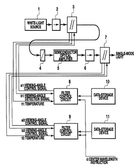
Fig. 1 shows a first embodiment of a light generation method
and a light source according to the present invention. The light
generation method and light source according to the first
embodiment are comprised of a white-light source 1, isolators
2 and 6, disc-shaped optical filters 3, 7, a polarization
controller 4, a semiconductor optical amplifier 5, filter
control circuits 8; 9, and data-storage devices 10, 11.
A white-light output from the white-light source 1 and
having wavelength components over a wide band on a wavelength
spectrum passes through the isolator 2 and is than filtered by
the disc-shaped optical filter 3. A light transmitted through
the filter 3 is input to the semiconductor optical amplifier
5 having its polarization plane controlled by the polarization
controller 4. An output from the amplifier 5 is filtered by the
disc-shaped optical filter 7 via the isolator 6 to generate a
single-mode light having a small spectral bandwidth and high
outputs. Polarization control by the polarization controller
- 33 -
CA 02295353 2003-03-20
4 corresponds to control of the polarization plane of an input
light to be adjustable to the semiconductor optical amplifier 5 ,
thereby so as to obtain a maximum gain from the amplifier 5.
If the white-light source 1 and the semiconductor optical
amplifier 5 are independent of polarization, the polarization
controller 4 may be omitted.
Upon reception of center transmission wavelength
instructions (d), the disc-shaped optical filters 3 and 7 are
independently controlled by the corresponding filter control
circuits 8 , 9 so that their center transmission wavelengths equal
instructive values indicated in the center transmission
wavelength instructions (d). That is, the filter control
circuit 8 reads data for the disc-shaped optical filter 3
indicating center transmission wavelengths versus control
parameters of optical filters, from the data-storage device 10
with this data stored therein. The circuit 8 subsequently uses
a viewing-angle detection signal b1 obtained by detecting a
viewing-angle of the disc of the optical filter as well as a
temperature t1 to calculate a viewing-angle so that its center
transmission wavelength equals the corresponding instructive
value. The circuit 8 then sends a viewing-angle control signal
al to the optical filter so as to equalize the viewing-angle
with a calculated value. The disc-shaped optical filter 3 is
controlled in this manner.
Likewise, the disc-shaped optical filter 7 is controlled
using the filter control circuit 9 by using data from the
data-storage device 11 storing data of center transmission
wavelengths versus control parameters of optical filters as well
as a viewing-angle detection signal b2 and a temperature t2 to
- 34 -
CA 02295353 2000-O1-12
calculate a target viewing-angle, and sending a viewing-angle
control signal a2.
Fig. 4 shows a configuration of the disc-shaped optical
filter 3, 7. A disc-shaped filter 31 in a main body filters an
incident light in a wavelength domain by allowing collimated
beams (parallel lights) emitted from an optical fiber 34 to enter
the disc perpendicularly or almost perpendicularly to a disc
surface, and allowing a transmitted light to enter another
optical fiber 36. The disc-shaped filter 31 has marks 38 applied
to its outer periphery and which are detected to determine a
position through which the collimated beams are allowed to pass .
A typical example of such mark detection means is a method for
using a light emitting diode ( LED ) as a light source and detecting,
below the diode 32, a change in a light irradiated portion caused
by the mark 38 to determine a viewing-angle O as positional
information. This method is implemented by a rotary encoder 32a.
The disc-shaped filter 31 has its center transmission
wavelength-tunable depending on the viewing-angle0 , so that it
rotates the disc around its rotation axis to vary the
viewing-angle O and thus the center transmission wavelength.
Means for rotating the disc may be an ultrasonic motor 30 that
can be formed to be very small.
Fig. 5 shows the structure of a filter section of the
disc-shaped filter 31. A~function for filtering wavelengths is
based on a wavelength selection function of an optical resonator
37 consisting of a layer called a "wedge layer 38" that is located
between high-ref lectivity layers ( HR ) . The wedge layer 38 has
a thickness almost half an effective wavelength, which is
determined taking into consideration a refractive index with
- 35 -
. CA 02295353 2003-03-20
which a light passes through a medium. The high-reflectivity
layers 39 have a thickness one fourth of the effective wavelength
as well as different refractive indices and are alternatively
laminated. In such a film structure, the wedge layer 38 of
thickness (h) is formed in a substrate of SiOz or the like linearly
or almost linearly relative to the viewing-angleU to enable the
center transmission wavelength to be filtered in proportion or
almost proportion to the viewing-angle U. An antireflection
coating 40a is applied to a rear surface of the substrate 40
to prevent undesirable reflection from the substrate.
With such a configuration, if the viewing-angle0 of the
disc is calibrated as a function of a center transmission
wavelength using the temperature as a parameter and this data
is stored in the data-storage devices 10, 1Z, as shown in Fig.
1, and when a center transmission wavelength is provided as an
instructive value, then a temperature can be measured at a
location near the installed disc-shaped filter to calculate an
optimal value.
The above first embodiment allows a transmitted light
obtained by filtering a white-light using the optical filter
to pass through the set of the semiconductor optical amplifier
5 and the optical filter 7 in order to increase outputs while
reducing the wavelength spectrum. Larger effects, however, can
be obtained by allowing the light to pass through a large number
of sets of the semiconductor optical amplifier and the optical
filter.
(Second Embodiment)
Fig. 2 shows a second embodiment of a light generation
method and a light source according to the present invention.
- 36 -
CA 02295353 2003-03-20
The light generation method and light source according to the
second embodiment are comprised of an optical ring consisting
of a semiconductor optical amplifier 5, the isolator 2, the
disc-shaped optical filter 3, an optical amplifier 22, an optical
power divider 24, an optical attenuator 23, and the polarization
controller 4 so that a single-mode light can be obtained from
the optical power divider 24.
A single-mode light is obtained by circulating lights
generated by the semiconductor optical amplifier 5 and the
optical amplifier 22, through the optical ring as seeds. That
is, the semiconductor optical amplifier 5 and the optical
amplifier 22, have effects similar to those of the white-light
source 1 in the first embodiment. The attenuator 23 controls
a circulation gain so as to prevent laser oscillation in the
optical ring. As regards this, if the semiconductor optical
amplifier 5 has a high gain, the optical amplifier 22 may be
omitted.
Upon reception of the center transmission wavelength
instruction (d), the disc-shaped optical filter is controlled
by reading data for the disc-shaped optical filter 3 indicating
center transmission wavelengths versus control parameters of
optical filters, from the data-storage device 13 with this data
stored therein, and using a viewing-angle detection signal b3
and a temperature t3 to calculate an optimal viewing-angle in
order to generate a viewing-angle control signal a3 , as in the
first embodiment.
With such a configuration, despite its simplicity, a
filtered single-mode light can be efficiently amplified while
reducing the wavelength spectrum, thereby obtaining a
- 37 -
CA 02295353 2003-03-20
single-mode light having higher outputs and a smaller spectra.
bandwidth than the single-mode light in th'e first embodiment.
(Third Embodiment)
Fig. 3 shows a third embodiment of a light generation method
and a light source according to the present invention. The light
generation method and light source according to the third
embodiment are comprised of an optical ring consisting of the
semiconductor optical amplifier 5, the isolator 2, an
acoustooptical filter 26 , an optical amplifier 22 , the optical
power divider 24, the optical attenuator 23, and the polarization
controller 4 so that a single-mode light can be obtained from
the optical power divider 24. Such a configuration is the same
as that of the second embodiment.
The acoustooptical filter 26 is comprised of a dielectric
waveguide formed using as a material an electrical engineering
crystal that utilizes a phenomenon in which the refractive index
varies with a voltage and of an electrode formed in the waveguide
and allowing electric signals within a microwave frequency band
to be superposed together. In the acoustooptical filter 26,
upon external application of an AC electric signal, the
refractive index is spatially modulated in such a way as to
correspond to the frequency of the signal. The use of the
periodicity of such a spatial modulation can be used to filter
a light having a wavelength corresponding to the frequency of
an electric signal.
According to the third embodiment, the relationship
between the center transmission wavelength of the
acoustooptical filter 26 and the frequency of electric signals
is stored in the data-storage device 29 as data of center
- 38 -
CA 02295353 2000-O1-12
transmission wavelengths versus control parameters of optical
filters . Upon reception of the center transmission wavelength
instruction, this data is read, and the electrical oscillator
27 is controlled by an electrical-oscillator control circuit
28 so that the center transmission wavelength of the
acoustooptical filter equals the instructive value. An
electric signal output from the electrical oscillator 27 is
applied to the acoustooptical filter 26 to obtain a single-
mode light having a center transmission wavelength equal to the
to instructive value.
Since the center transmission wavelength of the
acoustooptical filter 26 is promptly controlled by means of the
frequency of the applied electric signal, the center
transmission wavelength of the single-mode light can be switched
at a much higher speed ( - ~c s ) than that in the first or second
embodiment.
(Fourth Embodiment)
Fig. 8 shows a fourth embodiment of a stabilized
single-mode light source according to the present invention.
20 The stabilized single-mode light source according to this
embodiment is comprised of a semiconductor optical amplifier
with gain saturation (reference: Kiyoshi NAKAGAWA et al.
"Optical Amplifiers and Their Applications" , Ohm Co . , Ltd . ) 41,
an optical filter 42, an optical power divider 43, and an optical
attenuator 44, all of which are connected together in the form
of a ring, wherein a light output (a single-mode light) is
externally obtained from the optical power divider 43.
The optical attenuator 44 is comprised, for example, of
a ND filter that utilizes attenuation of absorption by a metal
- 39 -
CA 02295353 2000-O1-12
thin film, and adjusts the attenuation so that a mode circulating
through the optical ring is equal to or smaller than a laser
oscillation threshold. The optical filter 42 is generally a
dielectric multilayer film filter but may be comprised of a
combination of a fiber grating and an optical circulator.
The semiconductor optical amplifier 41 increases light
intensity in accordance with the following differential
equation:
~ I(z) - {g(I)-a}I(z) (12)
where I denotes light intensity, (g) denotes a gain factor, ( cx )
denotes a loss to a waveguide, and (z) denotes a propagation
distance. On the other hand, the gain saturation is expressed
as follows
g(I)=go/(1+I/Isat) (13)
where go indicates a gain factor without a light input and Igat
( = h v ~ msat ) indicates saturated light intensity.
A light incident on the semiconductor optical amplifier
is amplified during propagation, whereas its gain decreases with
increasing light intensity as shown in Equation 13. When the
gain equals the waveguide loss (a), a net gain becomes zero.
Subsequently, the light intensity does not increase. The light
intensity Ic is expressed as follows:
Ic = (go/a'-1)Isat (14)
- 40 -
CA 02295353 2000-O1-12
w
If the length L of the semiconductor optical amplifier is so
small that the light intensity does not reach Ic, the output
light intensity of the semiconductor optical amplifier varies
depending on the input light intensity. If, however, L is
sufficiently large, the semiconductor optical amplifier has a
fixed output light intensity Ic irrespective of the input light
intensity.
(Fifth Embodiment)
Fig. 9 shows a fifth embodiment of a stabilized single-mode
light source according to the present invention. The stabilized
single-mode light source according to this embodiment is
comprised of an erbium-doped optical-fiber amplifier acting as
a wide-band white-light source (EDFA, reference) 45, the
optical filter 42, the semiconductor optical amplifier 41 with
gain saturation, the optical power divider 43, and the optical
attenuator 44 , all of which are connected together in the form
of a ring, wherein a light output (a single-mode light) is
externally obtained from the optical power divider 43.
The optical filter 42 , the EDFA 45 , and the semiconductor
optical amplifier 41 may be arranged in this order. In addition,
the EDFA may be comprised of two sections having the optical
filter 42 located therebetween.
The EDFA 45 is characterized by its outputs larger than
spontaneous emissions from the semiconductor optical amplifier
41 and enables a wavelength to be selected from a wide wavelength
range. In addition, by independently controlling the output
from the EDFA 45 and the optical attenuator 44 , the input light
intensity of the semiconductor optical amplifier 41 can be
- 41 -
' CA 02295353 2003-03-20
controlled while keeping the net loss to the optical ring
constant. This function is convenient in keeping constant the
net loss that directly affects the spectral bandwidth in order
to regulate the optical ring without the need to change the
spectral bandwidth. Consequently, the configuration of this
embodiment can compensate for the variation of the
characteristics of the semiconductor optical amplifier 41 to
optimize the optical ring.
According to the configurations of the fourth and fifth
embodiments shown above, the wavelength of the output light
( single-mode light ) is selected and fixed by the optical filter
42. An optical filter capable of varying the selected
wavelength is required for varying the wavelength of the output
light ( single-mode light ) . In a sixth and a seventh embodiment ,
which are shown below, an example of the configuration of the
fourth embodiment shown in Fig. 8 is shown in which a wide-
band continuous wavelength-tunable filter is used instead of
the optical filter 42. This example is similarly applicable to
the f if th embodiment shown in Fig . . 9 .
The continuous wavelength-tunable filter is shown in the
sixth embodiment as a disc-shaped wavelength-tunable optical
filter comprised of a dielectric multilayer film filter with
a circularly changed center transmission wavelength (reference
~2: Y. Katagiri et al., "Synchro-Scanned Rotating Tunable
Optical Disc Filter for Wavelength Discrimination", IEEE
Photonics Technology Letters, vo1.10, no.3, 1998), and in the
seventh embodiment as an acoustooptical wavelength-tunable
optical filter (reference03: Jiro KOYAMA et al., "Light Wave
Electronic Engineering", Corona Co., Ltd.).
- 42 -
CA 02295353 2003-03-20
(Sixth Embodiment)
Fig. 10 shows a sixth embodiment of a stabilized
single-mode light source according to the present invention.
The stabilized single-mode light source according to this
embodiment has a sweep wavelength-tunable filter module 50
including the disc-shaped wavelength-tunable filter 51, instead
of the optical filter 42 in the fourth embodiment.
The sweep wavelength-tunable filter module 50 is comprised
of a disc-shaped wavelength-tunable filter 51, a DC servo motor
52 for rotating the filter 51, and a PLL circuit 53 for
controlling rotation of the filter 51, and sweeps a selected
wavelength in synchronism with an external clock 54 input to
the disc-shaped wavelength-tunable filter 51. The rotation of
the disc-shaped wavelength-tunable filter 51 must be
sufficiently slower than the circulation through the optical
ring . Since a typical rotation speed is 200 rps at most , a stable
output light can be obtained while preventing attenuated
circulation of a light from being affected by the rotation speed.
In addition, the semiconductor optical amplifier 41 has
different gains depending on the selected wavelength, so that
the light source includes a gain control section 55 synchronizing
with the external clock 54, for controlling the gain of the
semiconductor optical amplifier 4l in synchronism with
switching of the selected wavelength. To control the gain, for
example, the value of a bias current injected into the
semiconductor optical amplifier 41 is controlled.
Although this embodiment has been described in conjunction
with the example in which the disc-shaped wavelength-tunable
filter is used as a continuous wavelength-tunable filter, a
- 43 -
CA 02295353 2000-O1-12
r r
linear wavelength-tunable filter comprised of a dielectric
multilayer film filter with a linearly changed center
transmission wavelength may be used and linearly moved.
(Seventh Embodiment)
Fig. 11 shows a seventh embodiment of a stabilized
single-mode light source according to the present invention.
The stabilized single-mode light source according to this
embodiment has a sweep wavelength-tunable filter module 60
including an acoustooptical wavelength-tunable optical filter
(AOTF) 61, instead of the optical filter 42 in the fourth
embodiment.
The sweep wavelength-tunable optical filter module 60 is
comprised of the AOTF 61 for selecting a wavelength depending
on the frequency of an applied RF signal, a driver 62 for applying
a RF signal to the AOTF 61, and a sweeper 63 for sweeping the
frequency of a RF signal. The module 60 sweeps the selected
wavelength synchronously with an external clock 54 input to the
sweeper 63. Since the sweep speed of the AOTF 61 is very high
due to its dependence on an electric circuit, it must be set
taking into account the time required for circulation through
the optical ring. If the sweep speed becomes higher than the
circulation speed, the selected wavelength is changed before
a noise wave has sufficiently circulated through the optical
ring, thereby making it difficult to restrain intensity noise.
The gain control section 55 is similar to that in the sixth
embodiment.
(Eighth Embodiment)
Fig. 12 shows an eighth embodiment of a stabilized
single-mode light source according to the present invention.
- 44 -
CA 02295353 2003-03-20
The stabilized single-mode light source according to this
embodiment is characterized in that the optical
filter 42 in the fifth embodiment shown in Fig. 9 is replaced
with an array waveguide grating filter (AWG) 71 to obtain
single-mode lights of a plurality of wavelengths at a time . The
semiconductor optical amplifier 41, the optical power divider
43, and the optical attenuator 44 correspond to different
wavelengths obtained by the AWG 71 by means of splitting. The
AWG 71 is further used as an optical merger to merge lights of
ZO corresponding wavelengths together and then to input the merged
light to the EDFA 45.
The AWG 71 is comprised of an input waveguide, a first
fan-shaped slab waveguide, a waveguide array consisting of a
plurality of waveguides each having a sequentially larger length,
a second fan-shaped slab waveguide, and an output waveguide,
all of which are connected in this order. The AWG 71 functions
as a merger/splitter.
A wide-band white-light output from the EDFA 45 is split
into a plurality of wavelengths ~ 1, ~ 2 , ~ 3 , ~ 4 . That is , a
20 plurality of bands pass through the AWG 71. Since the bands have
corresponding intensity noises that are not correlated to one
another (that belong to different populations), they are
individually input to semiconductor optical amplifiers 41-1 to
41-4 with gain saturation. Part of a light passing through each
of the semiconductor optical amplifiers 41-1 to 41-4 is branched
to the exterior via a corresponding one of the optical power
dividers 43-1 to 43-4, while the remaining part is input to a
corresponding one of the subsequent optical attenuators 44-1
to 44-4 . A light passing through each of the optical attenuators
- 45 -
CA 02295353 2000-O1-12
44-1 to 44-4 is input to a predetermined port of the AWG 71 and
merged with one port before being input to the EDFA 45.
By arranging the optical attenuators 44-1 to 44-4 so as
to correspond to each splitting channel, laser oscillation can
be prevented even at particular wavelengths based on the
dependence of the gain on the wavelength, thereby obtaining
generally equal light outputs at all wavelengths.
In addition, in each of the above embodiments, an optical
isolator may be placed at an appropriate position for defining
a light propagation direction in the optical ring.
(Ninth Embodiment)
Fig. 13 shows a ninth embodiment of a light generation
method and a light source according to the present invention.
According to the ninth embodiment, a plurality of
wavelength-tunable optical filters 90, 110 are used to output
a single-mode light having wavelength components over a
particular band of a white-light band by obtaining this light
from a white-light having wavelength components over a wide band
in wavelength domain.
This light source is comprised of optical amplifiers 80 , 100
that are ermium-doped optical-fiber amplifiers, wavelength-
tunable optical filters 90, 110 that are disc-shaped optical
filters, a disc rotating motor 99 for rotating a disc-shaped
filter of the wavelength-tunable optical filter 90, a disc
rotating motor 119 for rotating a disc-shaped filter of the
wavelength-tunable optical filter 110, and an optical-filter
control section 130 for outputting rotation angle instruction
signals to the disc rotating motors 99, 119 to control the
transmission bands of the wavelength-tunable optical filters
- 46 -
CA 02295353 2003-03-20
90, 110 as shown in Fig. 13. A white-light from the optical
amplifier 80 is filtered on passing through the
wavelength-tunable optical filter 90, the optical amplifier 100,
and the wavelength-tunable optical filter 1I0 in this order.
The optical-filter control section 130 is composed of a
CPU 132 forcontrolling calculations and the entire system based
on a control program, a ROM 134 for storing the control programs
of the CPU 132 in predetermined areas beforehand, a main memory
136 for storing data read from the ROM 134 or the like as well
as calculation results required for calculation processes
executed by the CPU 132, a peripheral-equipment interface 138
for communicating data outputs to the disc rotating motors 99,
119 , an input device I40 consisting of a keyboard, a mouse , etc .
for enabling data inputs as a human interface, a graphic
interface I42 for converting display data stored in a particular
area of the main memory 136 into an image signal and outputting
it, an output display 144 for displaying a screen based on the
image signal, a portable storage media drive I46, and a mass
storage device 148. These devices 132 to 148 are connected
together via a bus 149 so as to transmit and receive data, wherein
the bus acts as a signal line for transferring data.
The main memory 136 has a VRAM that is a particular area
for storing display data for display on an output display 144,
and the VRAM is independently accessible from the graphic
interface I42 and the CPU 132. The graphic interface 142
sequentially reads display data from the VRAM with a
predetermined cycle starting with a leading address, and
converts read display data into an image signal to output it
to the output display 144.
- 47
CA 02295353 2000-O1-12
", .
Next, a configuration of the wavelength-tunable optical
filters 90, 110 will be described with reference to Figs. 14
to 16. Figs. 14 and 15 show the configuration of the
wavelength-tunable optical ffilters 90, 110, and Fig. 16 shows
a filtering characteristic of the wavelength-tunable optical
filters 90, 110.
Since the wavelength-tunable optical filters 90, 110 are
configured to have identical functions, only the configuration
of the wavelength-tunable optical filter 90 will be explained
and the description of the wavelength-tunable optical filter
110 will be omitted.
The wavelength-tunable optical filter 90 is a disc-shaped
optical filter having a predetermined transmission bandwidth
and a circularly changed center transmission wavelength, as
shown in Fig. 14. The optical filter 90 carries out filtering
by varying the center transmission wavelength depending on the
rotation angle of the disc-shaped filter to allow a light to
enter a disc surface at a fixed position thereof to pass through
in a rotation axis direction.
The disc-shaped filter of the wavelength-tunable optical
filter 90 is comprised of a glass layer 91 consisting of Si02
and acting as a substrate layer and a filter layer 92 deposited
thereon and having a circularly changed center transmission
wavelength. The filter layer 92 is comprised of a typical
dielectric multilayer film comprised of a high-reflectivity
layer 92a having a fixed thickness along a circumferential
direction, a wedge layer 92b laminated thereon and having a
thickness varying in the circumferential direction (the
thickness increases in proportion to an increase in central angle
- 48 -
CA 02295353 2003-03-20
between 0 and n , while decreasing in proportion to an increase
in central angle between ~ and 2n), and a high-reflectivity
layer 92c having a fixed thickness along the circumferential
direction. The transmission wavelength and the transmission
bandwidth are determined by the structure of the filter layer
92, and in particular, the center transmission wavelength is
determined by the thickness of the wedge layer 92b of the filter
layer 92 . A disc surface opposed to the glass layer 91 is covered
with a wide-band anti-reflection coating.
The disc-shaped filter 90 has a filtered light enter its
surface on the side of the filter layer 91 at a fixed position
of the surface and also has a plurality of marks 93 circularly
provided on its outer periphery at predetermined intervals, as
shown in Fig. 15. The optical filter control section 130 uses
an optical reader (not shown) to read the marks 93 to control
the viewing-angle of the disc-shaped filter.
The disc-shaped filter of the wavelength-tunable optical
filter 90 has a filtering characteristic such as one shown in
Fig. 16 and shows a Lorentzian spectrum profile. The center
transmission wavelength and the rotation angle of the disc-
shaped filter have a generally linear relationship.
Referring back to Fig. 13, the ROM 134 stores data of center
transmission wavelengths versus control parameters of optical
filters, the data being used to determine the transmission
bandwidths of the wavelength-tunable optical filters 90, 110
and comprising different center transmission wavelengths of the
wavelength-tunable optical filters 90, 1I0 associated with
corresponding rotation angles of the disc-shaped filters.
The CPU 132 is comprised of a microprocessing unit MPU or
- 49 -
CA 02295353 2000-O1-12
,,
the like, and to control the wavelength-tunable optical filters
90, 110, the CPU 132 activates a corresponding control program
stored in a predetermined area of the ROM 134 to execute
processing required for controlling the wavelength-tunable
optical filters 90, 110.
In this control processing, when a center transmission
wavelength is input from the input device 140 or the like as
an instructive value of the center transmission wavelength of
the wavelength-tunable optical filters 90, 110, the data of
l0 center transmission wavelengths versus control parameters of
optical filters is read from the ROM 134, and a rotating angle
instruction signal is simultaneously output to the disc rotating
motors 99 , 119 based on this data so that the center transmission
wavelength of the transmission band of the wavelength-tunable
optical filters 90, 110 equals the center transmission
wavelength provided as the instructive value.
Next, operation of the ninth embodiment will be described
with reference to Fig. 17. Fig. 17 is a graph showing
characteristics of the wavelengths of lights output from the
20 optical amplifier 100 and the wavelength-tunable optical filter
110.
First , when a center transmission wavelength is input from
the input device 140 or the like as instructive value of the
center transmission wavelength of the wavelength-tunable
optical filters 90, 110, the optical-filter control section 130
reads from the ROM 134 the data of center transmission
wavelengths versus control parameters of optical filters, and
simultaneously outputs rotation angle instruction signals to
the disc rotating motors 99 , 119 based on this data so that the
- 50 -
CA 02295353 2000-O1-12
center transmission wavelength of the transmission bands of the
wavelength-tunable optical filters 90, 110 equals the center
transmission wavelength provided as the instructive value.
Based on the input rotation angle instruction signal, the disc
rotating motors 99, 119 rotate the disc-shaped filters of the
wavelength-tunable optical filters 90, 110 to equalize the
center transmission wavelength of the wavelength-tunable
optical filters 90, 110 with the center transmission wavelength
provided as the instructive value.
Once the center transmission wavelength of the
wavelength-tunable optical filters 90, 110 has been determined,
the optical amplifier 80 outputs a white-light containing a
spontaneous emission, which is first filtered by the
wavelength-tunable optical filter 90. Thus, since components
in the white-light band other than those in a particular band
around the center transmission wavelength are filtered, a light
transmitted through the wavelength-tunable optical filter 90
has only the components in the particular band around the center
transmission wavelength.
Then, the light transmitted through the wavelength-
tunable optical filter 90 is amplified by the optical amplifier
100 and filtered by the wavelength-tunable optical filter 110.
After this amplification, the light transmitted through the
wavelength-tunable optical filter 90 contains the spontaneous
emission amplified by the optical amplifier 100, but this
spontaneous emission is filtered by the subsequent
wavelength-tunable optical filter 110. As a result, wavelength
components in the white-light from the optical amplifier 80 other
than those in a predetermined transmission band around the center
- 51 -
CA 02295353 2003-03-20
transmission wavelength of the wavelength-tunable optical
filters 90, 110 are filtered, while the wavelength components
in the predetermined transmission band around the center
transmission wavelength of the wavelength-tunable optical
filters 90, 110 are amplified.
Then, the light transmitted through the wavelength-
tunable optical filter 110 is output as a single-mode light.
The single-mode light is obtained by carrying out processing
comprising such amplification and filtering at least once.
In this manner, this embodiment is comprised of the optical
amplifiers 80, 100 and the wavelength-tunable optical filters
90, 110 having a predetermined transmission bandwidth and a
predetermined center transmission wavelength so that a
white-light from the optical amplifier 80 is filtered by the
wavelength-tunable optical filter 90, so that a light
transmitted through the wavelength-tunable optical filter 90
is amplified by the optical amplifier 100, and so that an
amplified light from the optical amplifier 100 is filtered by
the wavelength-tunable optical filter 110 to obtain a light
transmitted through the wavelength-tunable optical filter 110,
as a single-mode light. Accordingly, wavelength components in
the white-light from the optical amplifier 80 other than those
in a predetermined transmission band around the center
transmission wavelength of the wavelength-tunable optical
filters 90, 110 are filtered, while the wavelength components
in the predetermined transmission band around the center
tra~smissi.on wavelength of the wavelength-tunable optical
filters 90, 110 are amplified, thereby providing a high-output
single-mode light without degrading the spectral purity of the
- s2 -
CA 02295353 2000-O1-12
single-mode light, compared to the prior art.
In addition, according to this embodiment, the
wavelength-tunable optical filters 90, 110 are each a disc-
shaped optical filter having a predetermined transmission
bandwidth and a circularly changed center transmission
wavelength; when a center transmission wavelength is provided
as instructive value, the optical-filter control section 130
reads from the ROM 134 the data of center transmission
wavelengths versus control parameters of optical filters, and
controls the rotation angles of the disc-shaped filters of the
wavelength-tunable optical filters 90, 110 based on the read
data so that the center transmission wavelength of the
transmission bands of the wavelength-tunable optical filters
90, 110 equals the center transmission wavelength provided as
the instructive value. Consequently, the center transmission
wavelength of the wavelength-tunable optical filters 90, 110
can be varied at a high speed despite the very simple
configuration, thereby not only enabling the size and costs of
the conventional filter module to be substantially reduced but
also enabling the center transmission wavelength of the
wavelength-tunable optical filters 90, 110 to be varied with
timings required by the system.
Next , a tenth embodiment of the present invention will be
explained with reference to the corresponding drawings. Fig.
18 shows the tenth embodiment of a light generation method and
a light source according to the present invention.
The tenth embodiment is an application to a case in which
a single wavelength-tunable optical filter 120 is used to output
a single-mode light having components in a particular band of
- 53 -
CA 02295353 2000-O1-12
a white-light band by obtaining this light from a white-light
having wavelength components over a wide-band in the wavelength
domain. Only those components of this embodiment that are not
included in the ninth embodiment will be described below, while
the description of duplicate portions will be omitted.
This light source is composed of the optical amplifiers
80, 100, the wavelength-tunable optical filter 120 that is a
disc-shaped filter, a disc rotating motor 129 for rotating a
disc-shaped filter of the wavelength-tunable optical filter 120,
and an optical-filter control section 130 so that a white-light
from the optical amplifier 80 is filtered as it passes through
the wavelength-tunable optical filter 120, the optical
amplifier 100, and the wavelength-tunable optical filter 120
in this order.
Next, a configuration of the wavelength-tunable optical
filter 120 will be described with reference to Fig. 19. In the
wavelength-tunable optical filter 120, a path for collimate
beams through an optical fiber joining the optical amplifier
80 and the wavelength-tunable optical filter 120 together and
an optical fiber joining the optical amplifier 100 and the
wavelength-tunable optical filter 120 is formed as a folding
path using prism mirrors 94a, 94b, 95a, 95b. As seen in Fig.
19, the disc-shaped filter has two prism mirrors 94a, 94b
arranged on its side of the filter layer 92 along a radial
direction of the disc at locations close to each other and to
a disc-shaped filter surface, and also has two prism mirrors
95a, 95b arranged on its side of the glass layer 91 at locations
opposed to the prism mirrors 94a, 94b relative to the disc-
shaped filter surface and at locations close to each other and
- 54 -
CA 02295353 2000-O1-12
n Y
to the disc-shaped filter surface.
When a white-light from the optical amplifier 80 is input
to the prism mirror 94a from a radial direction of the disc-shaped
filter through the optical fiber or the like, this incident light
is reflected in the rotation axis direction of the disc-shaped
filter and then output to the prism mirror 95a through the
disc-shaped filter. When a light transmitted through the
disc-shaped filter is input to the prism mirror 95a, this
incident light is reflected in the radial direction of the
disc-shaped filter and then output to the optical amplifier 100
through the optical fiber or the like.
On the other hand, when an amplified light from the optical
amplifier 100 is input to the prism mirror 94b from the radial
direction of the disc through the optical fiber or the like,
this incident light is reflected in the rotation axis direction
of the disc-shaped filter and then output to the prism mirror
95b through the disc-shaped filter. When a light transmitted
through the disc-shaped filter is input to the prism mirror 95b,
this incident light is reflected in the radial direction of the
disc-shaped filter and then output as a single-mode light through
the optical fiber or the like.
In this manner, since the prism mirrors 94a, 94b and the
prism mirrors 95a, 95b are arranged close to each other in the
radial direction of the disc-shaped filter, the center
transmission wavelength in the path from the prism mirror 94a
to the prism mirror 95a is almost equal to the center transmission
wavelength in the path from the prism mirror 94b to the prism
mirror 95b. In this case, the transmission bandwidths of these
two paths are almost equal.
- 55 -
CA 02295353 2000-O1-12
Next, operation of the tenth embodiment will be described.
First, when a center transmission wavelength is input from the
input device 140 or the like as instructive value of the center
transmission wavelength of the wavelength-tunable optical
filter 120, the optical-filter control section 130 reads from
the ROM 134 the data of center transmission wavelengths versus
control parameters of optical filters, and outputs a rotation
angle instruction signal to the disc rotating motor 129 based
on this data so that the center transmission wavelength of the
transmission band of the wavelength-tunable optical filter 120
equals the center transmission wavelength provided as the
instructive value. Based on the input rotation angle
instruction signal, the disc rotating motor 129 rotates the
disc-shaped filter of the wavelength-tunable optical filter 120
to equalize the center transmission wavelength of the
wavelength-tunable optical filter 120 with the center
transmission wavelength provided as the instructive value.
Once the center transmission wavelength of the
wavelength-tunable optical filter 120 has been determined, the
optical amplifier 80 outputs a white-light containing a
spontaneous emission, which is first filtered by the
wavelength-tunable optical filter 120. Thus, since components
in the white-light band other than those in a particular band
around the center transmission wavelength are filtered, a light
transmitted through the wavelength-tunable optical filter 120
has only the components in the particular band around the center
transmission wavelength.
Then, the light transmitted through the wavelength-
tunable optical filter 120 is amplified by the optical amplifier
- 56 -
CA 02295353 2003-03-20
100 and filtered by the wavelength-tunable optical filter 12U
again. After this amplification, the light transmitted through
the wavelength-tunable optical filter 120 contains the
spontaneous emission amplified by the optical amplifier 100,
but this spontaneous emission is filtered by the subsequent
wavelength-tunable optical filter 120. As a result, wavelength
components in the white-light from the optical amplifier l00
other than those in a predetermined transmission band around
the center transmission wavelength of the wavelength-tunable
optical filter 120 are filtered, while the wavelength components
in the predetermined transmission band around the center
transmission wavelength of the wavelength-tunable optical
filter 120 are amplified.
Then, the light transmitted through the wavelength-
tunable optical filter 120 is output as a single-mode light.
The single-mode light is obtained by carrying out processing
comprising such amplification and filtering at least once.
In this manner, this embodiment is comprised of the optical
amplifiers 80, 100 and the wavelength-tunable optical filter
120 having a predetermined transmission bandwidth and a
predetermined center transmission wavelength so that a
white-light from the optical amplifier 80 is filtered by the
wavelength-tunable optical filter 120, so that a light
transmitted through the wavelength-tunable optical filter 120
is amplified by the optical amplifier 100, and so that an
amplified light from the optical amplifier 100 is filtered by
the wavelength-tunable optical filter 120 again to obtain a light
transmitted through the wavelength-tunable optical filter 120,
as a single-mode light. Accordingly, wavelength components in
- 57 -
CA 02295353 2000-O1-12
i i
the white-light from the optical amplifier 80 other than those
in a predetermined transmission band around the center
transmission wavelength of the wavelength-tunable optical
filter 120 are filtered, while the wavelength components in the
predetermined transmission band around the center transmission
wavelength of the wavelength-tunable optical filter 120 are
amplified, thereby providing a high-output single-mode light
without degrading the spectral purity of the single-mode light ,
compared to the prior art.
In addition, according to this embodiment, the
wavelength-tunable optical filter 120 is a disc-shaped optical
filter having a predetermined transmission bandwidth and a
circularly changed center transmission wavelength; when a
center transmission wavelength is provided as instructive value,
the optical-filter control section 130 reads from the ROM 134
the data of center transmission wavelengths versus control
parameters of optical filters, and controls the rotation angles
of the disc-shaped filters of the wavelength-tunable optical
filter 120 based on the read data so that the center transmission
wavelength of the transmission bands of the wavelength-tunable
optical filter 120 equals the center transmission wavelength
provided as the instructive value. Consequently, the center
transmission wavelength of the wavelength-tunable optical
filter 120 can be varied at a high speed despite the very simple
configuration, thereby not only enabling the size and costs of
the conventional filter module to be substantially reduced but
also enabling the center transmission wavelength of the
wavelength-tunable optical filter 120 to be varied with timings
required by the system.
- 58 -
A
CA 02295353 2000-O1-12
Furthermore, according to this embodiment, the path for
collimate beams through the optical fiber joining the optical
amplifier 80 and the wavelength-tunable optical filter 120
together and the optical fiber joining the optical amplifier
100 and the wavelength-tunable optical filter 120 is formed as
a folding path using the prism mirrors 94a, 94b, 95a, 95b.
Consequently, a high-output single-mode light can be obtained
using the single wavelength-tunable optical filter 120, thereby
enabling the filter module to be thin enough to be mounted on
a board .
According to the ninth embodiment , a white-light from the
optical amplifier 80 is filtered as it passes through the
wavelength-tunable optical filter 90, the optical amplifier 100,
and the wavelength-tunable optical filter 110 in this order so
that a single-mode light is obtained by executing processing
comprising such amplification and filtering once. The present
invention, however, is not limited to this aspect, but a
single-mode light may be obtained by executing processing
comprising such amplification and filtering a number of times.
Likewise , according to the tenth embodiment , a white-light
from the optical amplifier 80 is filtered as it passes through
the wavelength-tunable optical filter 120, the optical
amplifier 100, and the wavelength-tunable optical filter 120
in this order so that a single-mode light is obtained by executing
processing comprising such amplification and filtering once.
The present invention, however, is not limited to this aspect,
but a single-mode light may be obtained by executing processing
comprising such amplification and filtering a number of times.
In addition, the ninth and tenth embodiments have been
- 59 -
CA 02295353 2000-O1-12
".
described in conjunction with the case in which the corresponding
control program stored in the ROM 134 is executed to control
the wavelength-tunable optical filters 90 and 110 or the
wavelength-tunable optical filter 120. The present invention,
however, is not limited to this aspect, but a program indicating
a corresponding procedure may be read from a storage medium with
this program stored therein to the main memory 136 for execution.
The storage medium may be a semiconductor storage medium
such as a RAM or a ROM, a magnetic storage medium such as a FD
l0 or a HD, or a magnetic storage/optical reading storage medium
such as CD, CDV, LD, or DVD, and includes any storage medium
as long as it can be read by a computer whether it uses an
electronic, a magnetic, or an optical reading method.
In the ninth and tenth embodiments, the optical-filter
control section 130 corresponds to optical-filter control means,
the ROM 134 corresponds to storage means, and a white-light from
the optical amplifier 80 corresponds to a spontaneous emission.
As described above, the present invention provides a light
generation method and a light source for outputting a single-mode
20 light by using an optical filter to filter a white-light having
wavelength components over a wide-band in a wavelength domain,
wherein the single-mode light is obtained by carrying out, at
least once, the process of using an optical amplifier as a light
source for generating the white-light, filtering the optical
amplifier using the optical filter, and using the amplifier to
amplify a light transmitted through the optical filter and
filtering the amplified light transmitted through the optical
filter using an optical filter having a center transmission
wavelength equal to the center transmission wavelength of the
- 60 -
CA 02295353 2003-03-20
above optical filter. Thus, a single-mode light having a small
wavelength spectral bandwidth and high outputs can be easily
generated at an arbitrary center transmission wavelength.
In addition, the stabilized single-mode light source
according to the present invention can easily generate, at an
arbitrary wavelength, an incoherent single-mode light having
a small wavelength spectral bandwidth and restrained intensity
noise.
In particular, the wavelength of a single-mode light can
be selected from a wide wavelength range when the light source
is comprised of an optical fiber amplifier acting as an optical
amplifying medium to output a wide-band white-light and a
semiconductor optical amplifier having gain saturation. In
addition, by independently controlling the excitation level of
the optical-fiber amplifier and attenuation provided by the
optical attenuator, the light source can compensate for the
variation of the characteristics of the semiconductor optical
amplifier to optimize an optical ring without the need to change
the spectral bandwidth.
Furthermore, since wavelength components of a spontaneous
emission other than those in a particular band are filtered,
while the wavelength components in the particular band are
amplified, a high-output single-mode light can be obtained
without degrading its spectral purity, compared to the prior
art.
In addition, a high-output single-mode light can be
obtained using a single wavelength-tunable optical filter,
thereby enabling the filter module to be thin enough to be mounted
on a board.
- 61 -
CA 02295353 2003-03-20
Furthermore, the center transmission wavelength of the
optical filter can be varied at a high speed despite the very
simple configuration, thereby not only enabling the size and
costs of the conventional filter module to be substantially
reduced but also enabling the center transmission wavelength
of the optical filter to be varied with timings required by the
system.
The present invention'has been described in detail with
respect to preferred embodiments, and it will now be apparent
from the foregoing to those skilled in the art that changes and
modifications may be made without departing from the invention
in its broader aspects, and it is the intention, therefore, in
the appended claims to cover all such changes and modifications
as fall within the true spirit of the invention.
- 62 -