Note: Descriptions are shown in the official language in which they were submitted.
CA 02295409 2007-09-26
1
OPTICAL POSITION SENSORS
FIELD OF THE INVENTION
The present invention relates generally to object
tracking systems, and specifically to non-contact,
electromagnetic methods and devices for tracking the
lo position and orientation of an object.
BACKGROUND OF THE INVENTION
Non-contact methods of determining the position of
an object based on generating a magnetic field and
measuring its strength at the object are well known in
the art. For example, U.S. patent 5,391,199, and PCT
patent publication W096/05768 describe such systems for
determining the coordinates of a medical probe or
catheter inside the body. These systems typically
include one or more coils within the probe, generally
adjacent to the distal end thereof, connected by wires
to signal processing circuitry coupled to the proximal
end of the probe.
U.S. patent 4,849,692, to Blood, describes a
position tracking system based on detection of a DC
magnetic field. Preferred embodiments described in this
patent are based on detecting electrical currents
generated in response to the field. Mention is made of
the possibility of using a fiberoptic magnetic field
sensor, but the patent gives no further information on
possible implementations of such a sensor in position
measurement.
CA 02295409 2007-09-26
2 -
The use of magneto-optic materials to measure
magnetic field strength is known in the art, as
described, for example, by M.N. Deeter et al., in
"Novel Bulk Iron Garnets for Magneto-Optic Magnetic
Field Sensing, Proceedings of SPIE, Vol. 2922.
Magneto-optic
materials rotate the polarization of polarized light
passing through them, by an amount proportional to the
strength of the magnetic field. The polarization
rotation is characterized by a parameter known as
Verdet's constant, expressed in units of deg/cm/Tesla.
For strongly magneto-optic materials, such as yttrium
iron garnet (YIG), the Verdet constant is about 108.
However, magneto-optic materials exhibit hysteresis,
causing difficulties in field measurement when time-
varying non-constant fields are involved.
Magnetostrictive fiberoptic strain gauges are also
known in the art. For example, the article "Optical
Fibre Magnetic Field Sensors," by K. P. Koo, Optics
Letters,
describes a method for measuring magnetic fields using
magnetostrictive perturbation of a fiberoptic. A grating
is produced within the fiber, for example by irradiating
the fiber with an excimer laser. The grating generally
comprises a periodically varying refractive index within
the fiber. When light having a wavelength equal to twice
the grating spacing is injected into the proximal end of
the fiber, constructive interference of the reflected
waves will give a strong reflection back to the proximal
end. When a mechanical strain is applied to stretch the
fiber, the grating spacing changes, so that the
wavelength response of the reflected light is
CA 02295409 2000-01-13
3 - -
proportional to the mechanical strain and hence to the
magnetic field.
SUMARY OF THE INVENTION
It is an object of some aspects of the present
invention to provide improved position sensing apparatus
based on optical sensing of a magnetic field.
In one aspect of the present invention, the
apparatus is used to determine the position of an
invasive probe within the body of a patient.
In preferred embodiments of the present invention,
apparatus for sensing the position of a catheter
comprises an optical fiber embedded in the catheter,
which senses an external magnetic field that is applied
to the catheter. Light is injected into the fiber at the
proximal end of the catheter and propagates down to the
distal end thereof, where it is modulated by the effect
of the magnetic field, as described below. The modulated
light is reflected back to the proximal end, where it is
monitored to provide a measure of the magnetic field at
the distal end. The magnetic field measurement is used
to determine coordinates of the distal end of the
catheter, by methods of signal analysis similar to those
described in the above-mentioned U.S. patent 5,391,199
and PCT publication W096/05768.
In some preferred embodiments of the present
invention, the fiber is coupled at its distal end to one
face of a magneto-optic crystal, preferably yttrium iron
garnet (YIG), suitably oriented, adjacent to the distal
end of the catheter. An opposing face of the crystal is
coated for reflection. Preferably, the fiber is a
.._._m-.. _.._,.-_ . . _ . _
.._ _ _ __ ..._.___......~
CA 02295409 2000-01-13
4 - -
single-mode, polarization preserving fiber, as is known
in the art. Polarized light is injected into the fiber's
proximal end, and is rotated by the YIG crystal by an
angle proportional to the magnetic field strength. The
polarization of the reflected light returning to the
proximal end is analyzed to determine the field
strength, and hence, the position of the distal end of
the catheter.
Alternatively, there is a polarizer placed between
the distal end of the fiber and the crystal, and the
intensity of the reflected light is detected to
determine the polarization rotation angle. In this
case, it is not necessary that the fiber be of the
polarization- preserving type.
In these preferred embodiments, there is preferably
an additional fiber in the catheter, not coupled to the
crystal, to serve as a temperature reference. Reflection
signals received from the additional fiber are used to
compensate for changes in signals in the sensor fiber
due to temperature changes.
Furthermore, in order to account for hysteresis in
the polarization rotation effect, in preferred
embodiments of the present invention, signal processing
circuitry associated with the catheter preferably tracks
changes of polarization of the light reflected back from
the crystal, to determine where on the hysteresis curve
the sensor is operating.
In other preferred embodiments of the present
invention, the fiber contains a grating structure, as
described in the above-mentioned article by Koo, and is
clad with a magnetostrictive material. The
magnetostrictive material expands or contracts in direct
proportion to the external magnetic field. Such
CA 02295409 2007-09-26
expansion or contraction changes the spacing of the
grating in the fiber, so that the reflected light
intensity may be used to measure the field strength and
thus to determine the position of the catheter, as
5 described above.
Preferably the magnetic field has an AC field
component, at a frequency that is low enough so that the
magnetostrictive material will contract and expand
synchronously with the field variation. Detection of the
reflected light is locked to the magnetic field AC
frequency, so as to cancel out spurious changes in
reflection due to other strains on the catheter, such as
bending.
In some of these preferred embodiments, the fiber
includes several gratings at different points along its
length, each grating having a different, respective
grating spacing. Polychromatic light having wavelengths
corresponding respectively to the different spacings of
the gratings is injected into the fiber, and changes of
intensity at each wavelength are monitored to detect the
magnetic field at (and hence the positions of) the
different grating points along the length of the fiber.
In this manner, a single fiber is used to make multiple
position measurements simultaneously.
In some aspects, there is provided an apparatus for
determining the position of an object, comprising: a
light source; a magnetic-field responsive optical
element, coupled to the object, which receives light
from the light source and modulates the light responsive
to an external AC magnetic field, having a predetermined
CA 02295409 2007-09-26
5a
frequency; a detector, which receives at least a portion
of the modulated light from the magnetic-field
responsive optical element and generates signals
responsive thereto; and signal processing circuitry,
which receives the signals from the detector and
processes the signals to determine the position of the
object.
In some aspects, there is provided a method for
determining the position of an object, comprising:
fixing a magnetic field-responsive optical element to
the object; injecting light into the magnetic field-
responsive optical element; applying a modulated
magnetic field to the object; receiving light from the
magnetic field-responsive optical element and detecting
a modulation in the light responsive to the magnetic
field; analyzing the modulation to determine the
position of the object.
In some aspects, there is provided an elongate
medical probe, having proximal and distal ends, whose
position is tracked within the body of a subject,
comprising: a magnetic-field responsive optical element
adjacent to the distal end, which modulates light
passing therethrough responsive to an externally-applied
magnetic field; and a fiberoptic coupled to transmit
light to the optical element and receive modulated light
from the optical element and convey it to the proximal
end of the probe for analysis of the modulation.
The present invention will be more fully understood
from the following detailed description of the preferred
CA 02295409 2007-09-26
5b
embodiments thereof, taken together with the drawings in
which:
CA 02295409 2000-01-13
6 - -
BRIEF DESCRIPTION OF THE DRAWINGS
Fig. 1A is a schematic illustration showing a
catheter including a fiberoptic position sensor, in
accordance with a preferred embodiment of the present
invention;
Figs. 1B and 1C are schematic illustrations showing
fiberoptic position sensors for use in the catheter of
Fig. 1A, in accordance with alternative preferred
embodiments of the present invention;
Fig. 2 is a graph showing a hysteresis curve
associated with the sensor of Fig. 1A or Fig. 1B or Fig.
1C;
Fig. 3 is a schematic illustration showing a
catheter including a fiberoptic position sensor having a
magnetostrictive cladding, in accordance with a
preferred embodiment of the present invention; and
Fig. 4 is a schematic illustration showing a
catheter including a single fiberoptic comprising a
plurality of gratings for position sensing, in
accordance with a preferred embodiment of the present
invention.
CA 02295409 2000-01-13
7 - -
DETAILED DESCRIPTION OF PREFERRED EMBODIMENTS
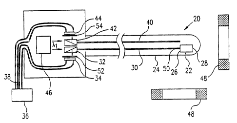
Reference is now made to Fig. 1A, which shows a
probe 24, preferably a catheter, including a magnetic-
field responsive position sensor 20, in accordance with
a preferred embodiment of the present invention. Sensor
20 comprises a magneto-optic crystal 22, preferably
yttrium iron garnet (YIG), and an optical fiber 30, in
this case a single-mode, polarization-preserving fiber.
In the preferred embodiment shown in Fig. 1A, crystal 22
has two opposing parallel faces, proximal face 26 and
distal face 28, orthogonal to a symmetry axis 50 of the
distal end of fiberoptic 30. Fiber 30 is connected to
face 26, preferably by optical cement. Face 28 is
preferably coated with a reflecting material, for
example, an aluminum or dielectric coating, as is known
in the art, so that light incident from the fiberoptic
onto the magneto-optic material and passing through face
26 is largely reflected from face 28 back to the
fiberoptic. In the presence of a magnetic field, the
plane of polarization of the reflected light will be
rotated by an angle proportional to the component of the
magnetic field parallel to axis 50.
As shown in Fig. 1A, probe 24 is placed in the
magnetic field of one, two, or more magnetic radiator
coils 48, the fields of said coils preferably having
been previously mapped and/or calibrated using methods
known in the art. Generally the magnetic field of the
radiator coils is a DC field, or an AC field, or a
combination of a DC and an AC field.
In the preferred embodiment shown in Fig. 1A,
polarized light having a wavelength X1, where X1 is
preferably of the order of 1 m, is injected from a
CA 02295409 2000-01-13
- 8 - -
source 46 into the proximal end of fiberoptic 30,
preferably via a beamsplitter 32. The light traverses
the fiberoptic to the distal end thereof and enters into
magneto-optic crystal 22. It is reflected from face 28
through the magneto-optic crystal and the fiberoptic,
back to beamsplitter 32. Beamsplitter 32 is constructed
so as to direct the reflected light onto a detector 34,
which measures the intensity of the reflected light. In
the preferred embodiment shown in Fig. 1A, detector 34
generally comprises a polarizing element 52. It will be
appreciated that the intensity of the reflected light
measured by the detector is dependent on the degree of
rotation of the plane of polarization caused by the
magneto-optic crystal 22.
Although the intensity of the reflected light is a
measure of the component of the magnetic field along
axis 50 at magneto-optic crystal 22, the intensity may
also be affected by temperature changes or mechanical
deformation in the fiberoptic. Therefore, a second
compensating fiberoptic 40, not coupled to the magneto-
optical material, is fixed in the probe in proximity to
fiberoptic 30, and light is injected into fiberoptic 40
as described above regarding fiberoptic 30. Light
reflected from the distal end of fiberoptic 40 passes
through beam splitter 42 and a polarizing element 54 to
detector 44. It will be appreciated that the intensity
of the reflected light measured by detector 44 is not
dependent on the magnetic field acting on the magneto-
optical material 22. Electrical signals from detectors
34 and 44 are fed by wires 38 to signal processing
circuitry 36, which processes the signals by difference
or other signal processing techniques known in the art
to determine the amplitude of the magnetic field at
CA 02295409 2007-09-26
9 - -
crystal 22. As described in U.S. patent 5,391,199; the
location of the sensor is derived from the amplitude of
the magnetic field.
Fig. 1B schematically illustrates another magneto-
optic position sensor 60, similarly suitable for use in
probe 24, in accordance with an alternative preferred
embodiment of the present invention. Apart from the
differences described below, the operation of position
sensor 60 is generally similar to that of position
sensor 20, whereby components with the same reference
numerals are generally identical in construction and
operation. In the preferred embodiment shown in Fig. 1B,
polarized light having a wavelength 7.1 and a reference
wavelength X2, where X2 is substantially different from
X1, is injected from a source 47 into the proximal end
of fiberoptic 30, preferably via first and second
dichroic beamsplitters 33 and 35. Beamsplitter 33 is
designed to substantially fully transmit X1 and to
deflect light at X2. Beamsplitter 35 is designed to
substantially fully transmit X2 and to deflect light at
x1. Beamsplitter 35 directs reflected light of
wavelength A.1 onto detector 34 via polarizer 52.
Beamsplitter 33 directs reflected light of wavelength X2
onto detector 44 via polarizer 54. A dichroic mirror 27,
which substantially transmits X1 and reflects X2, is
placed between the distal end of fiberoptic 30 and
proximal end 26 of crystal 22.
Thus, the intensity of the reflected light measured
by detector 34 is dependent on the degree of rotation of
the plane of polarization caused by the magneto-optic
crystal 22, while the intensity of the reflected light
measured by detector 44 is substantially independent of
CA 02295409 2000-01-13
-
the magnetic field acting on magneto-optical material
22. Both intensities are substantially equally affected
by temperature changes or mechanical deformation in the
fiberoptic, so that the signal from detector 44 may be
5 used as a compensating reference signal. As described
above regarding sensor 20, electrical signals from
detectors 34 and 44 are used to determine the amplitude
of the magnetic field at crystal 22, and the location of
the sensor is derived from the amplitude of the field.
10 Fig. 1C schematically illustrates yet another
magneto-optic position sensor 120, similarly suitable
for use in probe 24, in accordance with an alternative
preferred embodiment of the present invention. In sensor
120, a polarizer 56 is placed between the distal end of
fiberoptic 30 and proximal face 26 of magneto-optical
crystal 22. In this preferred embodiment, the light
injected into the fiberoptic by source 46 is generally
unpolarized, and fiberoptic 30 is not necessarily a
single mode or a polarization preserving fiberoptic.
Polarizer 56 thus acts as an analyzer of light reflected
from face 28. The light reflected passes to beam
splitter 32 and to detector 34, which generates
electrical signals used to determine the amplitude of
the magnetic field, as described above.
Although the preferred embodiments described above
measure only a single directional component of the
magnetic field, those skilled in the art will appreciate
that similar sensors may be produced for measuring two
or three components of the field, preferably by using a
plurality of magneto-optic crystals, each with a
respective fiberoptic and detector. The crystals are
oriented so that each respective crystal axis is aligned
along a different field axis. In a preferred embodiment
CA 02295409 2000-01-13
- 11 - -
of the present invention, not shown in the figures,
three such crystals, in mutually substantially
orthogonal orientations, may be used to measure six-
dimensional position and orientation coordinates of a
probe, using methods described in the above-mentioned
PCT publication W096/05768. In another preferred
embodiment, three separate fiberoptics are connected to
one magneto-optic crystal so as to inject into the
crystal and receive therefrom three mutually
substantially orthogonal beams of light, whereby the
six-dimensional position and orientation coordinates are
found.
In the preferred embodiments described above, the
magneto-optic polarization effect of crystal 22 may be
characterized by a hysteresis curve, as is shown
schematically in Fig. 2. Therefore, a given polarization
rotation may correspond to two different values of
magnetic field strength, depending on where on the
hysteresis curve the crystal is operating. Preferably,
signal processing circuitry 36 tracks changes of
polarization rotation in the light received by
detectors, so as to compensate and correct for
ambiguities due to hysteresis. Alternatively, a
combination of DC and AC fields may be applied to
magnetic radiator coils 48 in order to compensate for
hysteresis effects, by methods known in the art, in
crystal 22.
Fig. 3 schematically illustrates another position
sensor 78 within a probe 68, in accordance with an
alternative preferred embodiment of the present
invention. Sensor 78 comprises a fiberoptic 62
including a grating structure 64, preferably etched into
its outer surface or alternatively formed within the
CA 02295409 2007-09-26
12
core of the fiberoptic, using methods known in the art.
The fiberoptic is clad in the area of the grating with a
magnetostrictive cladding 66, preferably nickel. The
scale of the elements of sensor 78 is exaggerated in the
figure for clarity of illustration.
As described above, light of wavelength k1 is
injected into the proximal end of fiberoptic 62,
generally via a beam-splitter 72 from a light source 76,
which emits generally coherent light. The period of
grating 64 is preferably of the order of half the
wavelength X1 of the light injected. Magnetostrictive
cladding 66 expands or contracts as a function of the
external magnetic field component, parallel to grating
64, generated by magnetic radiator coils 48 thus
altering the grating period. Consequently the intensity
of the light at wavelength X1 reflected from grating 64
back to beam-splitter 72 and measured at detector 74 is
a function of the magnetic field component applied along
probe 68. Electrical signals from detector 74 are fed
to signal processing circuitry, as shown in Fig. 1A, and
the signals are processed to determine theamplitude of
the magnetic field at grating 64, and thus to determine
the position of probe 68.
Preferably, the magnetic field produced by coils 48
comprises an AC field, such that magnetostrictive
cladding 66 contracts and expands synchronously with the
field. The detection of signals from detector 74 is most
preferably locked to the frequency of the AC field, so
as to minimize interference due to spurious changes in
reflected light intensity caused by non-magnetostrictive
changes in fiberoptic parameters.
Fig. 4 schematically illustrates a set of position
sensors 80 within a probe 90, in accordance with a
CA 02295409 2005-06-13
13 - -
further preferred embodiment of the present invention.
Sensors 80 operate in conjunction with a,polychromatic
light source 94, preferably a laser, emitting a
plurality of substantially different coherent
wavelengths X1, X2, X3, and X4. The light is injected via
a broadband beamsplitter 88, or by other methods known
in the art, into the proximal end of a fiberoptic 82.
The fiberoptic comprises a plurality of gratings 84,
formed as described above, corresponding to the
plurality of injected wavelengths. Each of the gratings
84 has a substantially different grating period 92,
preferably equal to half of a respective one of the
plurality of wavelengths of the light injected. The
wavelengths X1, X2, 713, and X4 are selected so that each
grating generally reflects one of the wavelengths and
largely transmits the others.
Each of gratings 84 is separately clad by a
magnetostrictive cladding 86, which in the presence of a
magnetic field, applied by magnetic radiator coils 48,
alters the grating period as described above, and
consequently changes the intensity of the light
reflected from each grating. The reflected light is
transferred via beamsplitter 88 to a diffraction grating
96, or other suitable wavelength-dispersive element.
Grating 96 disperses the light according to wavelength
onto a detector 98, most preferably a linear array
detector, giving separate outputs for each of the
plurality of wavelengths. As described above, the
intensity of the light reflected from each of the
gratings 84 and measured at detector 98 is a function of
the magnetic field generated by the magnetic radiator
coils at the respective grating. Electrical signals from
detector 98 are fed to signal processing circuitry, as
CA 02295409 2000-01-13
14 - -
shown in Fig. 1A, and the signals are processed to
determine the amplitude of the magnetic field at each
grating. Thus, the respective positions of multiple
points along probe 90, corresponding to multiple
gratings 84, are determined.
Preferably the magnetic field in the preferred
embodiment comprises an AC field, such that the
magnetostrictive material contracts and expands
synchronously with the field. The detection of signals
from detector 98 is most preferably locked to the
frequency of the AC field, as described above.
Although the preferred embodiments described above
use reflection, from crystal 22 or gratings 64 or 84
back through the fiberoptic, to transfer the modulated
light from the sensors to the detectors, it will be
appreciated by those skilled in the art that other
optical configurations can also be used to accomplish
the transfer. Specifically, the modulated light from the
sensors can be transferred to the detectors using
transmission through the crystal or gratings.
It will be appreciated that the preferred
embodiments described above are cited by way of example,
and the full scope of the invention is limited only by
the claims.