Language selection

Search

Patent 2295668 Summary

Third-party information liability

Some of the information on this Web page has been provided by external sources. The Government of Canada is not responsible for the accuracy, reliability or currency of the information supplied by external sources. Users wishing to rely upon this information should consult directly with the source of the information. Content provided by external sources is not subject to official languages, privacy and accessibility requirements.

Claims and Abstract availability

Any discrepancies in the text and image of the Claims and Abstract are due to differing posting times. Text of the Claims and Abstract are posted:

  • At the time the application is open to public inspection;
  • At the time of issue of the patent (grant).
(12) Patent Application: (11) CA 2295668
(54) English Title: ELECTRIC INSTALLATION PROTECTING MEANS
(54) French Title: DISPOSITIF DE PROTECTION D'INSTALLATION ELECTRIQUE
Status: Deemed Abandoned and Beyond the Period of Reinstatement - Pending Response to Notice of Disregarded Communication
Bibliographic Data
Abstracts

English Abstract


A protective arrangement (10) for inclusion in an electric installation system
designed to prevent the cause of fire or damage to the installation due to the
sudden electrical failure or rise of temperature in the vicinity of the
system. A component short circuits between phase and zero or earth whenever
the temperature rises to a predetermined level.


French Abstract

La présente invention concerne un dispositif de protection (10), intégré au système de l'installation électrique, et conçu pour éviter que l'installation ne subisse un incendie, au tout autre sinistre, par suite d'une coupure électrique soudaine ou d'une élévation soudaine de la température au voisinage du système. A cet effet, un composant court-circuite la phase avec le neutre (ou la terre) dès que la température dépasse un certain niveau.

Claims

Note: Claims are shown in the official language in which they were submitted.

5
CLAIMS
1. A protective means for electric installation comprising as a component of
the
respective electric system a heat sensitive component.
2. A protective means as claimed in claim 1 characterized thereby that said
means
being a bi-metallic make and break switch.
3. A protective means as claimed in claim 1 characterized thereby that said
means
being a thermic fuse.
4. A protective means as claimed in claim 1 characterized thereby that said
means
being a thermic switch.
5. An electric installation system according to claim 1 wherein a wall socket
is
included the "earth", "zero" and "phase" terminals of which are connected to
two terminals of the protection means as claimed in claim 1.
6. An electric installation system according to claim 1 comprising a complex
socket or a complex plug two terminals thereof are respectively connected to
two terminals of the said means as claimed in claim 1.

Description

Note: Descriptions are shown in the official language in which they were submitted.


CA 02295668 2000-O1-06
WO 99/04474 PCT/IL9?/00244
ELECTRIC INSTALLATION PROTECTING MEANS
Field and Background of Invention
The present invention relates to a protective arrangement for inclusion in an
electric installation system, especially the new arrangement is designed to
prevent
the cause of fire or damage to the installation due to the sudden electrical
failure or
rise of temperature in the vicinity of the assembly of integers constituting
the
arrangement.
The existing protective means designed for inclusion in conventional electric
installations are targeted to prevent harm to humanity by electrification. The
conventional means do not consider at all the likelihood of damage to goods
and/or
premises caused by a short and likely thereby caused spark, or rise of
temperature.
The heating up of electric wires is a common phenomenon and the consequences
are well known and need no further elaboration.
The new protective arrangement construction is based on the recognition that
harm
could be prevented if, whenever the temperature rises within or at the
vicinity of
the new protective means, the new means would be actuated and disconnects the
whole circuit from the grid.
SUBSTITUTE SHEET {RULE 26)

CA 02295668 2000-O1-06
WO 99/04474 PCT/IL97/00244
2
Scope of Invention
This object, according to the invention is obtained by inclusion into a
constitutive
portion of the respective electric system, a new component which is assigned
to
short circuit between "phase" and "zero" or "earth" whenever the temperature
rises
to a predetermined level.
According to the invention the new arrangement, relates to component such as
bi-
metallic make and break or thermic fuse or switch and the like members of
generally known type destined for different purposes.
Such a device could be included e.g., into a wall socket by fixedly connecting
its
two terminals to the "earth" and "zero" or "zero" and "phase" or "phase and
earth"
etc., terminals of such a wall socket.
It is also within the scope of the invention to include said component or
device
within the electric plug.
As stated above a large number of components could be used for utilizing the
invention in the following description, reference is made by example to a bi-
metallic made and break device.
SUBSTITUTE.SHEET (RULE 26)

CA 02295668 2000-O1-06
WO 99/04474 PCT/IL97/00244
Short Description of Drawings
The invention will now be described in detail with reference to the
accompanying
drawings thereof:
Figure 1 is a schematic, perspective view of a conventional bi-metallic make -
and
break device.
Figure 2 being a frontal view thereof.
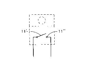
Figure 3 illustrates in a schematical manner the function of the device of
Figures
1 and 2.
Figure 4 illustrates diagramatically by way of example an electric
installation
comprising a socket in which the new means is inserted.
Description of Preferred Embodiment
Turning first to Figures 1 and 2 the generally know bi-metallic make and break
device comprises a box shaped casing 10 from which extend two terminal wires
11. As shown in Figure 3 the casing includes two terminals 11' and 11" of
metals
of different heat expansion coefficient. At normal flow of current terminals
11' and
11" are distant from each other, i.e. the contact if "open". At rise of
temperature in
whatever part of the system the terminals 11' and 11" snap towards each other
the
contact is closed.
SUBSTITUTE SHEET (RULE 26)

CA 02295668 2000-O1-06
WO 99/04474 PCT/IL97/00244
4
In the example of Figure 4 the outlay of an electric installation is shown,
comprising a main conduit 1 leading from the respective grid and feeding the
systems which includes a main switch 2, making or breaking contact via a
leakage
relay 3 with a consumer switch 4 and a consumer line 5 leading to an electric
implement, e.g. a wall socket 6. Into the latter is inserted the bi-metallic
component 7 of Figure 3 comprising the terminals 11' and 11 ". Terminals 11'
and
11 " are connected according to the example to the "earth" and "zero"
terminals of
wall socket 6 respectively.
At normal flow of current there is no contact between "earth" and "zero"
terminals
of sockets 6 in case - however - of a rise of temperature at socket 6 the bi-
metallic
implement 10 establishes a short circuit 11' - 11" actuation the leakage relay
3, i.e.,
the whole consumer installation, from the main line 1.
It is quite obvious that the device could be installed also between any other
two
terminals.
Those skilled in the art will see that in every system comprising a leakage
relay
intermediate a main line from the grid and a consumer line can be protected be
including the new means in whatever consumer outlet.
Whereas by way of examples of use of the new safety means has been described
in
connection with a wall socket, it is obvious that such a means could equally
be
included in different implement, e.g., coupler sockets (popularly also called
"receptacles") or coupler plugs, lamp housing, and the like.
SUBSTITUTE SHEET (RULE 26)

Representative Drawing
A single figure which represents the drawing illustrating the invention.
Administrative Status

2024-08-01:As part of the Next Generation Patents (NGP) transition, the Canadian Patents Database (CPD) now contains a more detailed Event History, which replicates the Event Log of our new back-office solution.

Please note that "Inactive:" events refers to events no longer in use in our new back-office solution.

For a clearer understanding of the status of the application/patent presented on this page, the site Disclaimer , as well as the definitions for Patent , Event History , Maintenance Fee  and Payment History  should be consulted.

Event History

Description Date
Inactive: IPC from MCD 2006-03-12
Application Not Reinstated by Deadline 2001-07-17
Time Limit for Reversal Expired 2001-07-17
Deemed Abandoned - Failure to Respond to Maintenance Fee Notice 2000-07-17
Inactive: Cover page published 2000-03-07
Inactive: IPC assigned 2000-03-03
Inactive: First IPC assigned 2000-03-03
Inactive: Notice - National entry - No RFE 2000-02-16
Application Received - PCT 2000-02-11
Application Published (Open to Public Inspection) 1999-01-28

Abandonment History

Abandonment Date Reason Reinstatement Date
2000-07-17

Maintenance Fee

The last payment was received on 2000-01-06

Note : If the full payment has not been received on or before the date indicated, a further fee may be required which may be one of the following

  • the reinstatement fee;
  • the late payment fee; or
  • additional fee to reverse deemed expiry.

Please refer to the CIPO Patent Fees web page to see all current fee amounts.

Fee History

Fee Type Anniversary Year Due Date Paid Date
MF (application, 2nd anniv.) - small 02 1999-07-19 2000-01-06
Basic national fee - small 2000-01-06
Owners on Record

Note: Records showing the ownership history in alphabetical order.

Current Owners on Record
ARAM DEKEL
Past Owners on Record
None
Past Owners that do not appear in the "Owners on Record" listing will appear in other documentation within the application.
Documents

To view selected files, please enter reCAPTCHA code :


To view images, click a link in the Document Description column. To download the documents, select one or more checkboxes in the first column and then click the "Download Selected in PDF format (Zip Archive)" or the "Download Selected as Single PDF" button.

List of published and non-published patent-specific documents on the CPD .

If you have any difficulty accessing content, you can call the Client Service Centre at 1-866-997-1936 or send them an e-mail at CIPO Client Service Centre.


Document
Description 
Date
(yyyy-mm-dd) 
Number of pages   Size of Image (KB) 
Cover Page 2000-03-07 1 28
Abstract 2000-01-06 1 31
Description 2000-01-06 4 124
Claims 2000-01-06 1 26
Drawings 2000-01-06 1 14
Representative drawing 2000-03-07 1 2
Notice of National Entry 2000-02-16 1 195
Courtesy - Abandonment Letter (Maintenance Fee) 2000-08-14 1 184
PCT 2000-01-06 8 283