Sélection de la langue

Search

Sommaire du brevet 2295668 

Énoncé de désistement de responsabilité concernant l'information provenant de tiers

Une partie des informations de ce site Web a été fournie par des sources externes. Le gouvernement du Canada n'assume aucune responsabilité concernant la précision, l'actualité ou la fiabilité des informations fournies par les sources externes. Les utilisateurs qui désirent employer cette information devraient consulter directement la source des informations. Le contenu fourni par les sources externes n'est pas assujetti aux exigences sur les langues officielles, la protection des renseignements personnels et l'accessibilité.

Disponibilité de l'Abrégé et des Revendications

L'apparition de différences dans le texte et l'image des Revendications et de l'Abrégé dépend du moment auquel le document est publié. Les textes des Revendications et de l'Abrégé sont affichés :

  • lorsque la demande peut être examinée par le public;
  • lorsque le brevet est émis (délivrance).
(12) Demande de brevet: (11) CA 2295668
(54) Titre français: DISPOSITIF DE PROTECTION D'INSTALLATION ELECTRIQUE
(54) Titre anglais: ELECTRIC INSTALLATION PROTECTING MEANS
Statut: Réputée abandonnée et au-delà du délai pour le rétablissement - en attente de la réponse à l’avis de communication rejetée
Données bibliographiques
Abrégés

Abrégé français

La présente invention concerne un dispositif de protection (10), intégré au système de l'installation électrique, et conçu pour éviter que l'installation ne subisse un incendie, au tout autre sinistre, par suite d'une coupure électrique soudaine ou d'une élévation soudaine de la température au voisinage du système. A cet effet, un composant court-circuite la phase avec le neutre (ou la terre) dès que la température dépasse un certain niveau.


Abrégé anglais


A protective arrangement (10) for inclusion in an electric installation system
designed to prevent the cause of fire or damage to the installation due to the
sudden electrical failure or rise of temperature in the vicinity of the
system. A component short circuits between phase and zero or earth whenever
the temperature rises to a predetermined level.

Revendications

Note : Les revendications sont présentées dans la langue officielle dans laquelle elles ont été soumises.


5
CLAIMS
1. A protective means for electric installation comprising as a component of
the
respective electric system a heat sensitive component.
2. A protective means as claimed in claim 1 characterized thereby that said
means
being a bi-metallic make and break switch.
3. A protective means as claimed in claim 1 characterized thereby that said
means
being a thermic fuse.
4. A protective means as claimed in claim 1 characterized thereby that said
means
being a thermic switch.
5. An electric installation system according to claim 1 wherein a wall socket
is
included the "earth", "zero" and "phase" terminals of which are connected to
two terminals of the protection means as claimed in claim 1.
6. An electric installation system according to claim 1 comprising a complex
socket or a complex plug two terminals thereof are respectively connected to
two terminals of the said means as claimed in claim 1.

Description

Note : Les descriptions sont présentées dans la langue officielle dans laquelle elles ont été soumises.

CA 02295668 2000-O1-06
WO 99/04474 PCT/IL9?/00244
ELECTRIC INSTALLATION PROTECTING MEANS
Field and Background of Invention
The present invention relates to a protective arrangement for inclusion in an
electric installation system, especially the new arrangement is designed to
prevent
the cause of fire or damage to the installation due to the sudden electrical
failure or
rise of temperature in the vicinity of the assembly of integers constituting
the
arrangement.
The existing protective means designed for inclusion in conventional electric
installations are targeted to prevent harm to humanity by electrification. The
conventional means do not consider at all the likelihood of damage to goods
and/or
premises caused by a short and likely thereby caused spark, or rise of
temperature.
The heating up of electric wires is a common phenomenon and the consequences
are well known and need no further elaboration.
The new protective arrangement construction is based on the recognition that
harm
could be prevented if, whenever the temperature rises within or at the
vicinity of
the new protective means, the new means would be actuated and disconnects the
whole circuit from the grid.
SUBSTITUTE SHEET {RULE 26)

CA 02295668 2000-O1-06
WO 99/04474 PCT/IL97/00244
2
Scope of Invention
This object, according to the invention is obtained by inclusion into a
constitutive
portion of the respective electric system, a new component which is assigned
to
short circuit between "phase" and "zero" or "earth" whenever the temperature
rises
to a predetermined level.
According to the invention the new arrangement, relates to component such as
bi-
metallic make and break or thermic fuse or switch and the like members of
generally known type destined for different purposes.
Such a device could be included e.g., into a wall socket by fixedly connecting
its
two terminals to the "earth" and "zero" or "zero" and "phase" or "phase and
earth"
etc., terminals of such a wall socket.
It is also within the scope of the invention to include said component or
device
within the electric plug.
As stated above a large number of components could be used for utilizing the
invention in the following description, reference is made by example to a bi-
metallic made and break device.
SUBSTITUTE.SHEET (RULE 26)

CA 02295668 2000-O1-06
WO 99/04474 PCT/IL97/00244
Short Description of Drawings
The invention will now be described in detail with reference to the
accompanying
drawings thereof:
Figure 1 is a schematic, perspective view of a conventional bi-metallic make -
and
break device.
Figure 2 being a frontal view thereof.
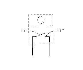
Figure 3 illustrates in a schematical manner the function of the device of
Figures
1 and 2.
Figure 4 illustrates diagramatically by way of example an electric
installation
comprising a socket in which the new means is inserted.
Description of Preferred Embodiment
Turning first to Figures 1 and 2 the generally know bi-metallic make and break
device comprises a box shaped casing 10 from which extend two terminal wires
11. As shown in Figure 3 the casing includes two terminals 11' and 11" of
metals
of different heat expansion coefficient. At normal flow of current terminals
11' and
11" are distant from each other, i.e. the contact if "open". At rise of
temperature in
whatever part of the system the terminals 11' and 11" snap towards each other
the
contact is closed.
SUBSTITUTE SHEET (RULE 26)

CA 02295668 2000-O1-06
WO 99/04474 PCT/IL97/00244
4
In the example of Figure 4 the outlay of an electric installation is shown,
comprising a main conduit 1 leading from the respective grid and feeding the
systems which includes a main switch 2, making or breaking contact via a
leakage
relay 3 with a consumer switch 4 and a consumer line 5 leading to an electric
implement, e.g. a wall socket 6. Into the latter is inserted the bi-metallic
component 7 of Figure 3 comprising the terminals 11' and 11 ". Terminals 11'
and
11 " are connected according to the example to the "earth" and "zero"
terminals of
wall socket 6 respectively.
At normal flow of current there is no contact between "earth" and "zero"
terminals
of sockets 6 in case - however - of a rise of temperature at socket 6 the bi-
metallic
implement 10 establishes a short circuit 11' - 11" actuation the leakage relay
3, i.e.,
the whole consumer installation, from the main line 1.
It is quite obvious that the device could be installed also between any other
two
terminals.
Those skilled in the art will see that in every system comprising a leakage
relay
intermediate a main line from the grid and a consumer line can be protected be
including the new means in whatever consumer outlet.
Whereas by way of examples of use of the new safety means has been described
in
connection with a wall socket, it is obvious that such a means could equally
be
included in different implement, e.g., coupler sockets (popularly also called
"receptacles") or coupler plugs, lamp housing, and the like.
SUBSTITUTE SHEET (RULE 26)

Dessin représentatif
Une figure unique qui représente un dessin illustrant l'invention.
États administratifs

2024-08-01 : Dans le cadre de la transition vers les Brevets de nouvelle génération (BNG), la base de données sur les brevets canadiens (BDBC) contient désormais un Historique d'événement plus détaillé, qui reproduit le Journal des événements de notre nouvelle solution interne.

Veuillez noter que les événements débutant par « Inactive : » se réfèrent à des événements qui ne sont plus utilisés dans notre nouvelle solution interne.

Pour une meilleure compréhension de l'état de la demande ou brevet qui figure sur cette page, la rubrique Mise en garde , et les descriptions de Brevet , Historique d'événement , Taxes périodiques et Historique des paiements devraient être consultées.

Historique d'événement

Description Date
Inactive : CIB de MCD 2006-03-12
Demande non rétablie avant l'échéance 2001-07-17
Le délai pour l'annulation est expiré 2001-07-17
Réputée abandonnée - omission de répondre à un avis sur les taxes pour le maintien en état 2000-07-17
Inactive : Page couverture publiée 2000-03-07
Inactive : CIB attribuée 2000-03-03
Inactive : CIB en 1re position 2000-03-03
Inactive : Notice - Entrée phase nat. - Pas de RE 2000-02-16
Demande reçue - PCT 2000-02-11
Demande publiée (accessible au public) 1999-01-28

Historique d'abandonnement

Date d'abandonnement Raison Date de rétablissement
2000-07-17

Taxes périodiques

Le dernier paiement a été reçu le 2000-01-06

Avis : Si le paiement en totalité n'a pas été reçu au plus tard à la date indiquée, une taxe supplémentaire peut être imposée, soit une des taxes suivantes :

  • taxe de rétablissement ;
  • taxe pour paiement en souffrance ; ou
  • taxe additionnelle pour le renversement d'une péremption réputée.

Veuillez vous référer à la page web des taxes sur les brevets de l'OPIC pour voir tous les montants actuels des taxes.

Historique des taxes

Type de taxes Anniversaire Échéance Date payée
TM (demande, 2e anniv.) - petite 02 1999-07-19 2000-01-06
Taxe nationale de base - petite 2000-01-06
Titulaires au dossier

Les titulaires actuels et antérieures au dossier sont affichés en ordre alphabétique.

Titulaires actuels au dossier
ARAM DEKEL
Titulaires antérieures au dossier
S.O.
Les propriétaires antérieurs qui ne figurent pas dans la liste des « Propriétaires au dossier » apparaîtront dans d'autres documents au dossier.
Documents

Pour visionner les fichiers sélectionnés, entrer le code reCAPTCHA :


Pour visualiser une image, cliquer sur un lien dans la colonne description du document. Pour télécharger l'image (les images), cliquer l'une ou plusieurs cases à cocher dans la première colonne et ensuite cliquer sur le bouton "Télécharger sélection en format PDF (archive Zip)" ou le bouton "Télécharger sélection (en un fichier PDF fusionné)".

Liste des documents de brevet publiés et non publiés sur la BDBC .

Si vous avez des difficultés à accéder au contenu, veuillez communiquer avec le Centre de services à la clientèle au 1-866-997-1936, ou envoyer un courriel au Centre de service à la clientèle de l'OPIC.


Description du
Document 
Date
(aaaa-mm-jj) 
Nombre de pages   Taille de l'image (Ko) 
Page couverture 2000-03-07 1 28
Abrégé 2000-01-06 1 31
Description 2000-01-06 4 124
Revendications 2000-01-06 1 26
Dessins 2000-01-06 1 14
Dessin représentatif 2000-03-07 1 2
Avis d'entree dans la phase nationale 2000-02-16 1 195
Courtoisie - Lettre d'abandon (taxe de maintien en état) 2000-08-14 1 184
PCT 2000-01-06 8 283