Language selection

Search

Patent 2295758 Summary

Third-party information liability

Some of the information on this Web page has been provided by external sources. The Government of Canada is not responsible for the accuracy, reliability or currency of the information supplied by external sources. Users wishing to rely upon this information should consult directly with the source of the information. Content provided by external sources is not subject to official languages, privacy and accessibility requirements.

Claims and Abstract availability

Any discrepancies in the text and image of the Claims and Abstract are due to differing posting times. Text of the Claims and Abstract are posted:

  • At the time the application is open to public inspection;
  • At the time of issue of the patent (grant).
(12) Patent Application: (11) CA 2295758
(54) English Title: GRINDING DEVICE FOR CHAIN SAWS
(54) French Title: DISPOSITIF D'AFFUTAGE DE SCIES A CHAINE
Status: Deemed Abandoned and Beyond the Period of Reinstatement - Pending Response to Notice of Disregarded Communication
Bibliographic Data
(51) International Patent Classification (IPC):
  • B23D 63/16 (2006.01)
(72) Inventors :
  • LOFGREN, PER-OLOF (Sweden)
(73) Owners :
  • KAPMAN AB
(71) Applicants :
  • KAPMAN AB (Sweden)
(74) Agent: GOWLING WLG (CANADA) LLP
(74) Associate agent:
(45) Issued:
(86) PCT Filing Date: 1998-06-17
(87) Open to Public Inspection: 1999-01-07
Availability of licence: N/A
Dedicated to the Public: N/A
(25) Language of filing: English

Patent Cooperation Treaty (PCT): Yes
(86) PCT Filing Number: PCT/SE1998/001176
(87) International Publication Number: SE1998001176
(85) National Entry: 1999-12-23

(30) Application Priority Data:
Application No. Country/Territory Date
9702479-8 (Sweden) 1997-06-27

Abstracts

English Abstract


Grinding device for chain saws, where the saw chain is sharpened b pressing an
abrasive block (15) against the top side of the cutter links (11) when the saw
chain is running around a rim type sprocket (14) and the generally cylindrical
periphery of the drive sprocket has raised steps or ramps (17, 27) which lift
the front end of the cutter links, thereby allowing a sufficiently large
cutting depth without locating the depth gauge far in front of the front
rivet. This reduces vibrations and instabilities of the saw chain when sawing.


French Abstract

L'invention concerne un dispositif d'affûtage de scies à chaîne. La chaîne est aiguisée par application d'un bloc abrasif (15) sur la face supérieure des maillons coupants (11) lorsque la chaîne défile autour d'une roue dentée de type jante (14). La périphérie généralement cylindrique de la roue d'entraînement possède des dents ou dents en biseau (17, 27) qui soulèvent l'extrémité frontale des maillons coupants (11). On obtient ainsi une profondeur de coupe suffisamment importante sans qu'il faille placer la cale étalon de profondeur loin devant le rivet frontal. Cela permet de réduire les vibrations et les instabilités de la chaîne lors du sciage.

Claims

Note: Claims are shown in the official language in which they were submitted.

6
Claims
1. Grinding device for chain saws, where cutter links (11) of a saw chain are
sharpened
by an abrasive block (15) which is pressed against the top side of the cutter
links while
the chain is running around a rim type drive sprocket (14), characterized by
the drive
sprocket having a generally cylindrical periphery with raised steps or ramps
(17,27)
which lift the front end of the cutter links higher than the rear end.
2. Device according to claim 1, characterized by having raised steps (17) of
equal height.
3. Device according to claim 1, characterized by having evenly sloping ramps
(27).

Description

Note: Descriptions are shown in the official language in which they were submitted.


CA 02295758 1999-12-23
WO 99/00211 PCT/SE98/01176
GR_TNDING DEVICE FOR CHAIN SAWS
Background
A majority of chain saws have chains, the cutter links of which have one
cutter and one
depth gauge for limiting the cutting depth and the risk of uncontrollable kick-
back and
impacts. These chains are sharpened by filing or grinding the front rake face
of the cutter.
Since the rear clearance face of the cutter has a certain small clearance
angle this will
lower the edge, requiring lowering also of the depth gauge by filing, which is
difficult to
do with sufficient precision.
Special chains have been previously suggested, designed for automatic
resharpening and
height adjustment of the depth gauge with high precision by grinding devices
without
removing the chain from the chain saw. According to the patents US 3,147,644,
US
3,502,122 and others, a grinding device has been located immediately behind
the drive
sprocket of the chain, and will grind both the cutter and the depth gauge
simultaneously
as the chain is running around the drive sprocket. Relative to the cutter
link, the grinding
device will follow a circular path, the highest point of which is located
where a radius
from the center of the drive sprocket center meets a line through the rivets
at 90 degrees
angle. With normal links and sprockets this occurs at the center of the links.
To keep the depth gauge as far lower than the cutter edge as corresponds to
the desired
cutting depth, the depth gauge must be located at a greater distance from of
this radius
than the cutter edge is, and to get a positive clearance angle the edge must
be located
behind the radius, as is shown by the patents US 3,147,644, US 3,170,497 and
others. For
hand-held chain saws a positive clearance angle is necessary since the
available feed
force is limited, which means that even with a small diameter of the drive
sprocket the
distance between the depth gauge and the cutter edge must be rather large.
This increases
the risk for kick-back and violent jerks when sawing thin branches or when a
tree moves.
Safety requirements have thus excluded such grinding devices from the market.

CA 02295758 1999-12-23
WO 99/00211 PCT/SE98/01176
7
For vehicle-born chain saws the problems are different.The drive sprocket
diameter must
be kept rather large to keep the motor velocity and the sprocket wear low. To
utilize the
motor power the cutting depth should be larger than with hand-held chain saws,
which
would require very long distance between the depth gauge and the cutter, in
actual cases
far in front of the front rivet, which in turn might cause severe vibrations
in service.
The present invention utilizes the non-existant risk of kick-back and the
availability of
higher mechanized feed force for vehicle-born chain saws, allowing smaller or
even
negative clearance angles. With a built-in grinding device according to the
invention, saw
chain with known and generally approved cutter links can be used.
Description
According to the invention, the chain saw is provided with a grinding device
immediately
behind the drive sprocket as is previously known. The drive sprocket, however,
is made
in such a way that the front rivet of a cutter link rides around it at a
greater diameter that
the rear rivet. The radius from the sprocket center which meets the line
through the rivets
at 90 degrees will then pass behind the center of the link, and the required
longer distance
from the depth gauge to the radius can be achieved with stable links, in
principle like
those described in US 3,170,497. The difference in diameter is chosen to make
the radius
pass close to the cutter edge. Should it pass behind the edge the clearance
angle will be
slightly negative, which is acceptable for vehicle-born chain saws. For such a
chain, all
sharpening is done with the built-in grinder.
The invention can also be used with traditional chain with L-shaped cutters.
These are
normally made with a hard chrome plated clearance face and are normally
sharpened by
filing of the non-plated rake face. The chrome layer is then l~~actured at
right angles to the
clearance face, which causes unnecessarily large cutting forces. Local
polishing or
whetting of the chrome layer after filing may make the clearance angle very
small or
slightly negative, but will still improve the durability and reduce the
cutting force.

CA 02295758 1999-12-23
WO 99/00211 PCT/SE98/01176
According to the invention the front end of the cutter link with the depth
gauge is raised,
when the grinding device acts as whetting the chrome layer. The part of the
chrome layer
which then becomes thinner is shorter than if the front end is not raised,
which improves
the durability. Whetting with a device according to the invention is
especially suitable for
cutter links with curved clearance face according to patents US 3,144,059 or
3,176,733,
where the whetted surface is mall even when repeated filing has moved the
cutter edge
close to the rear end of the cutter.
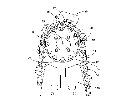
Figure 1 shows one preferred embodiment of the grinding device including a
drive
sprocket, and figure 2 an alternative form of the drive sprocket. Figure 3
shows how the
cutter link of a top sharpened chain according to prior art must have the
depth gauge very
far forward, figure 4 shows how a corresponding link according to the
invention may
have the depth gauge closer to the center to improve staability, figure 5
shows how the
invention can be used for whetting the cutter edge of a link with L-shaped
cutter after
filing.
Figure 1 shows a saw chain comprising drive links (13), cutter links (11) and
side links
(I2) without cutters. The saw chain runs around the edge of a guide bar (16)
and at the
rear end of the guide bar around a drive sprocket (14). Behind the drive
sprocket there is
an abrasive block ( 1 S) which can be pressed against the top surfaces of the
cutter links
( 11 ) to touch and grind the cutter edge as well as the depth gauge.
In grinding devices according to prior srt, the cutter links run with both
rivets at the same
distance from the drive sprocket center (21), and as shown in figure 3 the
radius (19) at
90 degrees to the line (20) throug the rivets will pass through the center of
the link. This
means that in order to grind the depth gauge (31) so much lower than the
cutter (32) that
corresponds to the desired chip thickness, the depth gauge (31 ) will have to
be located
very far forward, and the edge of the cutter (32) close to the radius (19) at
the center. If
the drive sprocket diameter is not very small, the depth gauge will have to be
located in
front of the front rivet as shown in US 3,170,497, causing vibrations and
instability when

CA 02295758 1999-12-23
WO 99/00211 PCT/SE98/01176
4
sawing. There is especially in vehicle-born chain saws a strong preference for
use of
large diameter drive sprockets, however.
According to the invention, the drive sprocket (14) is made as a rim sprocket
with two
side rims which support the cutterlinks (11) and sidelinks (12), and between
the rims
laterally open drive recesses ( 18) into which the drive links ( i 3) extend.
The drive
sprocket rims are made with raised steps ( 17) which keep the front end of the
cutter links
(11) uplifted during grinding, and the rest of the rims are cylindrical. If
the number of
drive recesses (18) is even, it is suitable to make one raised step (17) for
every second
recvess, and if the number os recesses is odd, there should be one raised step
for each
recess, since there is normally one cutter link (11) for every second drive
link (13). The
raised steps may have even height as in figure l, which makes the device less
sensitive to
wear and dimensional inaccuracy of the recesses, but causes concentrated point
loads on
the cutter links when grinding. The drive sprockets (24) can also be made with
evenly
sloping raised ramps (27) fully supporting the cutter links during the
grinding, and
cylindrical sections (28) between the ramps. The raised steps or ramps (17,27)
should be
made symmetrically on both side rims of the drive sprocket to support the
cutter link (11 )
as well as the side lint: joined to it with the rivets.
Since the front end of the cutter link is uplifted by the raised step or ramp
(17,27}, the
line (20) between the rivets will be sloping and the 90 degree radius (19)
will pass close
to th rear rivet, as shown in figure 4. This allows a more symmetric
positioning of the
cutter (42) and the depth gauge (41 ) relative to the rivets and the center of
the cutter link,
compared to what was shown in US 3,170,497, resulting in a stable motion of
the saw
chain even with greater cutting depth. This is especially valuable for saws
driven by
hydraulic motors, for which large diameter drive sprockets are desirable.
The cutter links shown in figures 3 and 4 have been of a type sharpened only
through
grinding of the clearance face on top of the cutter as described in US
3,170,497, where
the cutter edge is is insignificantly moved in a longitudinal direction by
repeated
grinding. Devices according to the invention can also be used with saw chains
with L-

CA 02295758 1999-12-23
WO 99/00211 PCT/SE98/01176
shaped cutters for whetting of the clearance face of the cutter edge between
or after
filings of the rake face. These saw chains have usually a thin hard chrome
layer on the
clearance face, and to avoid removing of too much of this layer when whetting,
the
clearance face should be sloping enough to let the whetting occur only at a
narrow zone
near the edge, and preferably be slightly curved as shown in US 3,176,733.

Representative Drawing
A single figure which represents the drawing illustrating the invention.
Administrative Status

2024-08-01:As part of the Next Generation Patents (NGP) transition, the Canadian Patents Database (CPD) now contains a more detailed Event History, which replicates the Event Log of our new back-office solution.

Please note that "Inactive:" events refers to events no longer in use in our new back-office solution.

For a clearer understanding of the status of the application/patent presented on this page, the site Disclaimer , as well as the definitions for Patent , Event History , Maintenance Fee  and Payment History  should be consulted.

Event History

Description Date
Application Not Reinstated by Deadline 2003-06-17
Time Limit for Reversal Expired 2003-06-17
Deemed Abandoned - Failure to Respond to Maintenance Fee Notice 2002-06-17
Inactive: Cover page published 2000-03-03
Inactive: First IPC assigned 2000-03-02
Letter Sent 2000-02-22
Inactive: Notice - National entry - No RFE 2000-02-17
Application Received - PCT 2000-02-11
Application Published (Open to Public Inspection) 1999-01-07

Abandonment History

Abandonment Date Reason Reinstatement Date
2002-06-17

Maintenance Fee

The last payment was received on 2001-06-18

Note : If the full payment has not been received on or before the date indicated, a further fee may be required which may be one of the following

  • the reinstatement fee;
  • the late payment fee; or
  • additional fee to reverse deemed expiry.

Patent fees are adjusted on the 1st of January every year. The amounts above are the current amounts if received by December 31 of the current year.
Please refer to the CIPO Patent Fees web page to see all current fee amounts.

Fee History

Fee Type Anniversary Year Due Date Paid Date
Registration of a document 1999-12-23
Basic national fee - standard 1999-12-23
MF (application, 2nd anniv.) - standard 02 2000-06-19 2000-05-25
MF (application, 3rd anniv.) - standard 03 2001-06-18 2001-06-18
Owners on Record

Note: Records showing the ownership history in alphabetical order.

Current Owners on Record
KAPMAN AB
Past Owners on Record
PER-OLOF LOFGREN
Past Owners that do not appear in the "Owners on Record" listing will appear in other documentation within the application.
Documents

To view selected files, please enter reCAPTCHA code :


To view images, click a link in the Document Description column. To download the documents, select one or more checkboxes in the first column and then click the "Download Selected in PDF format (Zip Archive)" or the "Download Selected as Single PDF" button.

List of published and non-published patent-specific documents on the CPD .

If you have any difficulty accessing content, you can call the Client Service Centre at 1-866-997-1936 or send them an e-mail at CIPO Client Service Centre.


Document
Description 
Date
(yyyy-mm-dd) 
Number of pages   Size of Image (KB) 
Representative drawing 2000-03-02 1 12
Abstract 1999-12-22 1 48
Description 1999-12-22 5 218
Drawings 1999-12-22 2 41
Claims 1999-12-22 1 17
Reminder of maintenance fee due 2000-02-21 1 113
Notice of National Entry 2000-02-16 1 195
Courtesy - Certificate of registration (related document(s)) 2000-02-21 1 115
Courtesy - Abandonment Letter (Maintenance Fee) 2002-07-14 1 183
Reminder - Request for Examination 2003-02-17 1 112
PCT 1999-12-22 8 297
Fees 2001-06-17 1 28
Fees 2008-07-02 1 41