Sélection de la langue

Search

Sommaire du brevet 2295758 

Énoncé de désistement de responsabilité concernant l'information provenant de tiers

Une partie des informations de ce site Web a été fournie par des sources externes. Le gouvernement du Canada n'assume aucune responsabilité concernant la précision, l'actualité ou la fiabilité des informations fournies par les sources externes. Les utilisateurs qui désirent employer cette information devraient consulter directement la source des informations. Le contenu fourni par les sources externes n'est pas assujetti aux exigences sur les langues officielles, la protection des renseignements personnels et l'accessibilité.

Disponibilité de l'Abrégé et des Revendications

L'apparition de différences dans le texte et l'image des Revendications et de l'Abrégé dépend du moment auquel le document est publié. Les textes des Revendications et de l'Abrégé sont affichés :

  • lorsque la demande peut être examinée par le public;
  • lorsque le brevet est émis (délivrance).
(12) Demande de brevet: (11) CA 2295758
(54) Titre français: DISPOSITIF D'AFFUTAGE DE SCIES A CHAINE
(54) Titre anglais: GRINDING DEVICE FOR CHAIN SAWS
Statut: Réputée abandonnée et au-delà du délai pour le rétablissement - en attente de la réponse à l’avis de communication rejetée
Données bibliographiques
Abrégés

Abrégé français

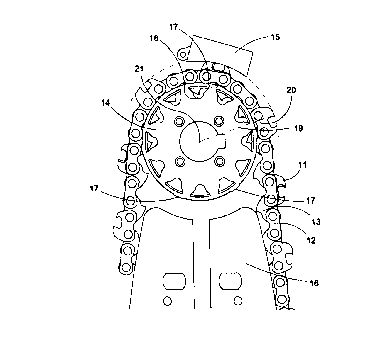
L'invention concerne un dispositif d'affûtage de scies à chaîne. La chaîne est aiguisée par application d'un bloc abrasif (15) sur la face supérieure des maillons coupants (11) lorsque la chaîne défile autour d'une roue dentée de type jante (14). La périphérie généralement cylindrique de la roue d'entraînement possède des dents ou dents en biseau (17, 27) qui soulèvent l'extrémité frontale des maillons coupants (11). On obtient ainsi une profondeur de coupe suffisamment importante sans qu'il faille placer la cale étalon de profondeur loin devant le rivet frontal. Cela permet de réduire les vibrations et les instabilités de la chaîne lors du sciage.


Abrégé anglais


Grinding device for chain saws, where the saw chain is sharpened b pressing an
abrasive block (15) against the top side of the cutter links (11) when the saw
chain is running around a rim type sprocket (14) and the generally cylindrical
periphery of the drive sprocket has raised steps or ramps (17, 27) which lift
the front end of the cutter links, thereby allowing a sufficiently large
cutting depth without locating the depth gauge far in front of the front
rivet. This reduces vibrations and instabilities of the saw chain when sawing.

Revendications

Note : Les revendications sont présentées dans la langue officielle dans laquelle elles ont été soumises.


6
Claims
1. Grinding device for chain saws, where cutter links (11) of a saw chain are
sharpened
by an abrasive block (15) which is pressed against the top side of the cutter
links while
the chain is running around a rim type drive sprocket (14), characterized by
the drive
sprocket having a generally cylindrical periphery with raised steps or ramps
(17,27)
which lift the front end of the cutter links higher than the rear end.
2. Device according to claim 1, characterized by having raised steps (17) of
equal height.
3. Device according to claim 1, characterized by having evenly sloping ramps
(27).

Description

Note : Les descriptions sont présentées dans la langue officielle dans laquelle elles ont été soumises.


CA 02295758 1999-12-23
WO 99/00211 PCT/SE98/01176
GR_TNDING DEVICE FOR CHAIN SAWS
Background
A majority of chain saws have chains, the cutter links of which have one
cutter and one
depth gauge for limiting the cutting depth and the risk of uncontrollable kick-
back and
impacts. These chains are sharpened by filing or grinding the front rake face
of the cutter.
Since the rear clearance face of the cutter has a certain small clearance
angle this will
lower the edge, requiring lowering also of the depth gauge by filing, which is
difficult to
do with sufficient precision.
Special chains have been previously suggested, designed for automatic
resharpening and
height adjustment of the depth gauge with high precision by grinding devices
without
removing the chain from the chain saw. According to the patents US 3,147,644,
US
3,502,122 and others, a grinding device has been located immediately behind
the drive
sprocket of the chain, and will grind both the cutter and the depth gauge
simultaneously
as the chain is running around the drive sprocket. Relative to the cutter
link, the grinding
device will follow a circular path, the highest point of which is located
where a radius
from the center of the drive sprocket center meets a line through the rivets
at 90 degrees
angle. With normal links and sprockets this occurs at the center of the links.
To keep the depth gauge as far lower than the cutter edge as corresponds to
the desired
cutting depth, the depth gauge must be located at a greater distance from of
this radius
than the cutter edge is, and to get a positive clearance angle the edge must
be located
behind the radius, as is shown by the patents US 3,147,644, US 3,170,497 and
others. For
hand-held chain saws a positive clearance angle is necessary since the
available feed
force is limited, which means that even with a small diameter of the drive
sprocket the
distance between the depth gauge and the cutter edge must be rather large.
This increases
the risk for kick-back and violent jerks when sawing thin branches or when a
tree moves.
Safety requirements have thus excluded such grinding devices from the market.

CA 02295758 1999-12-23
WO 99/00211 PCT/SE98/01176
7
For vehicle-born chain saws the problems are different.The drive sprocket
diameter must
be kept rather large to keep the motor velocity and the sprocket wear low. To
utilize the
motor power the cutting depth should be larger than with hand-held chain saws,
which
would require very long distance between the depth gauge and the cutter, in
actual cases
far in front of the front rivet, which in turn might cause severe vibrations
in service.
The present invention utilizes the non-existant risk of kick-back and the
availability of
higher mechanized feed force for vehicle-born chain saws, allowing smaller or
even
negative clearance angles. With a built-in grinding device according to the
invention, saw
chain with known and generally approved cutter links can be used.
Description
According to the invention, the chain saw is provided with a grinding device
immediately
behind the drive sprocket as is previously known. The drive sprocket, however,
is made
in such a way that the front rivet of a cutter link rides around it at a
greater diameter that
the rear rivet. The radius from the sprocket center which meets the line
through the rivets
at 90 degrees will then pass behind the center of the link, and the required
longer distance
from the depth gauge to the radius can be achieved with stable links, in
principle like
those described in US 3,170,497. The difference in diameter is chosen to make
the radius
pass close to the cutter edge. Should it pass behind the edge the clearance
angle will be
slightly negative, which is acceptable for vehicle-born chain saws. For such a
chain, all
sharpening is done with the built-in grinder.
The invention can also be used with traditional chain with L-shaped cutters.
These are
normally made with a hard chrome plated clearance face and are normally
sharpened by
filing of the non-plated rake face. The chrome layer is then l~~actured at
right angles to the
clearance face, which causes unnecessarily large cutting forces. Local
polishing or
whetting of the chrome layer after filing may make the clearance angle very
small or
slightly negative, but will still improve the durability and reduce the
cutting force.

CA 02295758 1999-12-23
WO 99/00211 PCT/SE98/01176
According to the invention the front end of the cutter link with the depth
gauge is raised,
when the grinding device acts as whetting the chrome layer. The part of the
chrome layer
which then becomes thinner is shorter than if the front end is not raised,
which improves
the durability. Whetting with a device according to the invention is
especially suitable for
cutter links with curved clearance face according to patents US 3,144,059 or
3,176,733,
where the whetted surface is mall even when repeated filing has moved the
cutter edge
close to the rear end of the cutter.
Figure 1 shows one preferred embodiment of the grinding device including a
drive
sprocket, and figure 2 an alternative form of the drive sprocket. Figure 3
shows how the
cutter link of a top sharpened chain according to prior art must have the
depth gauge very
far forward, figure 4 shows how a corresponding link according to the
invention may
have the depth gauge closer to the center to improve staability, figure 5
shows how the
invention can be used for whetting the cutter edge of a link with L-shaped
cutter after
filing.
Figure 1 shows a saw chain comprising drive links (13), cutter links (11) and
side links
(I2) without cutters. The saw chain runs around the edge of a guide bar (16)
and at the
rear end of the guide bar around a drive sprocket (14). Behind the drive
sprocket there is
an abrasive block ( 1 S) which can be pressed against the top surfaces of the
cutter links
( 11 ) to touch and grind the cutter edge as well as the depth gauge.
In grinding devices according to prior srt, the cutter links run with both
rivets at the same
distance from the drive sprocket center (21), and as shown in figure 3 the
radius (19) at
90 degrees to the line (20) throug the rivets will pass through the center of
the link. This
means that in order to grind the depth gauge (31) so much lower than the
cutter (32) that
corresponds to the desired chip thickness, the depth gauge (31 ) will have to
be located
very far forward, and the edge of the cutter (32) close to the radius (19) at
the center. If
the drive sprocket diameter is not very small, the depth gauge will have to be
located in
front of the front rivet as shown in US 3,170,497, causing vibrations and
instability when

CA 02295758 1999-12-23
WO 99/00211 PCT/SE98/01176
4
sawing. There is especially in vehicle-born chain saws a strong preference for
use of
large diameter drive sprockets, however.
According to the invention, the drive sprocket (14) is made as a rim sprocket
with two
side rims which support the cutterlinks (11) and sidelinks (12), and between
the rims
laterally open drive recesses ( 18) into which the drive links ( i 3) extend.
The drive
sprocket rims are made with raised steps ( 17) which keep the front end of the
cutter links
(11) uplifted during grinding, and the rest of the rims are cylindrical. If
the number of
drive recesses (18) is even, it is suitable to make one raised step (17) for
every second
recvess, and if the number os recesses is odd, there should be one raised step
for each
recess, since there is normally one cutter link (11) for every second drive
link (13). The
raised steps may have even height as in figure l, which makes the device less
sensitive to
wear and dimensional inaccuracy of the recesses, but causes concentrated point
loads on
the cutter links when grinding. The drive sprockets (24) can also be made with
evenly
sloping raised ramps (27) fully supporting the cutter links during the
grinding, and
cylindrical sections (28) between the ramps. The raised steps or ramps (17,27)
should be
made symmetrically on both side rims of the drive sprocket to support the
cutter link (11 )
as well as the side lint: joined to it with the rivets.
Since the front end of the cutter link is uplifted by the raised step or ramp
(17,27}, the
line (20) between the rivets will be sloping and the 90 degree radius (19)
will pass close
to th rear rivet, as shown in figure 4. This allows a more symmetric
positioning of the
cutter (42) and the depth gauge (41 ) relative to the rivets and the center of
the cutter link,
compared to what was shown in US 3,170,497, resulting in a stable motion of
the saw
chain even with greater cutting depth. This is especially valuable for saws
driven by
hydraulic motors, for which large diameter drive sprockets are desirable.
The cutter links shown in figures 3 and 4 have been of a type sharpened only
through
grinding of the clearance face on top of the cutter as described in US
3,170,497, where
the cutter edge is is insignificantly moved in a longitudinal direction by
repeated
grinding. Devices according to the invention can also be used with saw chains
with L-

CA 02295758 1999-12-23
WO 99/00211 PCT/SE98/01176
shaped cutters for whetting of the clearance face of the cutter edge between
or after
filings of the rake face. These saw chains have usually a thin hard chrome
layer on the
clearance face, and to avoid removing of too much of this layer when whetting,
the
clearance face should be sloping enough to let the whetting occur only at a
narrow zone
near the edge, and preferably be slightly curved as shown in US 3,176,733.

Dessin représentatif
Une figure unique qui représente un dessin illustrant l'invention.
États administratifs

2024-08-01 : Dans le cadre de la transition vers les Brevets de nouvelle génération (BNG), la base de données sur les brevets canadiens (BDBC) contient désormais un Historique d'événement plus détaillé, qui reproduit le Journal des événements de notre nouvelle solution interne.

Veuillez noter que les événements débutant par « Inactive : » se réfèrent à des événements qui ne sont plus utilisés dans notre nouvelle solution interne.

Pour une meilleure compréhension de l'état de la demande ou brevet qui figure sur cette page, la rubrique Mise en garde , et les descriptions de Brevet , Historique d'événement , Taxes périodiques et Historique des paiements devraient être consultées.

Historique d'événement

Description Date
Demande non rétablie avant l'échéance 2003-06-17
Le délai pour l'annulation est expiré 2003-06-17
Réputée abandonnée - omission de répondre à un avis sur les taxes pour le maintien en état 2002-06-17
Inactive : Page couverture publiée 2000-03-03
Inactive : CIB en 1re position 2000-03-02
Lettre envoyée 2000-02-22
Inactive : Notice - Entrée phase nat. - Pas de RE 2000-02-17
Demande reçue - PCT 2000-02-11
Demande publiée (accessible au public) 1999-01-07

Historique d'abandonnement

Date d'abandonnement Raison Date de rétablissement
2002-06-17

Taxes périodiques

Le dernier paiement a été reçu le 2001-06-18

Avis : Si le paiement en totalité n'a pas été reçu au plus tard à la date indiquée, une taxe supplémentaire peut être imposée, soit une des taxes suivantes :

  • taxe de rétablissement ;
  • taxe pour paiement en souffrance ; ou
  • taxe additionnelle pour le renversement d'une péremption réputée.

Les taxes sur les brevets sont ajustées au 1er janvier de chaque année. Les montants ci-dessus sont les montants actuels s'ils sont reçus au plus tard le 31 décembre de l'année en cours.
Veuillez vous référer à la page web des taxes sur les brevets de l'OPIC pour voir tous les montants actuels des taxes.

Historique des taxes

Type de taxes Anniversaire Échéance Date payée
Enregistrement d'un document 1999-12-23
Taxe nationale de base - générale 1999-12-23
TM (demande, 2e anniv.) - générale 02 2000-06-19 2000-05-25
TM (demande, 3e anniv.) - générale 03 2001-06-18 2001-06-18
Titulaires au dossier

Les titulaires actuels et antérieures au dossier sont affichés en ordre alphabétique.

Titulaires actuels au dossier
KAPMAN AB
Titulaires antérieures au dossier
PER-OLOF LOFGREN
Les propriétaires antérieurs qui ne figurent pas dans la liste des « Propriétaires au dossier » apparaîtront dans d'autres documents au dossier.
Documents

Pour visionner les fichiers sélectionnés, entrer le code reCAPTCHA :


Pour visualiser une image, cliquer sur un lien dans la colonne description du document. Pour télécharger l'image (les images), cliquer l'une ou plusieurs cases à cocher dans la première colonne et ensuite cliquer sur le bouton "Télécharger sélection en format PDF (archive Zip)" ou le bouton "Télécharger sélection (en un fichier PDF fusionné)".

Liste des documents de brevet publiés et non publiés sur la BDBC .

Si vous avez des difficultés à accéder au contenu, veuillez communiquer avec le Centre de services à la clientèle au 1-866-997-1936, ou envoyer un courriel au Centre de service à la clientèle de l'OPIC.


Description du
Document 
Date
(aaaa-mm-jj) 
Nombre de pages   Taille de l'image (Ko) 
Dessin représentatif 2000-03-02 1 12
Abrégé 1999-12-22 1 48
Description 1999-12-22 5 218
Dessins 1999-12-22 2 41
Revendications 1999-12-22 1 17
Rappel de taxe de maintien due 2000-02-21 1 113
Avis d'entree dans la phase nationale 2000-02-16 1 195
Courtoisie - Certificat d'enregistrement (document(s) connexe(s)) 2000-02-21 1 115
Courtoisie - Lettre d'abandon (taxe de maintien en état) 2002-07-14 1 183
Rappel - requête d'examen 2003-02-17 1 112
PCT 1999-12-22 8 297
Taxes 2001-06-17 1 28
Taxes 2008-07-02 1 41