Note: Descriptions are shown in the official language in which they were submitted.
SJ-10707CA
CA 02296219 2000-O1-18
- 1 -
TITLE~ MOUNTING ASSEMBLY OF A WINDOW TO A SURROUNDING
STRUCTURE
FIELD OF THE INVENTION
The present invention relates to a windowed
construction in which a window assembly is secured by
framing to a surrounding wall or door support for the
window assembly.
;BACKGROUND OF THE INVENTION ,
In laboratories, hospitals and similar environments
it is necessary to have, what is referred to as clean
rooms. These are rooms where it is very important to
15.' eliminate as much as possible dirt and debris that could
cause bacteria growth producing contamination of the clean
room. ,
One area of a clean room that is particularly
susceptible to cleaning problems is at the windows whether
they be in the wall or the door of the room. It is
important that there be minimal profile discrepancies
between the actual glazing of the widow and the
surrounding structure including the frame to simplify
cleaning of the window. To date, conventional window
constructions do not meet this requirement and therefore
are not particularly suitable for use in a clean room
environment.
SUMMARY OF THE PRESENT INVENTION
The present invention provides a windowed
construction which is well suited to a clean room
environment. This windowed construction comprises a window
assembly, a surrounding support structure for the window
assembly, i.e, the supporting wall or door and plastic
framing securing the window assembly to the supporting
CA 02296219 2000-O1-18
SJ-10707CA
- 2 -
structure.
The window assembly itself comprises a sealed
glazing unit formed by exterior shatterproof glass panels
with an interior glass filler.
The glazing unit and the surrounding supporting
structure are at least substantially'uniform in thickness
and the plastic framing comprises first and second frame
members presenting low profile glazing beads to opposite
sides of the window assembly thereby giving the
construction a generally flattened transition surface from
the glazing unit across the framing to the surrounding
support structure. '
The generally flattened transition surface of the
windowed construction of the present invention makes it
easily cleanable and therefore well suited for a clean room
environment.
BRIEF DESCRIPTION OF THE DRAWINGS
The above as well as other advantages and features
of the present invention will be described in greater
detail according to the preferred embodiments of the
present invention in which; '
Figure 1 is a perspective view of a windowed
construction according to a preferred embodiment of the
present invention;
Figure 2 is a sectional view through the transition
region from the glazing unit across the framing to the
supporting structure of the windowed'construction of Figure
1;
Figures 3 and 4 are sectional views through the
framing components used in the framing of the windowed
construction shown in Figure 2 of the drawings.
I . . ... Llil I
CA 02296219 2000-O1-18
SJ-10707CA
- 3 -
DETAILED DESCRIPTION ACCORDING TO THE PREFERRED EMBODIMENTS
OF THE PRESENT INVENTION IN WHICH:
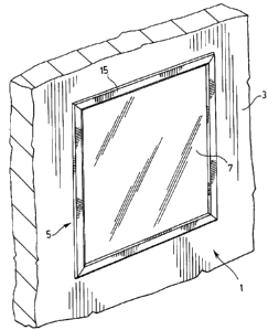
Figure 1 shows a windowed construction generally
indicated at 1. This windowed construction comprises a
window assembly generally indicated at 5 held by a
surrounding supporting structure 3. The surrounding
supporting structure could either be a wall or a door.
The window assembly itself includes glazing 7 which
in this case is a sealed glazing unit to be described later
in detail and which is secured with the surrounding
supporting structure by means of framing 15.
The framing has a plastic construction, e.g. a
vinyl material or the like which does not degrade over time
with washing as would be the case with, for example, a
metallic material.
Glazing unit 7, which is better shown in Figure 2
of the drawings comprises a pair of exterior shatterproof
glass panels 9 centered by a glass filler 11 which
typically is a panel of standard glass material. Filler 11
is protected by the shatterproof panels 9.
The entire window assembly is held together by a
perimeter piece 13 which secures all, of the panels together
as a sealed unit.
It is to be noted in Figure 2 that the sealed
glazing unit 7 is identical, or at least substantially
identical, in thickness to supporting structure 3.
Accordingly, there are no profile variances whatsoever in
the construction between these two components.
I i nn
CA 02296219 2000-O1-18
,. ~ SJ-10707CA
- 4 -
The plastic framing 15 used to secure the glazing
unit with the surrounding structure has, as also seen in
Figure 2, a very low profile which gives the overall
construction a generally flattened transition surface from
the glazing unit across the framing to the surrounding
supporting structure.
The actual componentry of the framing is better
described having reference to Figures 3 and 4 of the
drawings. In these figures, it will be seen that the
framing comprises first and second frame members generally
indicated at 17 and 41 respectively.
Framing member 17 consists of an elongated body
portion 19 which fits between the glazing unit and the
surrounding structure. This body portion terminates with a
pair of spaced apart legs 21 which define a cavity 23.
Aligned centrally with that cavity is a screw port 25.
Frame member 17 has a head which provides an
exterior glazing bead portion comprising a main center
region formed by a flat wall surface 27. A pair of short
flat arms 29 slope outwardly at a shallow angle relative to
wall surface 27. Preferably, arms 29 are set at a 45' or
lower degree angle relative to the flat wall surface 27
which when the construction is completed lies parallel to
both the glazing unit and the supporting structure.
Angled arms 29 of the two glazing bead portions
lying against the glazing unit and the supporting structure
are provided on their interior surfaces with flexible seals
31. These flexible seals are preferably co-extruded with
the framing member.
Arms 29 having outer ends 33 which are cut away to
leave a small gap 35 between the arms 29 and the glazing
CA 02296219 2000-O1-18
SJ-10707CA
- 5 -
unit and the supporting structure to each side of the frame
member. The provision of this small gap enables caulking
material to be inserted directly beneath the ends 33 of
arms 29.
Framing member 41, which is the framing member
which would be located to the inside of a room, has a small
male projection 43 which locates within the cavity 23 of
framing member 17 when the two framipg members are
assembled with one another as shown in Figure 2 of the
drawings. A small cut out 45 is provided in wall 46 of
framing member 41 to provide a centering location for a
screw used to secure the two frame members to opposite
sides of the window construction as is again shown in
Figure 2. This screw is centered by,and bites through cut
out 45, through the bottom wall of male member 43 and into
the screw port 25 of frame member 17. The head of the
screw locates against interior wall 46 of frame member 41
to hold the two frame members with one another.
Frame member 41, like frame member 47, has an
exterior head presenting glazing beads to its opposite
sides. This exterior head comprises a center portion
defined by flat walls 49 interrupted by a central opening
47 for the screw insertion into the frame member. A pair
of sloped arms 51 are located to the outer sides of flat
walls 49 and again these sloped legs, are set at a shallow,
e.g. 45 or lower degree angle relative to walls 49.
Each of the legs 51 is provided on its interior
surface with a soft flexible seal 53 and the ends 57 of the
legs are cut away to provide caulking receiving regions 61
at both the supporting structure 3 arid the glazing unit 7
to opposite sides of frame member 41.
After the two frame members 17 and 41 have been
imi
CA 02296219 2000-O1-18
. SJ-10707CA
- 6 -
secured by the screw to hold the entire construction
together, frame member 41 is completed with a cap 63
covering the center opening 47 of the framing member. This
cap, like the glazing bead head portion of the framing
member has a low profile to maintain the generally
flattened transition surface across the entire
construction.
As will be appreciated from the description above,
the windowed construction including the features of common
thickness, between the supporting structure and glazing
unit and low profile framing members; essentially
eliminates catch areas for bacteria producing dirt and
debris and presents an easily cleanable surface area.
Accordingly, the window construction of the present is
particularly well suited for a clean room environment.
Although various preferred embodiments of the
present invention have been described in detail, it will be
appreciated by those skilled in the art that variations may
be made without departing from the spirit of the invention
or the scope of the appended claims.