Note: Descriptions are shown in the official language in which they were submitted.
CA 02296340 2000-O1-14
-1-
Industrial Lift Truck
Description
The invention relates to an industrial lift truck with a load lifting device
and
a device for moving the load lifting device on the lift truck having at least
one
element that can move, together with the load lifting device, along an
essentially
straight guide, and with a position measuring device for monitoring the
position
relative to the guide of the load lifting device or of the element movable
with the
load lifting device.
Industrial lift trucks with a position measuring device for determining the
to position of the load lifting device relative to a reference point on the
lift truck in
question are known.
For instance, DE 195 08 346 Cl discloses an industrial lift truck with a
position measuring device for determining the lift height of an adjustable-
height
load lifting device. The load lifting device is driven by a hydraulic cylinder
15 supplied by a hydraulic pump, where the hydraulic pump is driven by an
electric
motor. Starting from an initial position of the load lifting device, the
rotations of
the hydraulic pump are counted up in one direction of rotation, and down in
the
opposite direction of rotation, and are evaluated in light of the overall
efficiency of
the lift system to determine the current lift height.
2o Moreover, with regard to industrial lift trucks, there has already been
proposed the concept of providing the lifting frame for a load lifting device
with
proximity switches at predetermined intervals which respond to a marking that
is
movable with the load lifting device in order to determine the current lift
height of
the load lifting device.
25 Known from DE 32 11 486 A1 is a forklift vehicle with the features
mentioned at the outset, wherein the position measuring device includes a
rotating
disk with radial slits on its edge that is arranged on the shaft of a pinion
that is
provided in the upper region of the moving part of the lift mast to deflect a
lift
NY02:238341.1
CA 02296340 2000-O1-14
-2-
chain for the load carrying fork. An optical sensor arrangement with a light-
emitting diode and a phototransistor is provided in the vicinity of the edge
of the
disk to measure the rotational motion of the disk. As the disk rotates, the
light path
formed by the light-emitting diode and the phototransistor is alternately
unblocked
by the edge slits and blocked by the teeth between the edge slits, so that the
phototransistor delivers a pulsed electrical signal whose pulse count at any
point
corresponds to the angle of rotation of the disk and that of the chain
sprocket that is
rotationally fixed to the disk, wherein the current change in lift height of
the load
carrying fork is determined from the angle of rotation of the chain sprocket
that is
to ' engaged with the lift chain. Since the rotation of the chain sprocket
when the load
carrying fork is raised or lowered is determined by the length of the section
of
chain that passes over the chain sprocket, changes in the chain length such as
those
which frequently occur during operation under load will lead to errors in
determining lift height. A further disadvantage of this known solution is that
the
15 sensor components (light-emitting diode, phototransistor, rotating disk)
must be
arranged on the moving part of the lift mast, since the chain sprocket
attached to
the rotating disk must be arranged on the moving lift mast section for
functional
reasons. This not only produces a design constraint, but also invariably
brings with
it the problems that arise when electrical signals are transmitted by moving
20 sensors.
The object of the invention is to specify an industrial lift truck of the type
described at the outset wherein the position measuring device can be realized
with
simple means, and thus economically, while reliably providing position
measurement results with high precision and resolution.
25 To achieve this object using an industrial lift truck with the features of
the
preamble to claim 1 as a basis, it is proposed in accordance with the
invention that
the position measuring device include at least one roller body that either a)
is
arranged on the element that is movable with the load lifting device such that
it is
capable of rotation and its circumference contacts a path running along the
guide in
3o such a way that it is forced to roll along the path by movement of the
element that
NY02:238341.1
CA 02296340 2000-O1-14
-3-
is movable with the load lifting device, or b) is arranged on an element that
is
stationary relative to the guide such that it is capable of rotation and its
circumference contacts the element that is movable with the load lifting
device in
such a way that it is forced to rotate by movement of the element that is
movable
with the load lifting device, and that the roller body act in combination with
a
sensor which transmits an electric signal as a function of the rotational
movement
of the roller body to an analysis circuit which evaluates the signal for
determining
the position of the element that is movable with the load lifting device or
the
position of the load carrier relative to the guide.
' In an industrial lift truck in the form of a lift truck, the load lifting
device is
usually a load carrying fork that is arranged on a fork carrier and is
vertically
movable, together with the fork Garner, on a lifting frame or mast. For
measuring
the lift height of the load carrying fork, in accordance with alternative a)
the roller
body is arranged on the fork carrier or an element attached thereto for
movement
along the guide in such a manner that, for instance, it rolls along a path on
the
lifting frame that is parallel to the direction of lift. The rotational
movement of the
roller body is measured by the sensor so that the analysis circuit connected
to the
sensor can evaluate the electrical signal for determining the lift height
supplied by
the sensor.
On the other hand, the roller body can be arranged in accordance with
alternative b), on an element that is stationary relative to the guide, where
its
circumference contacts the element that is movable with the load lifting
device in
such a way that it is forced to rotate by movement of the element that is
movable
with the load lifting device. Alternative b) has the advantage that the signal
lines
need not move, and can thus be laid in a fixed position.
The sensor is preferably a digital angular position sensor that is designed as
an incremental sensor, where the analysis circuit contains a counter circuit
that
counts the pulses emitted by the angular position sensor as a function of the
roller
body's change in angle of rotation. Preferably, the incremental angular
position
sensor is designed to have at least two channels so that it emits two count
pulse
NY02:238341.1
CA 02296340 2000-O1-14
-4-
signals, preferably in quadrature, when the roller body revolves. The analysis
circuit evaluates the count pulse signals in order to determine the roller
body's
direction of rotation and to count the count pulses from at least one of the
count
pulse signals, either up or down, depending on the direction of rotation. When
the
load lifting device is raised, it can count up for example, and when the load
lifting
device is lowered, it can count down, so that the current count value at any
given
time can be used to determine lift height. To this end, the analysis circuit
can be
designed to redundantly evaluate both of the phase-shifted count pulse signals
for
safety reasons, in order to be able to detect any measurement errors.
to ' In accordance with an especially preferred embodiment of the invention,
the roller body is part of a roller bearing, for example the outer ring of a
roller
bearing, or is arranged on the element that is movable with the load lifting
device
so as to rotate with the aid of a roller bearing. The use of a roller bearing
with an
integrated angular position sensor offers the advantage that [only] extremely
small
15 frictional torques need be overcome and the roller body can thus roll along
its
rolling path with no opposing torque to speak of. In test measurements the
roller
body demonstrated no slip errors detectably impairing the reproducibility of
the
measurement results even after a number of translational movement cycles of
the
load lifting device. Even under conditions of a rolling path contaminated with
a
20 lubricant, measurement results were obtained that had a very high degree of
reproducibility.
The invention_also relates to industrial lift trucks in which the position of
the load lifting device can be influenced by the superposition of motions of
several
elements that are movable relative to one another. For example, such a case is
25 presented by a lift truck with a telescoping lifting frame having a lower
lifting
frame section and an upper lifting frame section that is telescopically
extendible
relative thereto, where the load lifting device is movable on the upper
lifting frame
section. For such a lift truck, it is proposed to measure the motion of the
upper
lifting frame section relative to the lower lifting frame section with a first
roller
3o body that is rotatably mounted on the upper lifting frame section and that
can roll
NY02:238341. I
CA 02296340 2000-O1-14
-5-
on the lower lifting frame section. To measure the movement of the load
lifting
device relative to the upper lifting frame section, it is proposed that a
second roller
body be rotatably mounted on an element that is connected to the load lifting
device for common movement relative to the upper lifting frame section so as
to be
able to roll on the upper lifting frame section. The analysis circuit
evaluates the
rotational movement signals emitted by the roller body sensors in order to be
able
to monitor the positions of the load lifting device and the upper lifting
frame
section relative to the lower lifting frame section. This measuring principle
can of
course be extended to lifting frames with additional telescoping lifting frame
' sections.
Additional elements that are movable relative to one another can be
provided between the load lifting device and a lifting frame of a lift truck,
as is the
case, for example, in what is known as a three-way, order-picking lift truck
with
adjustable-height operator's cab. In such a lift truck, an operator's cab is
arranged
on a main lifting frame so as to be adjustable in height, while a
rotary/linear
positioner, which has an auxiliary lifting frame that travels perpendicular to
the
direction of lift of the operator's cab, is arranged on the operator's cab;
the load
lifting device is arrailged on this auxiliary lifting frame such that it can
move
parallel to the lift direction of the operator's cab and is adjustable in
height relative
to the operator's cab, while the load lifting device is additionally capable
of
pivoting relative to the operator's cab about an axis parallel to the lift
direction of
the operator's cab.
For measuring the translational movement, it is proposed that a roller body
with appropriate sensor be arranged on the operator's cab such that it can
rotate and
roll along a path on the main lifting frame, and that an additional roller
body be
arranged on an element connected to the load lifting device for common
movement
relative to the auxiliary lifting frame such that it can rotate and roll along
a path on
the auxiliary lifting frame. The analysis unit can then determine, from the
sensors'
signals, the lift positions of the load lifting device and the operator's cab
relative to
3o the main lifting frame, and the lift position of the load lifting device
relative to the
NY02:238341.1
CA 02296340 2000-O1-14
-6-
auxiliary lifting frame. In addition, a roller body with sensor can be
provided on
the operator's cab in an appropriate manner for determining the lateral
extension of
the load lifting device. Naturally, in a lift truck with adjustable-height
operator's
cab and additionally movable load lifting device arranged thereupon, along the
lines of the present invention, it is also possible that only the primary
lift, namely
that of the operator's cab lift position, is monitored by a roller body with
appropriate sensor, and that some other measurement principle is used to
measure
the position of the load lifting device relative to the operator's cab.
An exemplary embodiment of the invention is described in greater detail
' below with reference to the drawings.
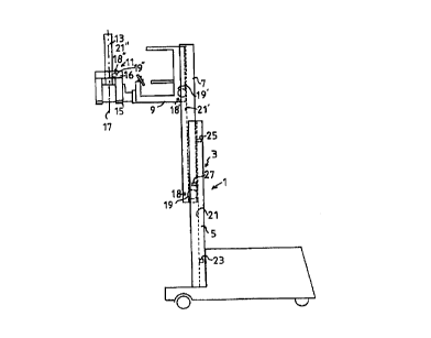
Fig. 1 shows a greatly simplified side view of an industrial lift truck
according to the invention,
Fig. 2 shows phase-shifted pulse signals as are emitted by angular position
sensors of the position measuring device, and
Fig. 3 shows a simplified partial representation of a telescoping lifting
frame to explain a preferred referencing process.
The lift truck 1 in Fig. 1 is a three-way, order-picking lift truck. The lift
truck 1 has a telescoping lifting frame 3 with a lower lifting frame section
5, which
is stationary relative to the chassis of the lift truck 1, and an upper
lifting frame
section 7, which can extend and retract in a vertical direction relative to
the lower
lifting frame section 5, upon which is arranged an operator's cab 9 so as to
be
adjustable in height. Located on the front of the operator's cab 9 is a
rotary/linear
positioner 11 which is arranged so as to be laterally movable relative to the
operator's cab 9, e.g. perpendicular to the plane of the drawing in Fig. l,
and which
has an auxiliary lifting frame (auxiliary mast) 13, upon which a load lifting
device
(fork) 15 is attached by its mount 16 so as to be adjustable in height
relative to the
operator's cab 9. The auxiliary mast 13 can be pivoted together with the load
lifting
device 15 by approximately 180° about an axis 17.
As the sensor of a position measuring device, there is arranged on the upper
3o lifting frame section 7 a roller bearing 18 in the form of an incremental
angular
NY02:238341.1
CA 02296340 2000-O1-14
_7_
position sensor whose rotatable outer ring 19 serves as a roller body with a
roller
axis perpendicular to the direction of lift of the upper lifting frame 7,
where the
circumference of the roller body 19 contacts a surface 21 of the lower lifting
frame
section 5 which forms a path running in the direction of lift of the upper
lifting
frame section 7, upon which the roller body 19 rolls when the upper lifting
frame
section 7 moves in telescoping fashion relative to the lower lifting frame
section 5.
The rollei bearing 18 is attached to the lifting frame section 7 in such a way
that
the roller body 19 is elastically preloaded toward its path 21, and thus is
always in
contact with the path.
to In Fig. 1, the upper lifting frame section 7 is shown partially extended,
while the cab 9 is shown in its uppermost position relative to the upper
lifting
frame section 7. The load lifting device 15 is in its lowest position relative
to the
auxiliary mast 13 and is pivoted to the side toward the viewer as shown in
Fig. 1.
The hydraulic drive devices for elements 7, 9, 1 l and 15 are not shown.
15 When the roller body 19 rotates, the angular position sensor 18 emits two
pulse trains in quadrature in the form of electric signals as indicated in
Fig. 2. Each
pulse interval corresponds to a specific change in the angular position of the
roller
body 19. The phase-shifted electrical signals are supplied to an analysis
circuit (not
shown) that has an up/down counter circuit to count the measurement signal
pulses
20 and determines the direction of rotation by comparing the two measurement
signals. When the upper frame section 7 is raised, the counter circuit
increments
the pulse count of the appropriate measurement signal, whereas the counter
circuit
decrements the pulse count when the upper frame section 7 is lowered and the
associated reversal takes place in the direction of rotation of the roller
body 19.
25 The analysis circuit determines the position of the upper lifting frame
section 7
relative to the lower lifting frame section 5 from the pertinent count value.
The
analysis circuit can also determine the appropriate lift speed from the pulses
counted per unit time, in which process the lift speed values can be used as
actual
values for lift speed regulation, for example as a function of the current
position of
3o the upper lifting frame section 7 relative to the lower lifting frame
section 5, on the
NY02:238341. I
CA 02296340 2000-O1-14
_g_
basic principle that the lift speed is reduced in a controlled fashion when
the upper
lifting frame 7 approaches its maximum permissible lift height position or
another
predefined position.
In the exemplary embodiment in Fig. 1, reference sensors are additionally
provided for the position measuring device. In this example, these are
proximity
sensors 23 and 25, which are arranged on the lower lifting frame section 5 and
transmit an appropriate reference signal to the analysis circuit when they are
opposite a reference sensor element (marking) 27 attached to the upper lifting
frame section 7 at a predetermined location. Using the reference signal, the
to analysis circuit can check the position value derived from the angular
position
sensor 18 and correct it if necessary. Moreover, the reference sensors can be
used
to calibrate the measurement range of the position measuring device, where the
upper lifting frame section 7 is extended starting from its lowest base
position so
that the reference sensor element 27 is passed by the proximity sensors 23 and
25
15 in sequence. The analysis circuit determines the number of pulses per
channel
emitted by the angular position sensor 18 between the appearance of the first
reference signal from proximity sensor 23 and the appearance of the second
reference signal from proximity sensor 25, in order to normalize the
predetermined
distance between proximity sensors 23 and 25 so that a very exact relationship
20 between position changes of the upper lifting frame section 7 and changes
in
angular position of the roller body 19 can be established. The sensors 23 and
25
can take the form of inductive proximity sensors, light beam switches or the
like,
and if necessary can take on additional functions, for instance as part of an
endpoint detection circuit.
25 For referencing, one could also manage within the scope of the invention
with just one reference sensor, for example reference sensor 23, which is
arranged
for instance at a predetermined distance above the lowest possible position of
the
reference element 27 which the reference element 27 assumes when the upper
lifting frame section 7 is fully retracted in its lowest base position.
Another
NY02:238341. l
CA 02296340 2000-O1-14
-9-
possibility is to use just one reference sensor where the relevant reference
sensor
and the reference sensor element interact over a predetermined lift distance.
For the propose of explaining another referencing method, Fig. 3 shows a
lower lifting frame section 5a, and an upper lifting frame section 7a that can
move
in telescoping fashion relative thereto, of an adjustable-length lifting frame
of an
industrial lift truck in accordance with the invention.
In Fig. 3, the upper lifting frame section 7a is shown in a position in which
it is raised a predetermined reference distance r as compared to its lowest
possible
rest position. The sensor 23a at the height of the reference distance r
changes its
to ' output signal when the lifting frame section 7a extends upward past the
reference
distance r or reenters the reference distance region while moving down. Fig. 3
shows the upper lifting frame section 7a in a snapshot in which it is evoking
a
signal state change in the sensor 23a. From the signal state of sensor 23, an
unambiguous determination can be made as to whether the lifting frame section
7a
is outside the reference distance region r and must be lowered to bring its
lower
end into the reference distance region r for referencing.
For example, the following referencing process can take place:
1. Starting from the fully lowered base position of lifting frame section 7a,
the
lifting frame section 7a is raised until a signal state change is detected at
2o sensor 23a. The signal state change indicates that sensor 23a is
functioning.
2. Starting from the position shown in Fig. 3, the lifting frame section 7a is
lowered the entire reference distance r until it has reached its lowest base
position. During the process of lowering lifting frame section 7a, the
analysis circuit checks the two phase-shifted electrical signals from angular
position sensor 18a for the correct phase relationship for the case of
lowering. In addition, the angular position sensor signal is evaluated in
order to measure the reference distance r.
NY02:238341.1
CA 02296340 2000-O1-14
- 10-
3. The lifting frame section 7a is again raised from the lowest base position
until the reference sensor 23a changes its initial signal state.
The analysis circuit checks the phase-shifted electrical signals from the
angular position sensor 18a for the correct phase sequence for the case of
raising. In addition, the reference distance r is measured.
If the lifting frame section 7a is initially located outside the reference
distance region r, the referencing can be performed in an appropriate
fashion, omitting Step 1 above.
The following problems can be detected by the referencing process
described above:
- failure in the reference sensor 23a
- failure in or faulty signal of the angular position sensor 18a,
- any elongation or stretching of the lift chain customarily used to extend
the
lifting frame section 7a,
- faults in the analysis circuit or counter circuit.
Fig. 3 also shows the option that the angular position sensor 18a is arranged
2o on the stationary lifting frame section in such a way that it can rotate
and is set in
rotation when the movable lifting frame section 7a is moved upward or
downward.
In the exemplary embodiment shown in Fig. 1, an angular position sensor
18' corresponding to the angular position sensor 18 is arranged on the
operator's
cab 9; the associated roller body 19' rolls on a path 21' running in the
lengthwise
direction of the upper lifting frame section 7 when the operator's cab 9 is
raised or
lowered relative to the upper lifting frame section 7. For determining the
position
of the operator's cab 9 relative to the upper lifting frame section 7 or to
the lower
lifting frame section 5, the analysis circuit evaluates the appropriate pulse
signals
NY02:238341.1
CA 02296340 2000-O1-14
-11-
of the angular position sensor 18' arranged on the operator's cab 9. Reference
sensors of the type described above can also be used for determining the
position
of the operator's cab 9.
An additional angular position sensor 18" corresponding to the angular
position sensor 18 is arranged on an element 16 that is rigidly connected to
the
load lifting device 15; the associated roller body 19" rolls on a vertical
path of the
auxiliary mast 13 when the load lifting device 15 is raised or lowered
relative to
the auxiliary mast 13. The analysis circuit also evaluates the pulse signals
of the
latter angular position sensor 18" and can determine, from the relevant
angular
to ' position sensor information, the lift height of the load lifting device
15 relative to
the operator's cab 9 and relative to the lifting frame sections 7 and 5.
Of course, an angular position sensor corresponding to the angular position
sensor 18 can also be provided on the operator's cab 9 for measuring the
lateral
extension of the load lifting device 15.
The invention makes possible precise position monitoring, which is
accomplished with simple means, of the load lifting device and/or of the
elements
that can move with the load lifting device (elements 7, 9, 1 l and 16 in the
exemplary embodiment) relative to one another and relative to a fixed
reference
point on the industrial lift truck. The values for position and rate of change
of
position provided by the position measuring device can be used, for example,
as
instantaneous feedback comparison values for a drive control unit that
controls the
movement sequences of these elements.
rrYOZ:us3a~. i