Note: Descriptions are shown in the official language in which they were submitted.
CA 02296417 2000-01-14
WO 99/08855 PCTIUS98/16400
VACUUM EXTRUSION SYSTEM AND METHOD
BACKGROUND OF THE INVENTION
Such prior application discloses a horizontal barometric leg of the type shown
in
Pagan U.S. Patent No. 4,783,291. In the Pagan patent, a vacuum chamber
includes an
extrusion die at one end forming an extrudate. After passing through sizing,
calibration
and draw off equipment, for example, the extrudate exits the vacuum chamber
through a
water baffle. The extrudate passes over a dam and dips into a pond to exit the
chamber
through the pond. The pond has two sections or levels, one with a higher level
within the
chamber during vacuum and one with a lower level outside the chamber. A
circulating
system keeps the pond level within the chamber from overtopping the dam during
vacuum
extrusion. The pond provides full immersion cooling during vacuum extrusion as
well as
providing a continuous water baffle seal for the extrudate exiting the
chamber. The
extrudate may be cut and processed in atmosphere after it leaves the lower
level or section
of the pond outside the chamber.
In such prior Lightle, et al. application there is disclosed a horizontal
barometric
leg vacuum extrusion line with a support truss extending from the dam to a
fixed
bulkhead, the die being mounted on the end of the extruder projecting through
the fixed
bulkhead. Calibration and sizing or draw-off equipment is mounted on the
truss.
The chamber surrounding the truss includes a fixed section and a telescoping
section which can move away from the bulkhead telescoping over the fixed
section to
provide access to the die and the downstream equipment.
If some of the downstream equipment is within the fixed section, the fixed
section
is entered as one would a cave or tunnel. The system with the single movable
section
telescoping over the fixed section is quite adequate for medium to low through-
puts, but is
not necessarily adequate for large through-puts and/or extrudate cross-
sections with
foaming extrudates. Through-puts are normally expressed as pounds or kilograms
per
hour. For example, smaller through-puts typically may be two hundred pounds
(90.7200
kilograms) per hour or less, while larger through-puts may typically be two
thousand
pounds (907.2000 kilograms) per hour or more.
When a mishap or mayhap occurs, especially during system start-up, the
operators
need to open the chamber quickly and obtain access to the errant downstream
equipment
quickly. The operators not only need access quickly, they need access with an
adequate
1
CA 02296417 2006-09-20
spatial working environment. Without such, the vacuum chamber may literally
fill up or
start to fill up with extrudate, especially foam extrudate, requiring the
whole system to be
shut down.
With higher through-puts, problems need to be addressed more quickly, and the
chamber of the system requires larger volume around the downstream equipment,
not only
to accommodate the equipment, but also operators around the equipment with
adequate
spatial working environment to obtain access to the equipment and any
misdirected
extrudate.
SUMMARY OF THE INVENTION
The vacuum chamber is disclosed which may utilize a fixed large diameter
entrance
bulkhead plate. A first section with a large diameter can be movable and seal
against a
second larger section, and telescope over a smaller diameter fixed section
which includes
the dam and the higher level portion of the pond of the water baffle seal. The
second larger
section may move within the gap created by movement of the first, and seals
against the
first and entrance bulkhead plate. A truss supporting the downstream equipment
may extend
from the dam to the fixed bulkhead through the movable large diameter
sections. In this
manner all of the downstream equipment may be mounted within the two movable
large
diameter sections providing adequate volume for large through-puts as well as
a good
spatial working environment.
Both large diameter sections may quickly be opened with the first telescoping
over
the smaller fixed section, and the second section may be moved with the first
section or
within the gap provided by the first section. In this manner any portion of
the downstream
equipment may quickly be completely exposed.
The first section may be locked to the fixed section, and fluid seals may be
employed between the bulkhead and second section, the first and second
section, and the
first section and fixed section, quickly to reestablish the integrity of the
vacuum chamber.
Both larger diameter sections may be power operated to move concurrently or
independently.
2
CA 02296417 2006-09-20
In order to achieve quick access and to open and lock the vacuum chamber,
there
may be provided a simplified quick acting preferred lock system between the
fixed and a
moving section of the vacuum chamber. The lock system may utilize pneumatic
piston-
cylinder assemblies driving lock blocks behind fixed stop blocks, forcing the
sections
together in a direction opposite the forces generated by the fluid seals. A
preferred lock
system may be utilized whether the fixed and moving sections are substantially
the same
size or substantially different in size.
According to one aspect of the invention, there is provided a vacuum extrusion
line
comprising a vacuum chamber having a die at one end inside a chamber and a
water baffle
immersion cooler at the other end for extracting the extrudate to atmosphere,
and
downstream extrudate shaping and sizing equipment all inside the chamber, and
a chamber
sealing means operative to open the chamber fully laterally selectively to
expose the die and
any of the downstream equipment.
According to another aspect of the invention, there is provided a vacuum
extrusion
line comprising a vacuum chamber having a die at one end inside the chamber
and a water
baffle immersion cooler at the other end for extracting an extrudate to
atmosphere, and
downstream extrudate shaping and sizing equipment all inside the chamber, the
chamber
comprising a fixed section, and at least two movable sections which can be
relatively
movable with respect to the fixed section and each other selectively fully to
expose any of
the die and downstream equipment to permit quick access thereto.
According to another aspect of the invention, there is provided a vacuum
extrusion
line comprising a vacuum chamber having a die at one end inside the chamber
and a water
baffle immersion cooler at the other end for extracting an extrudate to
atmosphere, and
downstream equipment for extrudate shaping and sizing all inside the chamber,
the chamber
comprising a fixed section and at least two movable sections, one movable
section which
telescopes over the fixed section to form a gap between movable sections, with
the other
movable section then being movable within the limits of the gap selectively
fully to expose
the die and downstream equipment.
According to another aspect of the invention, there is provided a vacuum
extrusion
system including a vacuum chamber having a fixed and movable section, the
movable
3
CA 02296417 2006-09-20
section being mounted for telescopic movement over the fixed section to open
the chamber,
stop blocks on the fixed section, and respective lock blocks on the movable
section
operative to be driven against the stop blocks by respective cylinder
actuators to lock the
sections closed.
To the accomplishment of the foregoing and related ends, the invention then
comprises the features hereinafter fully described and particularly pointed
out in the claims,
the following description and the annexed drawings setting forth in detail
certain illustrative
embodiments of the invention, these being indicative, however, of but a few of
the various
ways in which the principles of the invention may be employed.
BRIEF DESCRIPTION OF THE DRAWINGS
Figure 1 is a somewhat schematic side elevation of a vacuum chamber section of
a
foam extrusion line in accordance with the invention with the chamber fully
closed;
Figure 2 is a similar schematic showing one enlarged section opened and
telescoped
to expose some of the take-off equipment;
Figure 3 is a similar schematic showing a second enlarged section open and
shifted
with the one to expose some of the take-off, shaping or calibrating equipment
and the die;
Figure 4 is a section taken substantially on the line 4-4 of Figure 1 showing
the
eccentric fixed and the larger telescoping first section;
Figure 5 is an enlarged fragmentary axial elevation of one form of lock;
Figure 6 is a fragmentary view of the lock of Figure 5 actuator;
Figure 7 is a fragmentary axial section from the fixed section to the fixed
bulkhead
showing the lock of Figure 5 and the fluid actuated seals;
Figure 8 is a view like Figure 4 but illustrating the preferred lock system;
and
Figure 9 is a fragmentary broken section of the lock system of Figure 8 taken
substantially on the line 9-9 of Figure 8.
4
CA 02296417 2006-09-20
DETAILED DESCRIPTION OF THE ILLUSTRATED PREFERRED EMBODIMENTS
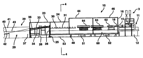
Referring now to the drawings and more particularly to Figures 1 through 3 the
vacuum chamber section of a foam extrusion line is shown generally at 10. At
the right hand
or upstream end of the line there is provided one or more extruders shown
generally at 11.
The extruders are mounted on a stand 12 and include one or more hoppers 13 by
which the
raw materials are fed to the extruder barrel 15 to be formed under heat and
pressure into a
foamable plastic melt. An extension of the extruder barrel may project through
a large
diameter fixed bulkhead plate indicated at 16 with the die 18 being mounted on
the end of
such extension within the vacuum chamber. The extruder barrel may extend
through a gland
as shown in applicants' U.S. Patent No. 5,783,122 entitled "Vacuum Extrusion
Apparatus
and Method". The die 18 is thus within the chamber and interior of the
bulkhead 16. The
bulkhead forms the upstream end of the vacuum chamber 10. The opposite or
downstream
end is in the form of a water baffle immersion cooler shown generally at 20.
The chamber at
such water baffle end may include interconnected fixed cylindrical sections 23
and 24
which are mounted on fixed stanchions 25 on the floor 26. A fixed exit
bulkhead in the form
of a dam is provided at 28 near the joint of the two fixed sections 23 and 24,
which forms a
pond or reservoir 29, one end of which is in essentially all of the section
23. In the section
24 there may be provided a roller conveyer 30 having rollers 31 providing
support beneath
the extrudate. As the extrudate passes over the top of the dam 28, guide
rollers may be
provided both above and below the extrudate as indicated at 33 and 34,
respectively. These
conveyor rollers cause the extrudate to deflect or dip downwardly through a
slight curve
after having passed over the dam to enter the pond 29 of water. The level of
the pond within
the chamber when under vacuum is shown at 36.
The extrudate passes into a hood 37 and exits the hood beneath the section of
the
pond indicated at 40 exposed to atmosphere in open pond containment 41. The
extrudate is
still guided by the conveyor system indicated at 42 on the top of the
extrudate. At this point
the extrudate will float upwardly against the conveyor system. The extrudate
continues
through the pond section 40 and exits to atmosphere for cutting and
processing. The details
of the water baffle and conveyor system for removing the extrudate from the
vacuum
chamber to the processing point may be seen in the co-pending application of
Lightle et al.
noted above. Under vacuum, the level of the pond indicated at 36 is somewhat
above the
4a
CA 02296417 2006-09-20
level 43 of the pond 29 exposed to atmosphere. The pond is kept from
overtopping the dam
28 by circulating the water back to the atmospheric end of the pond. Again
this is shown in
the prior Lightle et al. application.
Positioned upstream of the fixed section 24 of the vacuum chamber is a
substantially larger movable section shown generally at 44. A second movable
section of
the same larger diameter is provided at 46, and it will be noted that the
fixed bulkhead 16
4b
CA 02296417 2000-01-14
WO 99/08855 PCT/US98/16400
at the upper end of the upstream end of the chamber is of comparable diameter.
Both
movable sections are mounted on rollers indicated at 48, in turn mounted on
tracks 49
which run parallel to the extrusion line. At least one of the tracks and
mating rollers may
be a guide system to maintain alignment when the sections 44 or 46 are moved.
The
rollers and rails are seen more clearly in Figure 4.
Both large diameter movable sections 44 and 46 are provided with drive motors
seen at 51 and 52 which may engage chains mounted on the floor indicated at
53. The
drives 51 and 52 may be energized much as a garage door opener to move the
large
diameter sections 44 and 46 either concurrently or individually.
Extending from the dam 28 to the large diameter bulkhead 16 is a truss or beam
60. The truss may include rails serving as supports for the relatively complex
equipment
which is positioned downstream of the die 18 for calibration and sizing
purposes. For
example, the extrudate after leaving the die 18 may pass through a calibration
unit 62 and
a sizing or roller take-off 63, and finally a roller take-off 64. Such units
are fairly
complex and require, particularly at start up, adjustment and fine tuning.
With the present
invention access to the die, any shaping mechanism downstream of the die, and
the
complex calibrating and take-off equipment can be had very quickly by movement
of one
or both of the large diameter movable sections. The large diameter of the
movable
sections provides the necessary clearance for an operator working in the
spatial
environment of the downstream equipment or die and also provides a large
volume should
a foaming extrudate errantly deviate from its intended path.
In comparing Figures 1, 2 and 3 it will be seen that the first movable
enlarged
section 44 can be opened and closed by telescoping over the fixed section 24.
Both
sections may be cylindrical and eccentric as seen in Figure 4. When the first
section 44 is
opened the relative position of the sections as seen in Figure 2 provides a
significant gap
indicated at 68 between the sections 44 and 46. This exposes the take-off 64
and part of
the take-off 63. If access to the take-off 63 or the calibrating equipment 62
or die 18 is
required, the enlarged section 46 is simply moved into the gap 68 to achieve
the position
seen in Figure 3. With the motors 51 and 52 the two enlarged sections may be
moved
concurrently to the position seen in Figure 3 exposing the die and equipment
at the
upstream end of the vacuum chamber as indicated by the gap 69.
Referring now to Figures 4 through 7 it will be seen that the first section 44
has an
end plate 72 forming an annular interior opening 73 through which the flanged
ring 74 of
5
CA 02296417 2000-01-14
WO 99/08855 PCT/US98/16400
the fixed section 24 extends. The plate in one form may be provided with an
annular
shoulder 75 supporting track ring 76 for roller chain 77 supporting locking
plates 78. The
roller chain may be moved around the track by a piston-cylinder actuator 79.
The blind
end of the cylinder is pivoted at 80 to the plate 72 while the rod end is
pivoted at 82 to
bracket 83 secured to the roller chain as seen in Figure 6. As seen in
comparing the right
and left hand sides of Figure 5, the reciprocation of the actuator will cause
the locking
plates to move from a clear position shown between a series of spaced
projections 84 and
85 to a locking position behind such projections, and vice versa. The relative
position of
the locking plates and projections is seen in Figures 5 and 7. The projections
are on the
end of the fixed section. The locking plates are mounted on the roller chain
on the end of
the movable section. When the piston-cylinder assembly is actuated to obtain
the
clearance position, one or both of the large diameter movable sections may be
moved
selectively as shown in Figures 2 and 3.
The diameter of the bulkhead and movable sections may be substantial being on
the order of fourteen feet (4.62 meters) or more, while the fixed section may
be on the
order of ten feet (3.05 meters). The enlargement ratio is thus on the order of
about ten to
about fourteen or more.
As seen in Figure 7, in order to seal the larger diameter sections, an annular
fluid
expansible seal is provided at 88 between the fixed section 24 and the movable
section 44.
A similar annular fluid sea189 is provided between the two large movable
sections 44
and 46, while an annular fluid seal 90 is provided between the section 46 and
the fixed
bulkhead 16. With the locking plate 78 in the locking position behind the
projections 84
and 85, the expansion of the seals 88, 89 and 90 will take up any clearance
indicated at 92
seen in Figure 7 providing a fixed abutment between the movable section and
the fixed
section 24. The expansion of the seals will then provide a sealed vacuum
chamber. It is
noted that when the vacuum chamber is open, the pond leve136 within the
chamber is at
the same level as the leve143 outside the chamber. With the chamber closed,
the vacuum
can quickly be restored.
Referring now to Figures 8 and 9, there is illustrated a preferred locking
system
for the present invention whether the fixed and telescoping sections are of
substantially
different or similar sizes. The locking system utilizes pneumatic piston-
cylinder assembly
actuators shown at 92, 93, 94, 95, 96 and 97 in Figure 8. The actuators are
spaced equally
60 apart around the center of the fixed section symmetrically on each side of
a vertical
6
CA 02296417 2000-01-14
WO 99/08855 PCT/US98/16400
plane through the center.
The blind end of each actuator is pivoted between parallel plate brackets 99
at 100.
The brackets extend from the plate 72. Each actuator rod has fixed thereto a
lock block
102 which as a transverse follower rod 103, the projecting ends of which ride
in cam slots
105 in each bracket plate. The slots are inclined with respect to the axes of
the sections
and move the lock blocks radially inwardly as the rods of the actuators extend
and radially
outwardly as the actuators retract. When retracted in the full line position
shown, the
blocks are radially clear of respective stop blocks 107 secured to the
exterior of fixed
section 24. When extended to the phantom line position 109, the lock blocks
engage
behind and abut against the stop blocks, preventing the opening or telescoping
of the two
sections 44 and 24.
The pressure within the cylinders 92 drives the two movable sections to the
right
as seen in Figure 9, while pressure within the fluid seals 88, 89 and 90 is
counteractive.
The lock system of Figures 8 and 9 is prefened for its simplicity and short
cycle of action.
The system can be used whether the telescoping sections are of similar or
dissimilar size.
It can now be seen that there is provided a vacuum extrusion system
particularly
useful for the production of low density foams with the vacuum chamber
utilizing a fixed
large diameter entrance bulkhead plate with first and second large diameter
movable
sections. The first section with the larger diameter is movable and seals
against a second
section, and telescopes over a smaller diameter fixed section which includes a
dam
forming part of a full immersion water baffle seal permitting the extrudate to
exit the
chamber. The second section may move within the gap created by movement of the
first
section and seals against the first section and an entrance bulkhead plate. A
truss
supporting the complex downstream equipment extends from the dam to the fixed
bulkhead through the movable large diameter sections. In this manner all of
the
downstream equipment may quickly and conveniently be exposed with proper
spatial
environment for the operator and any errant extrudate. The vacuum chamber can
quickly
be restored and sealed after any problems are corrected. The volumetric and
access
capability is important on start up for large through-put extrusions.
To the accomplishment of the foregoing and related ends, the invention then
comprises the features particularly pointed out in the claims, these being
indicative,
however, of but a few of the various ways in which the principles of the
invention may be
employed.
7