Language selection

Search

Patent 2296502 Summary

Third-party information liability

Some of the information on this Web page has been provided by external sources. The Government of Canada is not responsible for the accuracy, reliability or currency of the information supplied by external sources. Users wishing to rely upon this information should consult directly with the source of the information. Content provided by external sources is not subject to official languages, privacy and accessibility requirements.

Claims and Abstract availability

Any discrepancies in the text and image of the Claims and Abstract are due to differing posting times. Text of the Claims and Abstract are posted:

  • At the time the application is open to public inspection;
  • At the time of issue of the patent (grant).
(12) Patent Application: (11) CA 2296502
(54) English Title: ARTICLE DISPLACEMENT INDICATION
(54) French Title: INDICATION SUR LE DEPLACEMENT D'ARTICLES
Status: Dead
Bibliographic Data
(51) International Patent Classification (IPC):
  • G08B 13/08 (2006.01)
(72) Inventors :
  • BAGLIN, NEIL ERNEST (United Kingdom)
(73) Owners :
  • BAGLIN, NEIL ERNEST (United Kingdom)
(71) Applicants :
  • BAGLIN, NEIL ERNEST (United Kingdom)
(74) Agent: MACRAE & CO.
(74) Associate agent:
(45) Issued:
(86) PCT Filing Date: 1998-07-16
(87) Open to Public Inspection: 1999-01-28
Examination requested: 2002-09-05
Availability of licence: N/A
(25) Language of filing: English

Patent Cooperation Treaty (PCT): Yes
(86) PCT Filing Number: PCT/GB1998/002119
(87) International Publication Number: WO1999/004376
(85) National Entry: 2000-01-07

(30) Application Priority Data:
Application No. Country/Territory Date
9714855.5 United Kingdom 1997-07-16

Abstracts

English Abstract


A device for indicating/limiting the overall displacement of a movable member
from a preset position, wherein the device (1) is selectively positionable to
accomodate variation in allowable displacement of the movable member (32, 38,
39, 42, 49, 50, 52) prior to preventing displacement of the movable member or
for providing an indication of any such displacement of the member.


French Abstract

La présente invention concerne un dispositif permettant d'indiquer ou de limiter le déplacement global d'un élément mobile depuis une position prédéfinie, le dispositif (1) étant sélectivement plaçable de façon à tenir compte des variations dans le déplacement autorisé de l'élément mobile (32, 38, 39, 42, 50, 52) avant d'empêcher son déplacement, ou encore pour fournir une indication sur n'importe quel déplacement de cet élément.

Claims

Note: Claims are shown in the official language in which they were submitted.


-12-

CLAIMS
1. A device for indicating and/or preventing
displacement or for indicating and/or limiting the
overall displacement of a movable member (32, 38, 39, 42,
49, 50, 52) from a preset position, wherein the device
(1) is adapted to be selectively positionally mountable
to the movable member.
2. A device as claimed in claim 1, and characterised
in that the device (1) is adapted to enable predetermined
variations in allowable displacement of the movable
member (32,38,39,42,49,50 52) prior to preventing further
displacement of the member and/or for providing an
indication of any such displacement of the movable
member.
3. A device adapted for releasable attachment to a
movable member (32,38,39,42,49,50 52), at such position
as to be able to contact a non-movable region relative to
which the movable member is displaceable following a
predetermined amount of displacemen of the movable
member, the device (1) including means (24) for producing
an indication that such allowed amount of displacement
has been attained.
4 A device as claimed in claim 1, 2 or 3, and
characterised in that wherein the device (1) is responsive
is a linear displacement of the movable member
(32,38,39,42,49,50 52).
5. A device as claimed in claim 1, 2 or 3, and
characterised in that the device (1) is arranged to
respond to an angular displacement of the movable member
(32,38,39,42,49,50 52).


-13-
6, A device as claimed in claim 1, 2 or 3, and
characterised in that the device (1) is responsive both
linear displacements and angular displacements of the
movable member (32,38,39,42,49,50 52).
7, A device as claimed in any one of claims 1 to 5,
and characterised in that the device (1) is arranged on
operation to provide an indication of unauthorised
displacement of the movable member (32,38,39,42,49,50
52)in the form of an an audible and/or visual warning
signal.
8, A device as claimed in any one of the preceeding
claims, and characterised in that the device includes a
main body (2,3,4) and a device mounting part (5,17,18)
adapted for positional adjustment relative to the main
body (2,3,4) upon actuation of a device operation setting
element (8), and in that the device mounting part
(5,17,18) is adapted for attachment to a smooth surface
by means of a suction induced sealing effect produced
between the device mounting part and said surface.

9, A device as claimed in claim 8, and characterised
in that the device mounting part includes a plate (13)
encapsulated in an elastomeric covering (20) providing an
exposed outer surface, the covering including an
outwardly extending peripheral region (17) which is
arranged in conjunction with the remainder of the exposed
outer surface (18) to define a suction/vaccuum type
sealing surface.


-14-
10. A device as claimed in claim 8 or 9, and
characterised in that the device mounting part (5,17,18)
is operationally coupled to the main body part by way of
a rotatable cranked lever arrangement(8,9), the
arrangement being such that the lever arrangement can be
actuated in such manner as to pull the device mounting
part (1,17,18) towards the main body and thereby to
produce, when the device mounting part has been placed
against a smooth surcface a suction induced sealing
effect between the device mounting part and said surface.
11. A device as claimed in any one of the preceeeding
claims, and characterised in that the device (1) includes
an electronic circuit including means (21) responsive to
linear displacements of the device.
12. A device as claimed in any one of the preceeeding
claims, and characterised in that the device includes an
electronic circuit including means (26) responsive to
angular displacements of the device.
13. A device as claimed in any one of the preceeeding
claims, and characterised in that the device includes an
electronic circuit including means (21,26) responsive to
both linear and angular displacements of the device.
14. A device as claimed in claim 11 or 13, and
characterised in that the device responsive to said
linear displacements is a trembler switch (21).
15, A device as claimed in claim 12, 13 or 14, and
characterised in that the device responsive to said
angular displacements is a tilt responsive switch (26).


-15-
16. A device as claimed in any one of claims
11 to 15, and characterised in that the circuit includes
a timer unit (27) for enabling selectice control over the
duration of operation of electronic circuit in producing
said indication.
17. A device as claimed in claim 16, and
characterised in that the circuit includes operation
repeater means (28), whereby the device can be caused to
repeat its indication from time to time until the device
has been monitored.
18. A method of indicating and/or preventing
displacement or for indicating and/or limiting the
overall displacement of a movable member (32, 38, 39, 42,
49, 50, 52) from a preset position including the step of
positionally mounting to the member a device (1) adapted
to be selectively positionally mountable to the member,
the device including means (21,26) for producing an
indication that an allowed amount of displacement has
been effected.
Description

Note: Descriptions are shown in the official language in which they were submitted.


CA 02296502 2000-O1-07
WO 99/04376 PCT/GB98/02119
ARTICLE DISPLACEMENT INDICATION
This invention relates to a means for indicating
displacements of linearly and/or angularly displaceable
objects, and/or for maintaining a predetermined setting
of such objects relative to a reference location.
In particular, but not exclusively, the present invention
is concerned with indicating the pasition of slidable
members and/or tiltable members relative to a fixed
position such as a framework in which the members are
mounted for slidable or tiltable movement.
Many premises are provided with sliding type doors and
windows. For example, large area sliding doors that are
often referred to as patio doors. In the case of
windows there are the well known sash types which are
opened and closed by vertically sliding one part of the
window unit relative to another part of the window unit.
Window constructions are also known which are inclinable
relative to the window frame whilst others are both
bodily openable about a vertical axis and also titable
about a horizontal axis.
A further form of window construction involving
relatively slidable parts are those which include
sections which are relatively displaceable in a
horizontal direction.
Other forms of window construction are those which are
tilted about a horizontal axis during the opening and
closing operations.
As is well known, an important factor in relation to the
security afforded by doors or windows is the ease by
which a door or window can be opened without legitimate


CA 02296502 2000-O1-07
WO 99/04376 PCT/GB98/02119
-2-
users of a property becoming aware that a window or door
of the property is being displaced from its closed or
from a previously set part open setting.
Security systems serving to detect when a window or door
is subjected to unauthorised opening are known.
These known systems are not generally totally applicable
in their application to doors and windows as presently
used in many premises and may be presently already
installed since they can be regarded as being restricted
in their application by being able only to provide
indication as to whether or not a door or window is open
or closed. Thus these known systems are not suitable for
accommodating the degree/extent of or changes in the
amount of opening of such doors and windows.
It is an object of the present invention to provide an
improved security device in relation to the security
afforded by doors and/or windows.
Broadly, according to a first aspect of the present
invention there is provided a device for
indicating/preventing displacement or for
indicating/limiting the overall displacement of a movable
member from a preset position, wherein the device is
adapted to be selectively positionally mountable to the
member.
Preferably, the device is adapted to enable predeteminded
variations in allowable displacement of the moveable
member prior to preventing displacement of the member or
for providing an indication of any such displacement of
the member.
T


CA 02296502 2000-O1-07
WO 99/04376 PCT/GB98/02119
-3-
In accordance with a further aspect of the invention
there is provided a device adapted for releasable
attachment to the displaceable member, at such position
as to be able to contact a non-movable region relative to
which the movable member is displaceable following a
predetermined amount of displacement, the device
including means for producing an indication that such
allowed amount of displacement has been effected.
In accordance with a further aspect of the invention
there is provided a method of indicating/preventing
displacement or for indicating/limiting the overall
displacement of a movable member from a preset position
including the step of positionally mounting to the member
a device adapted to be selectively positionally mountable
to the member, the device including means for producing
an indication that an allowed amount of displacement has
been effected.
In a preferred application of the device the displacement
to which the device is responsive is a ~iuear
displacemenmt.
In a further preferred application of the device the
displacement to which the device responds comprises an
angular displacement.
Conveniently, the same device is able to respond to both
modes of displacement.
In a preferred arrangement the indication constitutes an
audible and or visual warning signal.


CA 02296502 2000-O1-07
WO 99/04376 PCT/GB98/02119
-4-
For a better understanding of the invention and to show
how to carry the same into effect reference will now be
made to the accompanying drawings in which:-
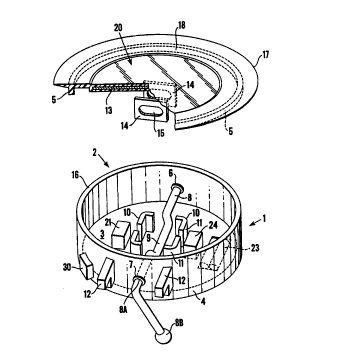
Figure 1 is a diagrammatic representation of a device
incorporating the concepts of the invention, the device
being shown both in part section and in exploded form;
Figure 2, schematically illustrates in block digram form
an electrical circuit for giving an indication of
displacement;
Figures 3,4, and 5, respectively illustrate alternative
modes of locating devices of the invention as applied to
various forms of door;
Figure 6, schematically illustrates the application of
the device of the invention to a composite window
95 assembly;
Figure 7 schematically illustrates the application of
the device of the invention to a tiltable window; and
Figure 8 schematically illustrates the application of
the device of the invention to a window commonly known as
20 a sash window.
Referring now to the drawings and more particularly to
Figure 1 in which a device 1 in accordance with the
invention is schematically represented.
The device 1 comprises a housing 2 including a first end
2ro wall structure 3, a cylindrical wall 2, and a second end
wall structure 5.
t


CA 02296502 2000-O1-07
WO 99/04376 PCT/GB98/02119
-5-
The cylindrical wall 2 is provided with diametrically
opposite circular openings 6 and 7 which are intended to
act as bearing surfaces for receiving and locating a
cranked operating element 8 that is cranked as at 9 in
such location that when the element 8 is engaged with the
bearing surfaces the cranked part is centrally located
relative to the diameter of the cylindrical wall 2. One
end of the operating element 8 is held in place by a
retaining nut (not shown) whilst the other end is
provided with an Allan key fitting whereby the element 8
can be rotated as required by a removable operating Allan
key 8A.
Two wall formations 10 are located in the central region
of the housing and are equidistantly spaced from the axis
of rotation of the cranked operating element 8. Each
wall formation 10 comprises two L-shaped elements 11
arranged effectively to form the corners of a rectangle.
Two lug-like elements 12 project outwardly from the wall.
These elements are intended to provide limit stops for
limiting the extent of rotation of the key 9A and thus
the rotation of the crank 9 within the housing 2.
In a modification the elements 12 are replaced by a
regular U-formation flange part, the side arms of which
part form the limit stops, with the U-formation serving
as a means for generally protecting the Allan key
fittings.
The end wall structure 5 comprises a circular metal plate
13 (shown in part section) having two upstanding lugs 14.
In the Figure 1 these are shown as being downwardly since
they need to be directed towards the interior of the
housing when the wall structure 5 is secured to the wall


CA 02296502 2000-O1-07
WO 99/04376 PCT/GB98/02119
-6-
2. Each such lug 14 is provided with an elongate aperture
15 .
The dimensions of the lugs 14 and the location thereof on
the plate 13 are such that when the end structure 5 is
mounted to the wall 4 the lugs 14 engage between the wall
formations 10 on the end structure 3. The crank part 9
of the operating element 8 are engagad with the elongate
apertures 15 during the mounting of the element for
rotation. It will be appreciated that during this
engagement the element will he suitably aligned to
facilitate and to enable the threading of the element
through the lug apertures 15.
The metal plate is encapsulated in an elastomeric
covering material which is shaped to provide the form of
the end structure 5 which latter is resiliently
engageable with the free annular end 16 of the wall 4 to
provide a firm
grip with the wall 4. In addition, the end structure 5
includes an outwardly extending peripheral annular part
17 which in conjunction with the remainder of the exposed
outer surface of the structure 5 defines an overall
surface I8 having a very smooth surface finish that
effectively defines a suction/vacuum type sealing
surface .
Thus, if the exposed surface 18 is placed against an
adequately smooth surface such as the surface of a glass
sheet (not shown) and the operating key 8B is engaged
with the element 8 Allan key fitting 8A and is operated
in such manner as to pull the lugs inwardly towards the
structure 3, and thus the central region of the outer
surface 18 inwards towards the remainder of the housinø;
z


CA 02296502 2000-O1-07
WO 99/04376 PCT/GB98/02119
_7_
a suction induced sealing effect is produced between the
said exposed surface 18 and the glass sheet. The
consequence of this suction effect is firmly to attach
the device 1 as so far discussed to the glass sheet.
g If the device 1 as so far discussed is mounted to the
glass of a slidable door it will be appreciated that on
sliding the door in its further opening direction the
device 1 as so far described will be caused to abut or
otherwise strike against the framing of the door. In
view of the suction attachment of the device 1 to the
slidable part of the door further movement movement is
stopped.
This 'stopping' effect is utilised according to the
invention to produce the audible and/or visual indication
that the door has been so displaced.
In accordance with a particular embodiment of the
invention apparatus responsive to the arresting of the
door movement is housed within the housing 2.
Figure 2 very schematically illustrates an electrical
2p circuit by means of which the aforementioned indication
can be produced. As will be seen from Figure 2 the
electrical circuit includes a so called trembler switch
21 which remains in a Quiescent switched-off condition so
long as the door to which the device is attached is not
subjected to motion arresting forces which would cause
the trembler switch 21 to actuate to a switched-on
condition.


CA 02296502 2000-O1-07
WO 99/04376 PCT/GB98/02119
_g_
The trembler switch 21 is electrically connected in the
positive voltage line 22 from a power supply 23 to an
audible sound emitting device 24. The negative line 25
of the power supply 23 is electrically connected to the
sound emitting device 24 to complete an electrical
circuit electrically controlled by the operational state
of the trembler switch 21.
In addition to the provision of the trembler switch 21 a
tilt responsive switch 26 is connected in parallel
therewith whereby the device of the invention is
responsive to any tilting of the surface to which the
device of the invention is attached in excess of an angle
defined by the tilt angle operation set into t~~ i.iiL
switch.
A timer unit 27 is provided for limiting the duration of
operation of the unit 24. If desired, an indication
repeater means 28 may be provided for causing the
indicator to repeat its indication output from time to
time until the device 1 has been monitored and reset.
A further switch 30 is provided to act as a switch for
arming the eletrical circuit as above discussed whereby
the electrical circuit is caused to become operational
when the operating key 8B is moved to the position in
which the suction effect is produced to secure the device
1 of the invention to an appropriate surface whose
position is to be monitored. This switch can be located
internally or externally, with the internal location
being preferred.
z


CA 02296502 2000-O1-07
WO 99/04376 PCT/GB98/02119
_g_
As will be appreciated the electrical circuit can be
provided in the form of a printed ciruit board and if
considered useful the various components can be
encapsulated.
It will be understood that the housing provided for the
electrical ciruitry can be of a construction differing
from that hereinbefore described since the main purpose
of the housing is to provide accommodation for the
electrical circuitry together with the provision of means
for enabling the housing to be secured to a glass
surface.
Figures 3 and 4 illustrates the mounting of devices I to
a
multi-door sliding door assembly 30 including doors 31
and 32 provided with associated frames 33 and 34 slidably
mounted in slide guides (not specifically shown) of a
main door frame 35 provided in a wall (not shown) and
providing the slide guides for the daors 31 and 32.
In Figure 3 the device I is shown to be positioned close
to the upper rail of the frame 34.
In Figure 4 the device 1 is located in the region of the
conventional level for a normally provided door operating
means (not shown).
By locating the device in the positions shown relative
movement of the doors 31 and 32 is prevented. Tr Will
be appreciated that if the devices 1 were to be located
at a locations to the right of those shown in the Figure
the doors would be capable of limited relative movement.


CA 02296502 2000-O1-07
WO 99/04376 PCT/GB98/02119
-10-
A further advantage arising from mounting the device
close to the upper rail of the slidable door frame 34 as
shown in Figure 3 is that any attempt to lift the sliding
door 32 upwardly from its guides in the frame 35 is
prevented, since any such attempt causes operation of the
trembler switch 21.
Figure 5 schematically illustrates a composite window
structure as commonly provided in residential properties.
As can be seen the structure includes a main framework
36 set into a wall for mounting a fixed sheet of glass
37, a tiltable window 38 and a pivoted swing window 39.
Figure 5 also schematically illustrates the application
of the device 1 to tilt type window 38 for the providing
indication of any displacement of the window 38 from a
preset position. In addition, the Figure illustrates the
use of the device 1 in conjunction with a locking chain
40 which connects with a conventional slide catch 41
provided on the frame 36. This arrangement provides a
means whereby the extent of the opening of the window 39
can be controlled.
Figure 6 schematically illustrates a door 42 and its
associated framework 43 mounted to a wall (not shown),
the door incorporating a number of separate pieces of
flat glass 44. In the Figure 6 device 1 is shown
mounted to one of the sheets of glass and connected by
way of a conventional door opening limitation chain 45
that couples with a positionally fixed slide catch 46.
In practice, the provision of the chains 40,45 and their
associated catches 41 and 46, has the result that if
anyone attempts to force the door, the resulting
t


CA 02296502 2000-O1-07
WO 99/04376 PCT/GB98/02119
-11-
interaction between the devices 1 and the associated
chains 40, 45 causes the trembler switch 21 to be set
into operation.
Referring now to Figure 7, this Figure schematically
illustrates a conventional sash type window 47 including
a main frame 48, and upper and lower slidable sashes 49
and 50. As shown a device 1 according to the invention
is attached to one of the panes of glass of the upper
sash at a location at the lower region of the upper sash.
With this arrangement the extent of allowable relative
displacement of the sashes 49 and 50 can be selectively
set.
Figure 8 illustates a tiltable window construction
including a main frame 51 and a tiltable window 52
pivotally mounted to the lower part of the frame 51.
By mounting a device I according to the invention any
departures from an allowable degree of tilt can be
monitored by reason of the tilt switch 26 provided in the
device 1.

Representative Drawing
A single figure which represents the drawing illustrating the invention.
Administrative Status

For a clearer understanding of the status of the application/patent presented on this page, the site Disclaimer , as well as the definitions for Patent , Administrative Status , Maintenance Fee  and Payment History  should be consulted.

Administrative Status

Title Date
Forecasted Issue Date Unavailable
(86) PCT Filing Date 1998-07-16
(87) PCT Publication Date 1999-01-28
(85) National Entry 2000-01-07
Examination Requested 2002-09-05
Dead Application 2006-07-17

Abandonment History

Abandonment Date Reason Reinstatement Date
2005-07-18 FAILURE TO PAY APPLICATION MAINTENANCE FEE

Payment History

Fee Type Anniversary Year Due Date Amount Paid Paid Date
Application Fee $150.00 2000-01-07
Maintenance Fee - Application - New Act 2 2000-07-17 $50.00 2000-04-27
Maintenance Fee - Application - New Act 3 2001-07-16 $50.00 2001-07-16
Maintenance Fee - Application - New Act 4 2002-07-16 $50.00 2002-07-16
Request for Examination $200.00 2002-09-05
Maintenance Fee - Application - New Act 5 2003-07-16 $75.00 2003-07-04
Maintenance Fee - Application - New Act 6 2004-07-16 $100.00 2004-06-08
Owners on Record

Note: Records showing the ownership history in alphabetical order.

Current Owners on Record
BAGLIN, NEIL ERNEST
Past Owners on Record
None
Past Owners that do not appear in the "Owners on Record" listing will appear in other documentation within the application.
Documents

To view selected files, please enter reCAPTCHA code :


To view images, click a link in the Document Description column. To download the documents, select one or more checkboxes in the first column and then click the "Download Selected in PDF format (Zip Archive)" or the "Download Selected as Single PDF" button.

List of published and non-published patent-specific documents on the CPD .

If you have any difficulty accessing content, you can call the Client Service Centre at 1-866-997-1936 or send them an e-mail at CIPO Client Service Centre.


Document
Description 
Date
(yyyy-mm-dd) 
Number of pages   Size of Image (KB) 
Representative Drawing 2000-03-15 1 14
Abstract 2000-01-07 1 53
Drawings 2000-01-07 11 359
Claims 2000-01-07 4 126
Drawings 2000-01-07 3 77
Cover Page 2000-03-15 1 42
Assignment 2000-01-07 3 85
PCT 2000-01-07 8 263
PCT 2000-01-08 1 34
Prosecution-Amendment 2002-09-05 1 33