Language selection

Search

Patent 2296564 Summary

Third-party information liability

Some of the information on this Web page has been provided by external sources. The Government of Canada is not responsible for the accuracy, reliability or currency of the information supplied by external sources. Users wishing to rely upon this information should consult directly with the source of the information. Content provided by external sources is not subject to official languages, privacy and accessibility requirements.

Claims and Abstract availability

Any discrepancies in the text and image of the Claims and Abstract are due to differing posting times. Text of the Claims and Abstract are posted:

  • At the time the application is open to public inspection;
  • At the time of issue of the patent (grant).
(12) Patent: (11) CA 2296564
(54) English Title: BRIDGING ARRANGEMENT
(54) French Title: SYSTEME DE CHEVAUCHEMENT
Status: Deemed expired
Bibliographic Data
(51) International Patent Classification (IPC):
  • E04F 15/00 (2006.01)
  • E04F 19/06 (2006.01)
(72) Inventors :
  • KEMPER, HANS A. (Germany)
  • SONDERMANN, FRANK (Germany)
(73) Owners :
  • HERM. FRIEDRICH KUNNE GMBH & CO. (Germany)
(71) Applicants :
  • HERM. FRIEDRICH KUNNE GMBH & CO. (Germany)
(74) Agent: SIM & MCBURNEY
(74) Associate agent:
(45) Issued: 2005-09-06
(86) PCT Filing Date: 1998-06-30
(87) Open to Public Inspection: 1999-01-14
Examination requested: 2001-11-16
Availability of licence: N/A
(25) Language of filing: English

Patent Cooperation Treaty (PCT): Yes
(86) PCT Filing Number: PCT/EP1998/003991
(87) International Publication Number: WO1999/001628
(85) National Entry: 2000-01-04

(30) Application Priority Data:
Application No. Country/Territory Date
297 11 606.1 Germany 1997-07-02

Abstracts

English Abstract


The invention describes a height-adjustable bridging device for joints
between floor coverings, consisting of an upper and a base element. On the
upper
element, at least one upper retaining bar is provided with a holding device
configured
to be bilateral to it. Also, arrayed on the base element are retaining bars
which project
upwards, which embrace the upper retaining bar bilaterally on its holding
device.
They have complementary holding devices. A support device is configured
between
the upper and the base element to prevent the upper element from tipping.


French Abstract

L'invention concerne un système de chevauchement (1) adaptable en hauteur, pour assurer une jointure entre des revêtements de sol. Ce système comprend un élément supérieur (2) et un élément de base (3), au moins une entretoise de retenue supérieure (4), pourvue d'un dispositif de retenue (5) formé de part et d'autre dessus, étant prévue sur l'élément supérieur (2). Des entretoises de retenue (6, 6') dirigées vers le haut sont disposées sur l'élément de base, entourent de part et d'autre l'entretoise de retenue supérieure (4) au niveau de son dispositif de retenue et comportent des dispositifs de retenue (5') complémentaires. Un dispositif d'appui (8) est réalisé entre l'élément supérieur (2) et l'élément de base (3) pour éviter tout mouvement de basculement de l'élément supérieur (2).

Claims

Note: Claims are shown in the official language in which they were submitted.


-5-

What is claimed is:

1. Height-adapted bridging device for joints between floor coverings,
consisting of an upper element and a base element, whereby on upper element at
least
one upper retaining bar is provided with a holding device configuration on it
bilaterally, and with retaining bars placed on the base element and projecting
upward,
which embrace upper retaining bar on its holding device and have complementary
holding devices, as well as a support device with a support bar which reduces
tipping
motion between the upper element and the base element, the support bar
operating in
conjunction with a force uptake piece placed at an interval from the retaining
bars on
the base element, and wherein the support bar has a tooth device, which acts
jointly
with an appropriate device on the force uptake piece.

2. Bridging device according to claim 1, wherein the force uptake piece is
a bar placed on the base element and pointing upwards.

3. Bridging device according to claim 1 or 2, wherein the force uptake
piece is a corrugation-shaped projection attached to the base element.

4. Bridging device according to any one of claims 1 to 3, wherein the
force uptake piece is arrayed on the side of the support bar which faces the
upper
retaining bar.

5. Bridging device according to one any of claims 1 to 4, wherein the
retaining bars are of differing heights.

6. Bridging device according to any one of claims 1 to 5, wherein one of
the retaining bars is lower than the other of the retaining bars, the lower
retaining bar
facing the support bar.


Description

Note: Descriptions are shown in the official language in which they were submitted.


CA 02296564 2004-11-12
"BRIDGING DEVICE"
The present invention relates to a height-adjustable bridging device for
joints.
Such height-adjustable bridging devices are used where a transition
must be created between a higher and a lower floor covering, such as between a
parquet floor and a rug, or between a door sill and a floor covering at a
lower level.
They are also used for same-height transitions at the doorsill or as an
expansion joint
for subdividing larger surfaces.
Especially at locations that are subject to heavy use, it is necessary to
replace a badly worn floor covering. In such a case, the bridging device
should be
loosened and re-used. The differing heights between such elements as a sill
and an
adjoining rug can be aligned by tapping on the upper element. However, here a
danger exists that the upper element will tip and move aside while being
tapped on.
From German Patent Document No. 296 00 057 a joint profile for floor
coverings is known in which a base strip has blades that point upwards and are
placed
at an interval from each other. On each of their sides that are oriented
inwards, they
are equipped with a sawtooth profile. The support device on the cover strip
consists
of two ribs placed at an interval from each other, each of which adjoins the
outer side
of the blade in gliding fashion. This embodiment shape has a disadvantage in
that it
cannot sufficiently carry out a supporting function, since it is configured to
yield too
readily. This flexibility is required to permit the blades of the base profile
to move
laterally outwards when the upper retaining bar is admitted, if the sawtooth
holders are
to move past each other until they reach their seating position. To make this
outward
motion possible, the ribs must be pliable. This, however, has the result that
insufficient supporting function is guaranteed.
Therefore, it is an object of the present invention of creating a height-
adjustable bridging device in which tipping and lateral motion are largely
avoided.
Accordingly, in one aspect of the present invention there is provided
height-adapted bridging device for joints between floor coverings, consisting
of an
upper element and a base element, whereby on upper element at least one upper
retaining bar is provided with a holding device configuration on it
bilaterally, and with


CA 02296564 2004-11-12
-2-
retaining bars placed on the base element and projecting upward, which embrace
upper retaining bar on its holding device and have complementary holding
devices, as
well as a support device with a support bar which reduces tipping motion
between the
upper element and the base element, the support bar operating in conjunction
with a
force uptake piece placed at an interval from the retaining bars on the base
element,
and wherein the support bar has a tooth device, which acts jointly with an
appropriate
device on the force uptake piece.
The invention-specific support device advantageously consists of a
support bar placed at an interval from the upper retaining bar, which, with a
force
uptake piece, exerts a combined effect on the base element. The fact that the
support
device is provided at an interval from the upper support bar generates a large
leverage
which counteracts the tipping moment.
The invention is explained in greater detail in the drawings. Shown in
the drawings are:
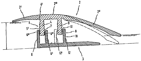
1 S Figure 1: a height-adapted bridging device in a side view.
Figure 2: a height-adapted bridging device in the invention-specific
form as a wall border in the upper position.
Figure 3: the device as per figure 2 in the lower position.
Figure 4: a bridging device for bridging a joint between same-height
floor coverings, such as laminated or parquet floors, in the upper position.
Figure 5: the device as per figure 4 in the lower position.
Figure 6: a base element.
Figure 7: an invention-specific bridging device with an alternative
base profile.
Figure 1 shows the invention-specific bridging device. In essence it
consists of an upper element 2 and a base element 3. In the implementation
example
depicted, upper element 2 has cover wings 2' and 2" of differing width, which
extend
to both sides of a middle section 2"'. Beneath middle section 2" in the
implementation
example depicted, a retaining bar 4 is attached. In the angle between
retaining bar 4
and side wing 2', a bending channel 4' is configured. Retaining bar 4 is held
by two
bars 6, 6' that project upward, which are attached elastically to base element
3. For
holding, a holding device 5, is placed both on the retaining bar 4 and on the
retaining


CA 02296564 2004-11-12
-3-
bars 6, 6' which point upwards.
In the implementation example depicted, the holding device consists of
a multiplicity of grooves 5' in retaining bar 4 which essentially run parallel
in the
longitudinal direction of the bridging device which engage into projections 6"
of
retaining bars 6, 6'.
One particular feature is that retaining bars 6, 6' are of differing
heights, and the resulting offset arrangement of retaining projections 6".
This
measure, and the insertion slant 7, allow retaining bar 4 to be put on with
great ease.
A support device 8 is depicted from a perspective in the direction of
the wider cover wing 2". Support device 8 has a retaining bar 9 which is
placed at a
distance from retaining bar 4 in the transition area between the middle
section 2"' and
the lateral wing 2", beneath the upper element. With this retaining bar 9 is
combined a
force uptake piece 10, which in the embodiment example depicted is configured
as a
bar 12. Force transfer is accomplished through a toothed device 11.
In Figure 1, the outlines of the wider wing 2" are depicted as both
dashed and continuous. Normally the continuous-line setting is the
configuration as
installed. The dashed-line of side wing 2" represents the delivered
configuration
which the upper element maintains when it is in the highest position. After
installation, the blade assumes the continuous-line position, which can also
be
designated as the lower setting. To assume this position, the upper element is
beaten
down in the area of bar 4 with a hammer and a wooden support (impact block).
This
can lead to tipping which is absorbed by the holding device. As soon as blade
2' rests
on the left-side surface, the seating process is complete, with the particular
thickness
of the left-side surface being taken into account at all points.
Figures 2 and 3 show that the device is adjustable on floor coverings
that have differing thicknesses. In Figure 2, the uppermost position, and in
Figure 3,
the lowest position, a bridging device for bordering on walls is depicted,
whereby the
retaining bar 15 becomes a support apparatus at the wall. In addition,
however, if
used at sills or platforms, it also serves as a cover, to largely hide from
view the base
element 3 which may be of a different color.
Figure 4 (uppermost position) and Figure S (lowest position) depict a
bridging device which is suited for use in joints between floor coverings at
the same


CA 02296564 2004-11-12
-4-
level, especially for bridging over expansion joints 16 in larger laminate or
parquet
floors.
Figure 7 shows a base element in detail. Figure 7 shows a further
embodiment example of the invention-specific bridging device. Here, the base
element is equipped with a corrugated projection 13, whereby the corrugation
is
rectangular. On each outer edge of the corrugation, provision has been made of
projections for the holding devices or toothed devices 11 for the support
device. In
one such base rail, a supporting moment is provided when the longer cover wing
2" is
hammered downward, as is required in certain joint configurations.
Provision can also be made in the implementation shape according to
Figure 1 to place the 12' bar, not on the side as shown, but on the other side
of bar 9.
The depiction in the drawing is configured for laminated floors with
thicknesses
between 6 and 11 mm; the same principle holds true for parquet floors between
11
and 16 mm thick. Only where the height differences to be bridged are greater
are
these devices designed to be larger.
Although preferred embodiments of the present invention have been
described, those of skill in the art will appreciate that variations and
modifications
may be made without departing from the spirit and scope thereof as defined by
the
appended claims.

Representative Drawing
A single figure which represents the drawing illustrating the invention.
Administrative Status

For a clearer understanding of the status of the application/patent presented on this page, the site Disclaimer , as well as the definitions for Patent , Administrative Status , Maintenance Fee  and Payment History  should be consulted.

Administrative Status

Title Date
Forecasted Issue Date 2005-09-06
(86) PCT Filing Date 1998-06-30
(87) PCT Publication Date 1999-01-14
(85) National Entry 2000-01-04
Examination Requested 2001-11-16
(45) Issued 2005-09-06
Deemed Expired 2018-07-03

Abandonment History

There is no abandonment history.

Payment History

Fee Type Anniversary Year Due Date Amount Paid Paid Date
Registration of a document - section 124 $100.00 2000-01-04
Application Fee $300.00 2000-01-04
Maintenance Fee - Application - New Act 2 2000-06-30 $100.00 2000-01-04
Maintenance Fee - Application - New Act 3 2001-07-02 $100.00 2001-05-22
Request for Examination $400.00 2001-11-16
Maintenance Fee - Application - New Act 4 2002-07-01 $100.00 2002-06-17
Maintenance Fee - Application - New Act 5 2003-06-30 $150.00 2003-06-30
Maintenance Fee - Application - New Act 6 2004-06-30 $200.00 2004-05-31
Maintenance Fee - Application - New Act 7 2005-06-30 $200.00 2005-05-24
Final Fee $300.00 2005-06-21
Maintenance Fee - Patent - New Act 8 2006-06-30 $200.00 2006-05-24
Maintenance Fee - Patent - New Act 9 2007-07-02 $200.00 2007-05-28
Maintenance Fee - Patent - New Act 10 2008-06-30 $250.00 2008-05-23
Maintenance Fee - Patent - New Act 11 2009-06-30 $250.00 2009-06-22
Maintenance Fee - Patent - New Act 12 2010-06-30 $250.00 2010-06-17
Maintenance Fee - Patent - New Act 13 2011-06-30 $250.00 2011-06-16
Maintenance Fee - Patent - New Act 14 2012-07-02 $250.00 2012-06-15
Maintenance Fee - Patent - New Act 15 2013-07-02 $450.00 2013-06-17
Maintenance Fee - Patent - New Act 16 2014-06-30 $450.00 2014-06-16
Maintenance Fee - Patent - New Act 17 2015-06-30 $450.00 2015-06-19
Maintenance Fee - Patent - New Act 18 2016-06-30 $450.00 2016-06-21
Owners on Record

Note: Records showing the ownership history in alphabetical order.

Current Owners on Record
HERM. FRIEDRICH KUNNE GMBH & CO.
Past Owners on Record
KEMPER, HANS A.
SONDERMANN, FRANK
Past Owners that do not appear in the "Owners on Record" listing will appear in other documentation within the application.
Documents

To view selected files, please enter reCAPTCHA code :


To view images, click a link in the Document Description column. To download the documents, select one or more checkboxes in the first column and then click the "Download Selected in PDF format (Zip Archive)" or the "Download Selected as Single PDF" button.

List of published and non-published patent-specific documents on the CPD .

If you have any difficulty accessing content, you can call the Client Service Centre at 1-866-997-1936 or send them an e-mail at CIPO Client Service Centre.


Document
Description 
Date
(yyyy-mm-dd) 
Number of pages   Size of Image (KB) 
Representative Drawing 2000-03-15 1 9
Abstract 2000-01-04 1 57
Description 2000-01-04 4 176
Claims 2000-01-04 1 41
Drawings 2000-01-04 4 85
Cover Page 2000-03-15 1 49
Abstract 2000-02-10 1 15
Description 2000-02-10 4 174
Claims 2000-02-10 1 41
Drawings 2000-02-10 4 81
Abstract 2000-02-11 1 15
Description 2000-02-11 4 174
Claims 2000-02-11 1 41
Drawings 2000-02-11 4 81
Claims 2004-11-12 1 37
Description 2004-11-12 4 193
Representative Drawing 2005-01-21 1 12
Cover Page 2005-08-12 1 42
Correspondence 2000-02-22 1 2
Prosecution-Amendment 2000-02-10 11 342
Assignment 2000-01-04 5 173
PCT 2000-01-04 17 574
PCT 2000-01-05 4 125
Assignment 2000-07-24 2 90
Prosecution-Amendment 2001-11-16 1 51
Prosecution-Amendment 2002-02-11 1 30
Correspondence 2005-06-21 1 48
Prosecution-Amendment 2004-05-11 2 69
Fees 2004-05-31 1 55
Prosecution-Amendment 2004-11-12 7 300