Note: Descriptions are shown in the official language in which they were submitted.
CA 02296580 2000-O1-04
WO 99/02203 PCT/US98/13883
AN APPARATUS AND METHOD FOR REMOVING
A LODGED MASS FROM AN ANIMAL AIRWAY
Background of the Invention
This invention relates generally to the field of surgical
instrumentation and procedure, and more particularly to an
improved device and procedure for removing obstructions,
usually large particles of food, which have accidentally
become lodged in the animal airway to cause choking.
A common cause of choking or obstruction of the human
airway is from food or other foreign objects lodged in the
back of the throat above or below the epiglottis. If the
obstruction is not removed promptly from the airway of the
victim, death due to suffocation can occur in a matter of a
few minutes.
In common manual emergency techniques, such as back
slapping (back blows), chest thrust, or the Heimlich maneuver,
the back blows, or the compressions of the chest or the
diaphragm, are to cause the pressure inside the lungs to
increase to a value greater than the atmospheric pressure
which exists above the lodged bolus in the mouth cavity. The
difference in pressure between the two sides of the bolus
causes an upward force acting on the bolus. This force, if
large enough, should overcome the restricting forces that are
produced by the throat wall.
Even though these manual techniques have saved many
lives, they are not always effective and each one has its
deficiencies. For instance, back slapping may further
complicate the situation by causing a partial obstruction to
CA 02296580 2000-O1-04
WO 99/02203 PCT/US98/13883
- 2 -
become a complete blockage or the Heimlich maneuver, which
since 1985 has been recommended by the Surgeon General as the
most effective method that should be used on choking victims,
if performed incorrectly, may result in fractured ribs or
damaged internal organs. Furthermore, the prior art
literature indicates that pressure differential created by
these methods is on the order of 0.5 psi. This pressure
differential is often insufficient for the removal of a
tightly lodged object.
In addition to the manual techniques referred to above,
a number of mechanical devices for the removal of the lodged
bolus from the airway of the choking victim have been
patented. In this approach, a pressure difference between the
two sides of the bolus is created by lowering the pressure
inside the mouth cavity (above the bolus) to a pressure less
than the pressure in the lungs. Prior mechanical devices are
described in U.S. Patent Nos. 3,946,736 (Neward), No.
4,662,367 (Gore), No. 4,790,818 (DeLuca) and U.S. Patent No.
4,971,053 (Tarrats).
In general, there are at least four conditions that are
considered essential to maximize the chance for the successful
removal of an obstructing object from the airway of the
victim.
1. The upward force created due to the pressure
differential across the obstructing object must be
large enough to overcome the frictional forces
between the object and the area of lodgement.
CA 02296580 2000-O1-04
WO 99/02203 PCT/US98/13883
- 3 -
2. The applied pressure difference should be retained
until the object is completely dislodged, i.e. an
' initial high pressure differential pulse alone may
not be sufficient for the removal of the object.
3. The creation of the initial high pressure
differential across the object should be sudden and
instantaneous, i.e, a gradual build up of the
pressure differential is not favored.
4. Since the pressure differential is created by the
evacuation of the mouth cavity (mechanical device
applications), the device must seal about the mouth
and the nostril of the victim.
As mentioned earlier, in the case of the back slapping
and Heimlich techniques, the created pressure differential is
of the order of 0.5 psi. Furthermore, in these techniques,
the duration of the applied pressure differential is
relatively short.
Neward's device, called Throat-E-Vac, comprises a hand
operating vacuum pump, a mouthpiece, a hollow tongue
depressor, and a nose clamp. This device is capable of
creating a high pressure differential and meets conditions 2
and 4, however, it does not meet condition 3, for reason that
the creation of the vacuum is gradual instead of being
. instantaneous.
Gore's invention comprises a tube-like device that is
inserted in the victim's throat enclosing the larynx area at
one end, while the rescuer sucks on the other end in an
attempt to remove the lodged bolus. A filter is also provided
CA 02296580 2000-O1-04
WO 99102203 PCT/US98/13883
- 4 -
within the tube to absorb the liquid flowing through the tube.
This device poorly meets conditions 1, 2 and 3.
DeLuca's invention comprises a hollow tongue depressor
element, a high pressurized air canister, a manually activated
valve and a jet tube orifice placed within an outer tube
shell. This device is based on the principle of indirect
suction, i.e., by positioning the free end of the tongue
depressor in the throat of the victim and opening the valve,
a sudden jet of air shoots out from the canister through the
jet tube orifice. This jet stream causes a secondary flow
through the tube shell resulting in creating a vacuum within
the mouth cavity. Even though this device is capable of
creating a relatively high pressure differential in a short
period of time, it does not meet conditions 2 and 4.
Tarrats' invention comprises a piston-cylinder mechanism
loaded with a spring, a mask and an airway tube which extends
from the mask into the victim's mouth. The principle of
operation of this device is very similar to that of Neward's
device, namely, like Neward's hand-operating vacuum pump, this
device also uses a piston and cylinder arrangement for
creating of vacuum. Tarrats' device, however, seems heavier
and mechanically more complex and difficult to operate.
Summary of Invention
Briefly stated, the invention is an apparatus and method
for dislodging an article, be it a bolus or other mass, from
an animal breathing passage. This.apparatus comprises a
puncturable, pre-evacuated canister, a release valve, a mask
CA 02296580 2000-O1-04
WO 99/02203 PCT/US98/13883
- 5 -
which seals the victim's oral and nasal cavities, a hollow
tongue depressor, the mask being mounted on the tongue
depressor and non-collapsible conduit means for connecting the
canister and the mask to the release valve.
The method of the subject invention involves instantly
exposing the oral cavity through valved conduit means to a
vacuum reservoir. This, in contrast to systems wherein a
lowered pressure is developed in the oral cavity through a
venturi created vacuum or a vacuum pump.
In the method of this invention the free end of the
tongue depressor is disposed in the throat of the victim and
with the mask in sealing position over the victim's oral and
nasal cavities, the evacuated canister is punctured. The
release valve is then opened to thereby communicate the
interior of the canister and the oral cavity of the victim to
effect an instantaneous vacuum within the oral cavity. The
vacuum condition is sustained in the oral cavity until the
bolus or other undesired mass is completely dislodged. For
the method of this invention, it is not critical that the free
end of the tongue depressor be first placed in the mouth of
the victim. The order of steps may be reversed and the
evacuated canister first punctured and then the tongue
depressor placed into the oral cavity with the mask sealing
the nasal and oral cavity. What is important is that the
release valve allowing the communication of the oral cavity
and the evacuated canister not be opened until the apparatus
is placed in a sealing position against the nasal and oral
cavities. Moreover, it is important in carrying out the method
CA 02296580 2000-O1-04
WO 99/02203 PCT/US98/13883
- 6 -
of the invention that the nasal and oral cavities be
effectively sealed in order to maximize the pressure
differential on each side of the bolus or lodged object in the
throat cavity.
It should also be mentioned that, for many of the above-
described prior art systems, the vacuum is created at the
site, while, as will be described more fully in the next
section, in the invention presented here, the vacuum is
brought ready to the site. This not only shortens the
operating time, but also eliminates the need for having many
of the above-mentioned mechanical parts, such as a piston,
cylinder, spring, orifice, hand pump, etc., needed for the
creation of the vacuum at the site.
Brief Description of the Drawing
Fig. 1 is a schematic of the apparatus of the invention.
Fig. 2 is a partial section of a release valve disposed
in the neck of the canister.
Fig. 3 is a schematic of the test model apparatus used to
obtain the data of Figure 4.
Fig. 4 is a graph comparing the apparatus of this
invention with prior art devices.
Fig. 5 is a schematic of the test model apparatus used to
obtain the data of Figure 6.
Fig. 6 is a graph plotting the pressure against time for
various weights.
CA 02296580 2000-O1-04
WO 99/02203 PCT/US98/13883
Fig. 7 is a cross section of the preferred embodiment of
the tongue depressor.
Detailed Description of the Invention
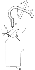
In accordance with the invention and as shown in Fig. 1,
the device, generally referred to as 10, comprises broadly:
an evacuated canister 12, a puncture member, generally
designated as 14, disposed in the opening 26 of the canister
12, and a hollow tongue depressor 16 having mounted thereon a
sealing mask 18, which mask 18 is designed so as to seal the
victim's oral and nasal passages (not shown) upon application
of the mask to the victim. Suitable conduit means 20 connect
at one end to the outlet 22 of the puncture member 14 and at
the other end to the tongue depressor 16. Disposed in the
conduit means 20, intermediate the canister 12 and the tongue
depressor 16 is a release valve 24; the function of the
release valve 24 when in an open position being to provide a
through conduit from the oral cavity (not shown) of the victim
to the interior of the evacuated canister and thereby create
a low pressure zone in the oral cavity above the lodged bolus
by having a significant portion of the air above the bolus
evacuated to the interior of the canister through pressure
equalization. A pressure indicating means 25 may be connected
to the interior of the canister 12 to show the degree of
evacuation of the canister 12.
Fig. 2 shows an embodiment of the puncture member 14
connected to the canister 12 at the neck opening 26. A thin-
walled, puncturable cup-like member 28 is seam rolled in a
CA 02296580 2000-O1-04
WO 99/02203 PCT/US98/13883
_ g _
conventional manner to the bead 30 of the canister 12.
Disposed within and fractionally fitted within the cup-like
member 28 is a guide 32 having a central opening 34 adapted to
receive the puncture member, generally designated as 14. The
puncture member 14 has a hollow shaft 37 having a central
opening 36, the leading edge of the hollow shaft 37 being
tapered at a 45° angle to provide a puncturing edge 39 for the
shaft 37, which fractionally fits within the central opening
34 of the guide 32 and is advanced against the base 38 of the
cup-like member 28. The opening 36 of the hollow shaft 37
extends at its end distal to the cup-like member 28 into and
is integral with a body portion 40; the opening 36 in the
hollow shaft 37 extending into and through the body portion 40
to a side opening 44. To aid in applying sufficient force to
the puncture member 14 to rupture the base 38 of the cup-like
member 28, a platform 46 is disposed above the body portion 40
through a shaft 48 extending from the top 50 of the body
portion 40. A handle 52 may be affixed to the platform 46 by
conventional means. Non-collapsible, flexible tube 54 is
anchored to the bead 30 of the container 12 and to the
puncture member 14 to isolate the hollow shaft 36 from the
ambient surroundings, thus maintaining the vacuum and allowing
flexing of the puncture member during the movement of puncture
member 14 toward the base 38.
While a specific embodiment of a puncture member has been
described, it will be apparent to those skilled a.n the art
that other puncture structures may be utilized. What is
essential is that the evacuated canister may be promptly and
CA 02296580 2000-O1-04
WO 99/02203 PCT/US98/13883
_ g _
readily accessed while maintaining the isolation of the
interior of the evacuated canister from ambient atmosphere.
To use the apparatus of this invention, the operator may
insert the tongue depressor 16 into the oral cavity (not
shown) of the victim and place the mask 18 against the
victim's face so as to seal the oral and nasal cavities of the
victim against the ambient environment. The puncture member
14 is forced against the cup-like member 28 to rupture the
base 38 and thereby provide a communication between the
interior of the canister 12 and the upstream side of the
release valve 24. At this point, the release valve 24 is
opened with the consequence that air is evacuated from the
oral cavity and associated throat area above the lodged bolus
thereby effecting an instantaneous and sustained pressure drop
above the lodged bolus and a significant pressure differential
on each side of the bolus which will overcome the forces of
weight and frictional engagement between the bolus and the
contiguous tissue against which the bolus is lodged and
thereby move the bolus into the mouth for removal or other
disposition.
Alternatively, the evacuated canister may be first
punctured and then the tongue depressor and mask fitted to the
victim; it being important that the release valve not be
opened until such time that the tongue depressor and mask are
in place.
The preferred embodiment of the tongue depressor, as
shown in Figure 7, is described hereafter. As shown in Figure
l, the apparatus of this invention includes a hollow tongue
CA 02296580 2000-O1-04
WO 99/02203 PCT/US98/13883
- 10 -
depressor 16. In Figure 7, the tongue depressor is generally
designated as 16. The tongue depressor 16 comprises a hollow,
rectangularly shaped member 70 having a substantially
straight, open-end portion 72 for insertion into the posterior
pharynx zone of a human, a curvilinear portion 74 extending
from the terminus of the open-end portion 72, distal to the
open-end 76, to the lip engaging annular flange portion 78,
and a tubular portion 80, extending beyond the annular flange
portion 78, which tubular portion is designed to attach to the
conduit means 20 of Figure 1. The annular flange 76 may form
a portion of the mask 18 (not shown) of Figure 1, which mask
seals the oral and nasal cavity of the victim.
To properly position the tongue depressor within the
posterior pharynx zone of an adult, the length of the tongue
depressor from the open-end 76 side of the annular flange 78
to the open-end 76 is 16.5 centimeters. The dimension of the
rectangular-shaped member is two (2) centimeters by one (1)
centimeter.
The tongue depressor controls the holding of the tongue
to the floor of the mouth by pressing the two (2) centimeter
surface against the tongue. The substantially straight
portion 72 permits the open-end 76 to be disposed above the
site of the obstruction and posterior to the epiglottis.
The apparatus of this invention was tested under various
operating conditions (Tests No. 1-3). The results are
hereafter presented and discussed.
Test No. 1 shows the degree of vacuum (pressure
differential) that can be produced in the oral cavity for the
CA 02296580 2000-O1-04
WO 99/02203 PCT/US98/13883
- 11 -
devices of this invention, the device of the DeLuca patent and
the device of the Neward patent. Prior to the test, the
device of this invention was pre-evacuated to about one psi
and DeLuca's device was pressurized up to 200 psi. The Neward
device is a hand-pump evacuation apparatus. A 142 ml plastic
jar was used to simulate the mouth cavity. The results are
shown in Fig. 4 as vacuum pressure versus time. It can be
seen from Fig. 4 that the device of this invention can produce
as much as a 12 psi vacuum pressure drop, while the DeLuca
device produces only about a momentary 5 psi pressure drop in
the oral cavity and the Neward device a 6 psi drop over time.
Also, and unexpectedly, note that for the device of this
invention, the reduced pressure is sustained over a protracted
period. Therefore, with regard to favorable dislodgement
conditions 1 and 2, mentioned above, the device of this
invention is clearly superior to the DeLuca device.
Even though the Neward device shows the capability of
producing a greater vacuum pressure differential than the
DeLuca device, the Neward apparatus and process is time
consuming and gradual and, accordingly, it does not meet the
dislodgement condition 3 mentioned above. Further, it is
again noted that for manual techniques, such as back slapping
or the Heimlich maneuver, the pressure differential created
across the object is on the order of 0.5 psi. Consequently,
the device of the invention will be quite useful for
situations where the required pressure differential for the
removal of the lodged object substantially exceeds the
capability of the manual techniques.
CA 02296580 2000-O1-04
WO 99/02203 PCT/US98/13883
- 12 -
A schematic of the experimental equipment is set forth in
Figure 3.
Test No. 2 measures the maximum upward force that the
device of this invention will exert on the lodged object. In
this test, the 142 ml plastic jar was modified by addition of
a 3/4 inch diameter pipe to the bottom of the jar to simulate
the human airway. Different weights were tested and the
results are shown in Figure 6. The maximum weight lifted by
the device was 5.2 lbs, which should be quite sufficient to
remove the obstructing object from the airway.
A schematic of the testing equipment for Test No. 2 a.s
shown in Figure 5.
Test No. 3 was carried out to determine if the device of
this invention will remove a piece of frankfurter lodged in a
simulated airway using a dummy and a face mask. In this test,
the frankfurter piece placed inside the 3/4-inch-diameter pipe
created a complete blockage. A hose then was connected from
the mouth of the dummy through its head to the jar. The face
mask was placed over the dummy's mouth and nose and the
release valve was opened. Instantly, the frankfurter piece
flew out of the pipe.
4rhile the present invention has been described by way of
preferred embodiment, it is to be understood that this
description is for illustration purposes only and the
invention should not be limited thereto, but only by the scope
of the following claims.