Note: Descriptions are shown in the official language in which they were submitted.
CA 02296801 2000-O1-24
CABLE AND HEAT SINK
BACKGROUND OF THE INVENTION
The present invention relates to a cable capable of radiating heat, and in
particular, to a
cable that is connected to, for example, a portable computer to transmit image
signals displayed
to users and to conduct heat generated inside the portable computer to its
exterior for heat
l0 radiation.
The present invention also relates to a heat sink using the cable capable of
radiating heat,
and in particular, to a heat sink that radiates heat by conducting heat to the
cable capable of
radiating heat from a CPU in a portable computer, which is a heat generator
from which heat
cannot be radiated easily and to which a radiator cannot be attached easily.
BACKGROUND ART
For example, "Nikkei Electronics 11 Jan. pp. 83 to 95 (Document 1; Nikkei BP
Co., Ltd.,
published on 11 Jan. 1999, No. 734)" discloses a small computer that is
conveniently portable
(so-called "wearable computer").
2 0 The body of the wearable computer has a small external shape, for example,
190 % 63
117 (mm; Document 1, p. 90), and such a computer is fixed to a user's belt for
operation to
realize a high mathematical performance.
In addition, the wearable computer has, for example, a display device
connected to the
body of the wearable computer via a cable and mounted on the user's head and
an input device
JP9-1999-0027 1
CA 02296801 2000-O1-24
that can be operated one-handed.
As described above, the wearable computer is configured to have a very small
body, and it
is difficult to externally attach a radiator to the wearable computer due to
its installation on the
user's body (clothes).
On the other hand, since a high mathematical performance is required of the
wearable
computer, the reduction of the heating value is limited that is attempted by
maintaining a lower
clock frequency. Thus, the heat radiation design of the wearable computer is
very difficult.
For example, Published Unexamined Patent Application No. 09-288913 (Document
2)
discloses a flat cable for power including recesses and projections on its
sides to radiate heat
l0 from the cable.
This flat cable effectively radiates heat from itself, but cannot be used for
an application in
which heat is allowed to escape to the exterior from a device to which the
flat cable is connected.
Problems to be solved by the invention
The present invention has been provided in view of this problem of the
background art, and
an object of this invention is to provide a cable capable of conducting heat
generated inside a
connected device to the exterior for heat radiation.
Another object of this invention is to provide a heat sink capable of using a
cable
connected to a device to which a radiating means cannot be attached easily in
order to conduct
2 0 heat generated inside this device to the exterior for heat radiation.
A specific object of this invention is to provide a cable and heat sink
wherein a heat
conducting member is added to a cable connecting the body of a portable
computer such as a
JP9-1999-0027 2
CA 02296801 2000-O1-24
wearable computer to a display device and wherein the cable with the heat
conducting member
added thereto is used to radiate heat from the interior of the portable
computer body.
SUMMARY OF THE INVENTION
Cable
To achieve these objects, a first cable according to this invention is a cable
capable of
radiating heat, comprising a heat conducting and radiating member for
conducting heat in the
longitudinal direction of the cable and radiating the conducted heat.
Preferably, the cable comprises conductors extending in the longitudinal
direction of the
l0 cable, and the heat conducting and radiating member extends in the
longitudinal direction of the
cable and disposed along the conductors.
Preferably, the conductor is a transmission line that transmits signals or
power.
In addition, a second cable according to this invention is a cable capable of
radiating heat
comprising conductors extending in the longitudinal direction of the cable, a
heat conducting and
radiating member covering the circumference of the conductors to conduct heat
in the
longitudinal direction of the cable and to radiate the conducted heat, and a
coating covering the
circumference of the heat conducting and radiating member.
The cable according to this invention, for example, connects the body of a
wearable
computer and its display device together and conducts to the exterior, heat
generated by a CPU in
2 0 the body of the wearable computer to release the conducted heat to the
exterior from the surface
in order to radiate heat from the interior of the body.
In the cable according to this invention, the heat conducting and radiating
member is, for
JP9-1999-0027 3
CA 02296801 2000-O1-24
example, a heat conducting sheet wound between signal lines and a coating of
the cable to
conduct in the longitudinal direction of the cable, heat generated by the CPU
in the computer
body in order to gradually radiate heat from the surface of the cable.
Heat sink
In addition, a heat sink according to this invention comprises a cable capable
of radiating
heat, and a heat connecting member for thermally connecting a heat generator
to the cable
capable of radiating heat.
A heat sink according to this invention uses the above cable according to this
invention to,
l0 for example, conduct heat generated by the CPU inside the computer body, to
the exterior for
heat radiation.
The heat connecting means comprises, for example, a heat pipe for thermally
connecting
together the CPU inside the wearable computer and the heat conducting and
radiating member
(the above heat conducting sheet) of the cable according to this invention
used as a cable for
connections to a display device. The heat connecting means conducts heat
generated by the CPU
to the heat conducting sheet of the cable in order to help to radiate the heat
generated by the CPU
to the exterior.
ADVANTAGES OF THE INVENTION
2 0 As described above, the cable according to this invention can conduct heat
generated in a
connected device to the exterior for heat radiation.
In addition, the heat sink according to this invention can use the cable
connected to a
JP9-1999-0027 4
CA 02296801 2000-O1-24
device for which a radiating means cannot be provided easily in order to
conduct heat generated
inside this device to the exterior for heat radiation.
In addition, the cable and heat sink according to this invention is suitable
for heat radiation
from the interior of a portable computer such as a wearable computer effected
using the cable
that connects the body of the portable computer and a display device and to
which the heat
conducting member is added.
Brief Description of the Drawings:
Figure 1 shows a configuration of a wearable computer to which a cable and
heat sink
according to this invention is applied;
Figure 2 shows a configuration of the cable shown in Figure 1;
Figure 3 is a sectional view of the cable shown in Figures 1 and 2;
Figure 4 shows a connection between a PC body and a cable;
Figure 5 shows a connection between the cable and a connection member, which
is shown
by circle (a) in Figure 4;
Figure 6 shows a connection between a CPU and a heat collecting member, which
is
shown by circle (b) in Figure 4; and
Figure 7 is heat radiation effected by the cable according to this invention.
2 0 SUMMARY OF THE INVENTION
Preferred embodiment
Embodiments of this invention will be described below.
JP9-1999-0027 5
CA 02296801 2000-O1-24
Wearable computer 1
First, Figure 1 is referenced to describe a wearable computer 1 to which a
cable and heat sink
according to this invention is applied.
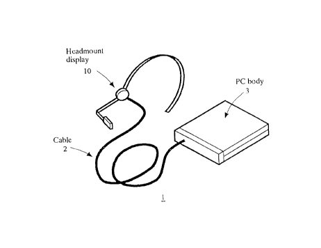
Figure 1 illustrates a configuration of the wearable computer 1 to which the
cable and heat
sink according to this invention is applied.
As shown in this figure, the wearable computer 1 comprises a headmount display
10, a
cable 2, and the body (PC body) 3 of the wearable computer.
In the wearable computer l, the cable 2 according to this invention connects
together the
PC body 3 and the headmount display 10 mounted on the user's head to transmit
an operating
1 o power and image signals from the PC body 3 to the headmount display 10
while conducting heat
generated by a CPU 30 (that will be described in detail with reference to
Figure 4) inside the PC
body 3 to the exterior of the PC body 3 to release it from the surface,
thereby radiating heat from
the interior of the PC body 3.
As described below, besides the configuration of the cable 2 as a signal and
power cable
for transmitting signals and power, the cable 2 can be configured, for
example, as a power or
signal cable for transmitting power or signals, or as a loss prevention rope
that does not have
power or signal lines and that simply connects the headmount display 10 and
the PC body 3
together. For simple description and easy understanding, the following
description explains a
specific example in which the cable 2 is configured as a signal cable as
described above, unless
2 0 otherwise stated.
Configuration of the cable 2
JP9-1999-0027 6
CA 02296801 2000-O1-24
A configuration of the cable 2 will be described below.
Figure 2 shows a configuration of the cable 2 shown in Figure 1.
Figure 3 is a sectional view of the cable 2 shown in Figures 1 and 2.
As shown in Figures 2 and 3, the cable 2 extends in the longitudinal direction
of the cable 2
and is composed of conductors 24 transmitting an operating power and image
signals from the
PC body 3 to the headmount display 10, a heat conducting sheet 22 provided
along the
conductors 24 so as to cover their circumference, and a coating 24 provided so
as to cover the
conductors 24 and the heat conducting sheet 22 in order to protect the
interior of the cable 2.
That is, the cable 2 is configured to have the heat conducting sheet 22
between the
l0 conductors 24 and coating 20 of a normal signal cable.
Heat conducting sheet 22
The heat conducting sheet 22 is composed of a material having a high heat
conductivity
and flexibility, for example, the product of Matsushita Electric Industrial
Co., Ltd. "Panasonic
Graphite Sheet". The heat conducting sheet 22 conducts in the longitudinal
direction of the cable
2, heat generated by the CPU 30 inside the PC body 3 while gradually releasing
the heat from the
surface of the cable 2 in order to radiate it from the PC body 3.
The properties that should be provided for the heat conducting sheet 22
include a high
conductivity, a high flexibility, and a high durability.
2 0 Of these properties, the high heat conductivity is required to radiate
heat from the PC body
3.
In addition, due to the connection between the PC body 3 and the headmount
display 10,
JP9-1999-0027 7
CA 02296801 2000-O1-24
the usability of the wearable computer 1 may be degraded if the cable 2 lacks
flexibility. Thus,
the heat conducting sheet 22 must be very flexible for the same reason as in
the cable 2.
Likewise, the heat conducting sheet 22 is repeatedly folded prior to use, so
it requires a
high durability equal to or higher than that of the other components of the
cable 2 (signal lines 24
and the coating 20).
Connection between the CPU 30 in the PC body 3 and the cable 2
The connection between the cable 2 and the CPU 30 in the PC body 3 will be
described
below.
Figure 4 shows the connection between the PC body 3 and the cable 2.
Figure 5 shows a connection between the cable 2 and a connection member 34,
which is
shown by circle (a) in Figure 4.
Figure 6 shows a connection between the CPU 30 and a heat collecting member
38, which
is shown by circle (b) in Figure 4
As shown in Figures 4 to 6, the CPU 30 and other parts are disposed in a card
36 inside the
PC body 3.
As shown in Figures 4 and 6, the cable 2 is led from the exterior to the
interior of the PC
body 3, and a coating 20 at the end of the cable 2 is removed to draw out the
heat conducting
sheet 22 and the conductors 24 as appropriate.
2 0 The conductors 24 are further connected to required parts of the card 36.
As shown in Figures 5 and 6, the heat conducting sheet 22 and the conductors
24 are
tightened to the card 36 together with the connection member 34 and one end of
a heat pipe 32
JP9-1999-0027 8
CA 02296801 2000-O1-24
using a screw. The heat conducting sheet 22, the connection member 34, and the
heat pipe 32 are
thermally connected together.
For example, a heat conducting pad 380 is provided on a parts side of the heat
collecting
member 38, as shown in Figure 6. When the heat collecting member 38 is mounted
on the card
36 using four screws 382-1 to 382-4, the heat conducting pad 380 is pressed
against the top
surface of the CPU 30.
In this manner, the heat collecting member 38 and the CPU 30 are thermally
connected
together via the heat conducting pad 380.
The other end of the heat pipe 32 is guided on the card 36 and locked to the
heat collecting
member 38 so as to be caulked for thermal connection.
That is, the CPU 30 and the heat conducting sheet 22 of the cable 2 are
thermally
connected together via the heat collecting member 38, the heat pipe 32, and
the connection
member 34.
Heat radiation effected by the cable 2
Heat radiation effected by the cable 2 will be described below with reference
to Figure 7.
Figure 7 shows heat radiation effected by the cable 2 according to this
invention.
As shown by the arrows in Figure 7, heat generated by the CPU 30 inside the PC
body 3 is
transferred to the heat collecting member 38 and is further transferred to the
heat conducting
sheet 22 of the cable 2 via the heat pipe 32 and the connection member 34.
2 0 The heat conducting sheet 22 conducts in the longitudinal direction of the
cable 2, the heat
transferred via the heat collecting member 38, the heat pipe 32, and the
connection member 34
while gradually releasing the heat to the exterior via the coating 20 to
radiate it from the interior
JP9-1999-0027 9
CA 02296801 2000-O1-24
of the PC body 3.
The above material of the heat conducting sheet 22 is only an example and may
be
replaced by another material having a similar heat conductivity and
flexibility depending on the
application. Instead of graphite, the heat conducting sheet may be, for
example, a material
comprising a metal having a high heat conductivity (copper or the like) which
has been shaped
like a sheet or a line.
In addition, the method for connecting the CPU 30 and the heat conducting
sheet 22
together which is shown in Figure 4 is only an example, and a different
connection method that
provides a similar heat conduction effect is applicable depending on the
application.
JP9-1999-0027 10