Note: Descriptions are shown in the official language in which they were submitted.
CA 02296876 1999-12-16
METHOD FOR PRODUCING A VARIABLE DENSITY, CORRUGATED RESIN
BONDED OR THERMO-BONDED FIBERFILL AND THE STRUCTURE
PRODUCED THEREBY
FIELD
The present invention relates to a corrugated
fiberfill structure and to a method for forming same. More
particularly, the present invention relates to a varying
density, corrugated, resin-bonded or thermo-bonded
fiberfill structure and to a method for forming same.
BACKGROUND
According to a known method, shown in Fig. 1, after
opening a bale and carding fibers to form a web A, the web
A is shaped into zig-zag lamination A' to create strength
in both longitudinal and transverse directions. This is
accomplished by sequentially conveying belts B, C, and D,
which transversely convey the web A. Belt E conveys
longitudinally, whereas conveying belts C and D
independently reciprocate transversely. After the zig-zag
lamination A' is shaped by cross-lapping, resin is sprayed
on the lamination A', thereby penetrating and bonding the
lamination A'. However, the prior process possesses the
following drawbacks:
1. The thickness of the web A' must differ with
various applications. The thickness of the lamination A'
depends on the number of single webs A present, i.e., the
manufacturing conditions must be controlled under a higher
conveying speed of conveying belts B, C and D; a higher
transverse moving speed of conveying belts C and D; and/or
a lower speed of conveying belt E. Regarding a
1
CA 02296876 1999-12-16
specification of 500 g/m2 of the bonded fiberfill, the
resulting cross angle of lamination A' is small or even
nearly zero, thereby maintaining transverse strength but,
at the same time, decreasing longitudinal strength.
Accordingly, the performance of the final product is
inferior with regard to the longitudinal strength.
2. Taking a carding web of 20 g/m2, for example, a
final product having a thickness of 500 g/m2 necessitates
25 layers of card web, thereby resulting in low
productivity, poor resin-penetration, and making it
difficult for the zig-zag lamination A' to bond together.
3. Conventional resin-bonded fiberfill only provides
strength with respect to the transverse and longitudinal
directions but lacks three-dimensional strength. Therefore,
the final products possess poor anti-compression
properties, etc.
Some other conventional measures related to production
of corrugated fiberfill structures and the shortcomings
thereof are as follows:
U.S. Patent No. 4,576,853 patented to Vaughn discloses
multilayer pleated textile fiber product which is formed of
a plurality of unstable layers of textile fiber pleated
together with both the layers and the pleats in close
contact. In certain forms of the product, at least one of
the layers has properties different from those of another
layer.
U.S. Patent No. 2,689,811 patented to Frederick et al.
teaches corrugated fibrous battings which are wave
structure, possessing weak longitudinal strength, rough
surface and single density. Such product has a thickness
less than 1.5 inches.
2
CA 02296876 1999-12-16
U.S. Patent No. 2,428,709 patented to R. F. Halvaty
provides lappers and conveyors for forming corrugation by
differential speeds so as to produce low thickness and low
density batting.
U.S. Patent No. 1,988,843 patented to Heldenbrand
employs a plurality of cellular structure sheet materials
for mattresses or cushions. The cellular structure sheet
materials are coated and united at their points of contact
with a resilient flexible glue.
U.S. Patent No. 4,111,733 patented to G. Periers
utilizes a series of horizontal differential speed belts to
manufacture an undulating or corrugated longitudinal
material. The thickness of the corrugation is limited
between two longitudinal walls usually to no more than 1.5
inches since the material is bunched up by differential
speeds.
U.S. Patent No. 2,219,737 patented to Tokihito
discloses a cushion material which is formed by needling a
pile of staple fiber to form a flat batt and folding the
batt to form corrugation, and then sewing, bonding or
welding together.
EAP 350,627 discloses a device for forming carded web
into perpendicularly laid bulky fiber sheets by either
rotating or vibrating a comb having needles thereon to
bunch the carded web up from a horizontal direction.
UK 2,077,786 discloses a mat and similar fabrics made
of textile fibers, which are mechanically treated by
carding, emery-polishing, teazling or bulking, for improved
adhesion for outer plastics layers.
All the above references fail to provide a structure
with improved smooth surface consisting of shingle or
3
CA 02296876 1999-12-16
overlapping crests web structure and a gradient density
across the thickness of the structure. Also, the above
references fail to provide a structure with improved
longitudinal strength and a thickness up to 8 inches.
Furthermore, the above references cannot provide a
different form of corrugation with a plurality of shingles
or overlapping crests at the surface portions but vertical
or substantially perpendicular in the central portions.
Therefore, it is the purpose of the present invention
to mitigate and/or obviate the drawbacks existing in the
prior art in the manner set forth below.
SUMMARY
Accordingly, it is an object of this invention to
provide a method for corrugating bonded fiberfill which
enhances three-dimensional strength and resilience of the
final product.
Another obj ect of the present invention is to provide
a method for corrugating bonded fiberfill which allows
excellent penetration of resin and hot air by means of
resin bonding or thermo-bonding, thereby resulting in
products having increased strength.
Another object of this invention is to provide an
improved structure of resin-bonded or thermo-bonded
fiberfill which possesses enhanced properties of anti-
compression and air permeability, for use in products such
as quilts, pillows, cushioned seats, cushions, mattresses,
sleeping bags, ski jackets, etc. and as filtering material.
A further object of this invention is to provide an
improved structure of resin-bonded or thermo-bonded
fiberfill which supplies an alternative thickness by
4
CA 02296876 1999-12-16
regulating the corrugated fiber web, thereby maintaining
anti-compression and air permeability.
An additional object of the present invention is to
produce a fiberfill product having a smooth and even
surface.
Yet another object of the present invention is to
provide an improved fiberfill structure in which strength
is improved in the machine direction on the surface of the
structure while retaining the vertical strength in the
remaining corrugations.
Still another object of the present invention is to
produce a corrugated fiberfill structure which may be of
low density, good stuffability, high bulk recovery when
unloaded, low bulk under load, extremely soft feel and
having a drape suitable for products such as comforters,
sleeping bags and apparel.
Other objects of the present invention include a
corrugated fiberfill structure having a soft surface and a
firm interior and a method of forming such structure.
Yet other objects include a fiberfill structure
varying in density between the surfaces of the structure
and to a method of forming such structure.
The invention is directed to a corrugated fiberfill
structure comprising one fibrous web folded to form a
plurality of pleats having alternating crests and bases,
each of the pleats having a pair of legs, each of the legs
having a first leg surface and a second leg surface, the
first leg surface of one leg being in intimate contact with
the first leg surface of an adjoining leg of the pleat and
the second leg surface of said one leg being in intimate
contact with the second leg surface of an adj oining leg of
5
CA 02296876 1999-12-16
an adjacent pleat over a portion of each leg, at least some
crests defining a first structural surface and at least
some bases defining a second structural surface, with a
distance between the first and second structural surfaces
defining a thickness of the structure, spaces being left
between contact sites of the legs, whereby the structure
has a density that varies across the thickness of the
structure, between said first and second structural
surfaces.
The invention is also directed to a method for forming
a corrugated bonded fiberfill structure having pleats, a
first surface defined by crests of at least some of the
pleats and a second surface defined by bases of at least
some of the pleats, comprising the steps of lapping at
least one fibrous web formed from first fibers and second
fibers in alternating directions to form alternating
pleats, with spaces being left between contact sites of the
pleats to form a corrugated fibrous web varying in density
between the first and second surfaces; and bonding the
pleats of said corrugated fibrous web.
Further objects and advantages of the present
invention will become apparent with the description that
follows.
BRIEF DESCRIPTION OF THE DRA~nIINGS
Fig. 1 is a perspective view of a known cross-lapping
machine;
Fig. 2 is a schematic view of an apparatus for
corrugating resin-bonded fiberfill according to the present
invention;
6
CA 02296876 1999-12-16
Fig. 3 is a schematic view of an apparatus for
corrugating thermo-bonded fiberfill according to the
present invention, optionally with another two outer webs
adhering to the corrugated fiber web;
Fig. 4 is a perspective view of an improved structure
of resin-bonded or thermo-bonded fiberfill according to the
present invention;
Fig. 5 is a perspective view of an embodiment of the
present invention produced in accordance with apparatus
shown in Fig. 3;
Fig. 6 is a side view of another embodiment in
accordance with the present invention, wherein a fiber web
has a saw tooth-like corrugated arrangement;
Fig. 7 is a side view of yet another embodiment in
accordance with the present invention, wherein the fiber
web is triangularly corrugated;
Fig. 8 is a schematic view of the portion of an
apparatus for corrugating resin-bonded or thermo-bonded
fiberfill according to an embodiment of the present
invention;
Figs. 9A, 9B, 9C and 9D show various embodiments of
the brushing device illustrated in Fig. 8;
Fig. 10 is a perspective view of the fiberfill
material produced with the apparatus of Fig. 8;
Fig. 11 is an enlarged portion of the region of the
fiberfill product illustrated in Fig. 10 at the peaks of
the fiberfill portion;
Fig. 12 is a side view of an embodiment of the
corrugated fiberfill structure of the invention having low
density regions adjacent the surfaces of the structure and
a medium density region therebetween;
7
CA 02296876 1999-12-16
Fig. 13 is a side view of another embodiment of the
corrugated fiberfill structure of the invention having a
low density region adjacent one surface of the fiberfill
structure with the remaining portion of the structure
having a high density;
Fig. 14 is a side view of an embodiment of the
corrugated fiberfill structure of the invention having a
high density region intermediate a low density region and a
medium density region;
Fig. 15 is a side view of an embodiment of the
corrugated fiberfill structure of the invention similar to
that of Fig. 13 but in which the thickness of the structure
varies over its length;
Fig. 16 is a side view of another embodiment of the
corrugated fiberfill structure of the invention similar to
Fig. 15 but in which neither opposing surfaces is flat and
having a high density region intermediate two low density
regions;
Fig. 17 is a side view of an embodiment of the
corrugated fiberfill structure of the invention similar to
Fig. 12 but formed from two engaging pleated webs;
Fig. 18 is a side view of another embodiment of the
corrugated fiberfill structure of the invention similar to
Figs. 13 and 17;
Fig. 19 is a side view of an embodiment of the
corrugated fiberfill structure of the invention formed from
three engaging pleated webs;
Fig. 20 is a side view of another embodiment of the
corrugated fiberfill structure of the invention similar to
Figs. 14 and 19;
8
CA 02296876 1999-12-16
Fig. 21 is a side view of another embodiment of the
corrugated fiberfill structure of the invention similar to
Fig. 19 but having a medium density region located
intermediate a low density region and a high density
region;
Fig. 22a is a side view of another embodiment of the
corrugated fiberfill structure of the invention having
projecting pleats, prior to completion of the varying
density forming process;
Fig. 22b is a side view of the embodiment of the
corrugated fiberfill structure of the invention illustrated
in Fig. 22a, after completion of the forming process;
Fig. 23a is a side view of another embodiment of the
corrugated fiberfill structure of the invention similar to
Fig. 22a having projecting crests;
Fig. 23b is a side view of the completed embodiment of
the corrugated fiberfill structure of the invention
illustrating Fig. 23a, similar to Fig. 22b, having
"shingles" on one surface;
Fig. 24a is a side view of another embodiment of the
corrugated fiberfill structure of the invention similar to
that shown in Fig. 22a but formed from two engaging pleated
webs;
Fig. 24b is a side view of the completed embodiment of
the corrugated fiberfill structure of the invention
illustrated in Fig. 24a;
Fig. 25a is a side view of another embodiment of the
corrugated fiberfill structure of the invention similar to
that shown in Fig. 22b but formed from three engaging
pleated webs;
9
CA 02296876 1999-12-16
Fig. 25b is a side view of the completed embodiment of
the corrugated fiberfill structure of the invention
illustrated in Fig. 25a;
Fig. 26 is a side view of another embodiment of the
corrugated fiberfill structure of the invention similar to
Fig. 14 with respect to density gradients but having a
somewhat arcuate configuration of the pleats;
Fig. 27 is a schematic view of a portion of an
apparatus for forming a corrugated fiberfill structure with
density gradients from a single fibrous web;
Fig. 28 is a schematic view of a portion of an
apparatus for forming a corrugated fiberfill structure with
density gradients from two fibrous webs;
Fig. 29 is a schematic view of a portion of an
apparatus for forming a corrugated fiberfill structure of
the invention similar to that of Fig. 28 but additionally
provided with brushing devices;
Fig. 30 is a schematic view of a portion of an
apparatus for forming a corrugated fiberfill structure with
density gradients from three fibrous webs;
Fig. 31 is a schematic view of a portion of an
apparatus for forming a corrugated fiberfill structure of
the invention similar to that of Fig. 30 but additionally
provided with brushing devices;
Fig. 32 is a schematic view of a portion of an
apparatus for forming a corrugated fiberfill structure
having a folded-over pleat configuration from a single
fibrous web;
Fig. 33 is a schematic view of a portion of an
apparatus for forming a corrugated fiberfill structure
CA 02296876 1999-12-16
having a folded-over pleat configuration from two fibrous
webs; and
Fig. 34 is a schematic view of a portion of an
apparatus for forming a corrugated fiberfill structure of
the invention having a folded-over pleat configuration from
three fibrous webs.
DETAILED DESCRIPTION OF THE PREFERRED EMBODIMENTS
Now referring to the drawings, initially to Fig. 2, a
preferred embodiment of an apparatus for implementing a
method for corrugating resin-bonded fiberfill in accordance
with the present invention is shown. The method proceeds as
follows.
A bale of fibers is initially opened, carded, and
formed into a fibrous web, which is indicated by reference
numeral 40. The fibrous web 40 is fed into a cross-lapping
machine 10 which laps the fiber web 40 in alternating
directions.
After leaving the cross-lapping machine 10, the
fibrous web 40 is preferably drafted by a drafting machine
15, thereby increasing the longitudinal strength thereof.
The fibrous web 40 is conveyed between a pair of parallel
spaced conveyor belts or rollers 20. The conveyor belts or
rollers 20 pivot about an axis at the entrance thereto,
(i.e., the belts or rollers are pivoting conveyor means) as
shown by the arrows in Fig. 2, so that as the fibrous web
40 exits therefrom, the pivoting motion folds the fibrous
web 40 at the laps formed by the cross-lapping machine 10,
forming a corrugated structure as the fibrous web 40 enters
a forming chamber or conveying passage 30, which typically
contains one or more pair of parallel-arranged conveyors,
11
CA 02296876 1999-12-16
such as conveyor belts. The conveying passage 30 has a
height set at a predetermined height desired for the
corrugations of the fibrous web 40 to yield the corrugated
blanket . Thus, the cooperation of the pivoting conveyor 20
and the forming chamber 30 determines the height, pitch and
orientation of the corrugations.
At this point, to the fibrous web 40, in the form of a
corrugated blanket, is optionally applied a first outer web
1, which is conveyed from a first roller 70 and then passes
into a spraying machine 50, where resin is sprayed onto one
side of the first outer web 1. Then, the fibrous web 40
having the first outer web 1 thereon is heated and dried by
an oven 60. Preferably, only a single heating step is used
in the process. After leaving the oven 60, a second outer
web 1, which is conveyed from a second roller 70, is
applied to the fibrous web 40 and the fibrous web then
passes into a spraying machine 80, where resin is sprayed
onto the second outer web 1. Again, the fibrous web 40,
having two outer webs 1 thereon, is heated and dried by the
oven 60. The resin will adhere the corrugations 21, as
shown in Fig. 5. The first and second outer webs 1 can be
optionally applied to the fibrous web 40 after passing into
the spraying machines 50 and 80, respectively.
Alternatively, products possessing no sandwich structure,
as shown in Fig. 4, can be manufactured by deleting the
step of applying the two outer webs 1 on the fibrous web
40.
Fig. 4 provides a perspective view of the product
having no sandwich structure. The fibrous web 40 possesses
strength along the three-dimensional axes thereof,
significantly increasing the strength and resilience of the
12
CA 02296876 1999-12-16
overall structure. Furthermore, the spaces between the
contact sites 41 and 42 of the corrugations allow resin to
be uniformly dispersed and penetrate throughout the
structure, which subsequently facilitates the drying and
curing process.
An alternate and preferred embodiment uses no resin.
When no resin is added, according to the process
schematically illustrated in Fig. 3, fibers of low melting
point (second fibers) will be blended into regular fibers
(first fibers) before the process is started. The molten
fibers bond the corrugations and the regular fibers
together. Upon cooling of the corrugated blanket, the
melted fibers solidify to strongly bond the high melting
fibers to one another as well as adjacent corrugations in
mutual contact. Before passing into the oven 60, the
corrugated fibrous web 40 is optionally sandwiched with a
pair of transversely-positioned outer webs 1, respectively
conveyed from two rollers 70. The sandwich structure passes
into the oven 60, thereby bonding the outer webs 1 on the
fibrous web 40.
The fiber source used in the practice of this
preferred embodiment of the invention is a combination of
low melting fibers and high melting fibers. The low melting
fibers should melt at a temperature of at least 20,
preferably at least 30°C below the melting temperature of
the high melting fibers.
Fibers of the same or similar material can be used for
both the low melting fibers and the high melting fibers,
depending on the particular intended use and their
combination with other fibers. For example, a polyamide
fiber having a melting point of about 250°C can be the low
13
' CA 02296876 1999-12-16
melting fiber when used in combination with aramid fibers
having a melting point of greater than 280°C (if they melt
at all); and that same polyamide fiber can be the high
melting fiber when used in the practice of this invention.
Materials from which the fibers are formed include, but are
not limited to: polyesters, such as polyethylene
terephthalate (m.p. 250°C); copolyesters, such as a
copolyester of 60-80 mole percent ethylene terephthalate
and 20-40 mole percent ethylene isophthalate (m. p. 110-
170°C); polypropylene (m. p. about 160°C); polyamides, such
as nylon 6 (m.p. 220°C) and nylon 66 (m.p. 254°C); and
aramids, such as poly(meta-phenylene isophthalamide)
(decomposes) and poly(para-phenylene terephthalamide)
(decomposes).
The low melting fibers can be of a so-called sheath-
core construction wherein there is a core component and a
lower melting sheath component. The lower melting sheath
component serves, for the purpose of this invention, as the
relatively low melting polymer.
The combination of fibers is generally 10 to 40 weight
percent low melting fibers. It has been found that a
concentration of low melting fibers which is less than 5
weight percent will not yield a strongly bonded structure;
and a concentration which is greater than 50 weight percent
will yield a structure which is stiff and has a harsh hand.
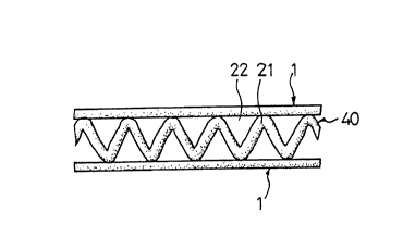
Preferably as shown in Fig. 5, corrugations 21 of the
fibrous web 40 are arranged accordion-like, where top and
bottom ends thereof are generally rounded, with respective
inner and outer spaces 22 formed between respective
corrugations 21 and the outer webs 1. Also, in accordance
with the present invention, the corrugations 21 of the
14
CA 02296876 1999-12-16
fibrous web 40 can be saw tooth-shaped or triangularly-
shaped, as respectively shown in Figs. 6 and 7.
Additional embodiments of the present invention are
illustrated in Figs. 8 to 11. These embodiments are
variations of the resin-bonded and thermo-bonded corrugated
structures and methods of making such structures described
above. Each of these modified embodiments involves brushing
peaks 23 of the corrugations 21, thereby causing fibers 45
at or adjacent the peaks 23 of the corrugations to be
pulled loose from the fibrous web 40, orient themselves
across the gaps 22 existing between the peaks 23 of the
corrugations to contact, and possibly become entwined with
the fibers 45 of the adjacent peak 23 of the fibrous web
40. The brushing step of the present invention is conducted
after the alternately lapped fibrous web is folded so as to
form a corrugated fibrous web and before either resin is
applied to the corrugated web in the formation of a resin-
bonded corrugated fibrous web or the heating step in the
formation of a thermo-bonded corrugated fibrous web.
To obtain the bridging, corrugated, fibrous webs of
the present invention, the peaks 23 are brushed once the
corrugated structure is formed. This is achieved by
locating one or more brushing apparatus or brushes 90
within the conveying passage or forming chamber 30. The
forming chamber 30 includes at least one pair of parallel-
spaced conveyors 31 at the downstream end of which is
positioned one or more brushing apparatus 90.
Preferably, as illustrated in Fig. 8, the system of
the present invention employs at least two pair of
parallel-spaced conveyors, such as conveyor belts 31, 31';
32, 32'; and 33, 33', arranged in series in the conveying
CA 02296876 1999-12-16
passage 30. Preferably, the brushing apparatus 90 is
positioned between first and second pairs of parallel-
arranged conveyors. Optionally, additional brushing
apparatus may be located intermediate successive pairs of
parallel-spaced conveyors. While each individual conveyor
in a pair of parallel-spaced conveyors, such as 31, 31';
32, 32'; or 33, 33', may be of the same length, as measured
in the direction of movement of the fibrous web 40, it is
preferred that the length of each conveyor be different.
This permits a skewed arrangement of each brushing
apparatus 90 as illustrated in Fig. 8. In such an
arrangement, while a brushing apparatus 90 is applying
force to a peak 21 on one side of the corrugated fibrous
structure, support is provided by the belt of the conveyor
on the opposite surface of the moving, corrugated fibrous
web.
Various types of brushing apparatus may be employed in
the present invention. Examples of such brushing apparatus
are illustrated in Figs. 9A to 9D. The particular type of
brushing apparatus selected and positioning with respect to
the peaks 23 of the corrugations of the fibrous web 40 are
based, at least in part, on variables such as the material
from which the fibrous web is formed, the length of the
fibers, the density of the fibrous web, how tightly the
corrugations are arranged, etc. Examples of the types of
brushes employed as the brushing apparatus 90 include
rotating brushes 91, of the type illustrated in Fig. 9A in
which radially-oriented bristles rotate about an axis.
An alternative embodiment is illustrated in the
conveyor brush 92 or Fig. 9B. In the conveyor brush 92, a
conveyor belt is provided with outwardly projecting
16
' CA 02296876 1999-12-16
bristles. The conveyor belt being mounted on and extending
between a rotating, driving wheel or pulley and a driven
wheel or pulley. Although the rotating and conveyor
brushes, 91 and 92, respectively, may be arranged so as to
rotate in the direction of movement of the corrugated
fibrous web 40, it is generally preferred that rotation
occurs in the direction opposite that of the direction of
movement of the corrugated fibrous web 40, as illustrated
by the arrows shown in Figs. 9A and 9B.
Other exemplary types of brushes suitable for use in
the present invention include the fixed brush 93
illustrated in Fig. 9C and the air "brush" 99 illustrated
in Fig. 9D. The latter type of brushing apparatus includes
one, or a plurality of nozzles oriented toward the surface
of the peaks 23 of the corrugations. As with the rotating
brush, the nozzles of the air brush 94 are preferably
oriented counter to the direction of movement of the
fibrous web 40. Air, under suitable pressure, is passed
through the nozzles in a manner to lift ends of-fibers 45
from the surface of the fibrous web 40, in a manner similar
to that achieved by the brushing devices 91 to 93. A single
difference between the air brush 94 and the brushing
devices 91 to 93 is that in addition to locating the air
brush between adjacent conveyors, such as 31 and 32, if a
conveyor is provided having the form of an open mesh, the
air brush may be located within the space defined by the
endless loop of the conveyor belt. In such an instance, air
passes through the nozzles) of the air brush 94 and
contacts the fibers 45 after passing through the open mesh
of the conveyor belt.
17
' CA 02296876 1999-12-16
As illustrated in Figs . 9A to 9D, showing the various
brushing devices in an embodiment of the process of the
present invention, and in Figs. 10 and 11, which illustrate
the fiber-bridging corrugated fibrous webs of the present
invention, it may be seen that portions of fibers 45 extend
from peaks 23 or a region of a corrugated fibrous web 40
adjacent such peaks, to adjacent corrugated peaks 23,
bridging the gaps 22 between adjacent corrugations.
In effect, the brushing frees ends of fibers 45 from
the fibrous web and "sweeps" the free ends of the fibers to
adjacent peaks of the corrugated web. While freeing one end
of a fiber to bridge the gap 22 between the corrugations
21, the remaining portions of the fibers 45 remain anchored
to the original top of the peak 23 or region of the fibrous
web 40 adjacent thereto. Once resin is applied to the
pleated fibrous web and cured, or heat is applied to the
pleated fibrous web in the thermo-bonded embodiment so as
to bond various fibers together, the bridging fibers 45
serve as an outer web between which the corrugated fibrous
web 40 is sandwiched. Thus, while additional transversely-
positioned outer webs 1 may be applied to the outer surface
of the bridging fibers 45, this is frequently unnecessary
since the bridging fibers 45, after curing of the resin or
melting and subsequent solidification and bonding of fibers
in the thermo-bonding embodiment, achieve, among others,
many of the objects of the embodiments described above
having the transversely-positioned outer webs 1, without
the additional step of applying the transversely-positioned
outer webs nor the associated complexity of including
apparatus for applying the webs. Nonetheless, in some
instances, it may be desirable to not only include the
18
' CA 02296876 1999-12-16
fiber-bridging corrugated fibrous web, but also include
such structure sandwiched between a pair of transversely-
positioned outer webs 1 or to affix such transversely-
positioned outer web 1 to a single surface of the bridging
fibers 45.
Overall, the structure of the present invention has a
high degree of air permeability, anti-compression, and
loftiness, and is useful in quilts, pillows, cushioned
seats, cushions, mattresses, sleeping bags, snow clothing,
etc. and as filtering material.
Particular advantages realized by the fiber-bridging
corrugated fibrous structures of the present invention
include structures having a smooth and even surface
resulting from at least partially filling the gaps between
adjacent pleats of the structure. The fiber-bridging
structures also have improved machine directional strength
as compared to conventional structures, resulting from the
increased bonding of adjacent pleats, while still retaining
the strength and structural properties related to the
vertical portions of each pleat.
In resin-bonded structures, application of the resin
to only the surface portions of the fiber-bridging pleated
structures is necessary to provide additional structural
integrity to the corrugated structure. By such application
of resin to only the surfaces, a low density structure
having good "stuffability", high bulk recovery in an
unloaded state, and low bulk under load, as well as being
extremely soft may be formed. Such material is suitable for
products such as comforters, sleeping bags, and apparel,
providing good insulation and suitable hand. This may be
compared with conventional corrugated products which must
19
CA 02296876 1999-12-16
be saturated with resin to provide suitable, structural
integrity. Such saturated resin products possess high
density and may be used for the manufacture of mattresses
and furniture cushions, but not the types of low density
products for which an embodiment of the fiber-bridging
resin-bonded, corrugated structures of the present
invention may be used.
In the fiber-bridging, thermo-bonded corrugated fiber
structures of the present invention, in addition to the
machine directional strength achieved by the bridging
fibers, such bridging fibers also serve as a frame which
holds the corrugations in place. As a result, the structure
does not need the corrugations arranged in a closely spaced
arrangement as required by conventional corrugated
structures. This also results in softer, lower density
material suitable for sleeping bags and apparel.
Another aspect of the present invention relates to a
corrugated or pleated fiberfill structure which includes
density gradients across the thickness of the corrugated
web. Such structures are formed from at least one fibrous
web folded to form a plurality of pleats having alternating
crests and bases. The crests of at least some of the pleats
define a first surface and the bases of at least some of
the pleats define a second surface. In this aspect of the
present invention, density gradients exist across the
thickness defined between the two surfaces. With reference
to Figures 12 to 25, various embodiments of this aspect of
the invention will be discussed.
Figure 12 illustrates an embodiment of the invention
in which an upper portion of the corrugated structure
adjacent the peaks or crests 123a, defining the upper
' CA 02296876 1999-12-16
surface of the corrugated fiberfill structure, provides a
low density region 150a. Likewise, the bases or troughs
125a define a lower surface of the corrugated fiberfill
structure of the present invention in which the bases 125a
of the pleats 140a also define a low density region 150b.
Intermediate the low density regions adjacent the upper and
lower surfaces of the corrugated structure is located a
middle or medium density region 150c. Accordingly, in the
embodiment illustrated in Figure 12, the medium density
region 150c is located remote from either surface of the
structure at approximately the center of the thickness or
cross-section of the corrugated structure between the low
density regions 150a and 150b. The different density
distributions illustrated in the drawings represent
different degrees of softness and support. The degree of
softness of a particular corrugated structure or portion
thereof varies inversely with the density while the degree
of firmness or support varies directly with the density of
the structure or region of the structure. That is, the
lower the density of the structure, the higher is the
sensation of softness and vice versa. The higher the
density of a medium or region thereof, the greater is the
sensation of support or firmness.
In the embodiment illustrated in Figure 12, having
pleats 140a which extend between upper and lower surfaces,
as defined by crests 123a and bases 125a, are pleats 140b
having crests 123b and bases 125b. It may be noted that
these crests 123b and bases 125b do not extend to the outer
surface of the fiberfill structure. It may also be noted
that each of the pleats is formed from two legs of unequal
length, 1701 (long) and 170s (short), the inner surfaces of
21
' CA 02296876 1999-12-16
which contact one another and the outer surfaces of which
contact at least a portion of the leg of an adjoining
pleat. At least conceptually, each pleat which is formed by
1701 and 170s, may be thought of as being connected by a
shorter joining leg, designated 170j, which is shorter than
and lies intermediate while joining 1701 and 170s.
The embodiment of the invention illustrated in Figure
13 contains a single low density region 150a adjacent one
surface of the corrugated structure. The remaining portion
of the corrugated structure, extending from the low density
region to the opposite surface of the structure is a high
density region 150d.
Figure 14 illustrates another embodiment of the
present invention which includes a low density region 150a
adjacent one surface of the corrugated structure, a medium
density region 150c adjacent an opposite surface of the
corrugated structure and a high density region 150d located
remote from either surface of the structure, intermediate
the low and medium density regions. Figure 15 is similar to
Figure 13 in that it contains both a low density region
150a and a high density region 150d. However, the
embodiment of Figure 15, unlike the embodiments of Figures
12 and 14 which have substantially planar surfaces,
includes a non-planar surface adjacent the low density
region which is not parallel to the surface adjacent the
high density region.
Figure 16 includes a high density region 150d located
intermediate two low density regions 150a and 150b,
disposed at opposite surfaces of the corrugated structure.
Each of the surfaces is non-planar and not parallel to the
opposite surface.
22
CA 02296876 1999-12-16
In each of the embodiments of Figures 12 to 16, a
single fibrous web is used to form the structures. However,
the corrugated structures according to the present
invention, which includes density gradients or varying
density regions between the opposed surfaces of the
corrugated structure may be formed from a plurality of
fibrous mats or webs. Examples of embodiments which are
formed from two separate fibrous mats are illustrated in
Figures 17 and 18. Thus, a first fibrous web 147 is
corrugated such that the pleats thereof engage or enclose
pleats of a second fibrous web 146. Embodiments of the
present invention employing two fibrous webs can be
constructed to provide various combinations of low density,
medium density and high density regions. Exemplary of one
combination is the embodiment of Figure 17, which is
similar to that of Figure 12 in that it contains a medium
density region 150c located remote from either surface of
the structure, intermediate low density regions 150a and
150b. Similarly, the embodiment of the invention
illustrated in Figure 18 which includes two different
fibrous webs engaging or interlocking one another in a
pleated structure, like the embodiment illustrated in
Figure 13 including a single web, also is provided with a
low density region 150a and a high density region 150d
located remote from either surface of the structure.
The present invention is not limited to employing two
separate fibrous webs. As illustrated in Figures 19, 20 and
21, three separate fibrous webs, 146, 147, 148 are
corrugated together to form a corrugated fibrous structure
having varying density regions between the surfaces of the
corrugated structure. Like the embodiments illustrated in
23
CA 02296876 1999-12-16
Figures 17 and 18, the different fibrous webs may interlock
or engage one another. In the embodiments illustrated, an
intermediate fibrous web 146 is sandwiched between and
engages outer fibrous webs 147 and 148. Figures 19 to 21
also illustrate that the low, medium and high density
regions may be varied across the thickness of the
corrugated structure to suit a particular application.
Generally, at least one low density region is arranged
adjacent a surface of the structure.
The corrugated fiberfill structures of the present
invention may be provided with surfaces which are planar,
and which may be parallel to one another, or diverge from a
planar configuration. This is illustrated in Figures 12 to
14, 17 and 18 with structures having planar surfaces.
However, in the embodiments of Figures 15 and 16, at least
one surface diverges from a planar configuration. The
overall shape of the surfaces of the corrugated structure
can be determined by adjusting the reciprocating movement
of the driving device. If each length of the reciprocating
movement is identical, then the overall shape provides
parallel plane surfaces to the structure. If, however, the
length of the reciprocating movement is programmed to
increase or decrease, then the surface will tend to have a
crown or well, rather than be planar.
The foregoing aspect of the present invention, i.e.,
those corrugated structures exemplified by the embodiments
illustrated in Figures 12 to 21, may be prepared using
apparatus such as those depicted in Figures 8 and 27 to 31.
The simplest types of device, used to prepare corrugated
structures such as those illustrated in Figures 1 to 16,
are depicted in Figures 8 and 27. This employs a single
24
' CA 02296876 1999-12-16
pair of parallel spaced conveyor belts or rollers 20, as
described above. The fibrous web 40 is supplied to the
conveyor belts or rollers 20 which are then pivoted or
moved in a reciprocating movement by a driving or pivoting
device (not shown). This effectively causes the fibrous web
40, upon exiting the pivoting conveyor means 20 to form a
corrugated structure as the web enters the forming chamber
or conveying passage 30. In the conveying passage 30,
brushing devices 91 to 93 (as illustrated in Figure 8) may
be provided to brush peaks 23 of the corrugations 21 to
cause fibers 45 at or adjacent the peaks 23 of the
corrugations to be pulled loose from the fibrous web 40 and
orient themselves across gaps existing between the peaks 23
of the corrugations to contact, and possibly become
entwined with, the fibers 45 of adjacent peaks 23 of the
fibrous web 40.
Any desired density distribution may be obtained by
preprogramming a control device (not shown) which causes
the reciprocating movement to take place in a predetermined
pattern. The actual pivoting or movement of the pivoting
conveyor means 20 is controlled by a driving device, such
as that illustrated in Figures 28 to 31 by reference
numeral 180, which may take the form of a cam or a
servomotor. The driving means and the program associated
with the driving means (such as the shape of the cam) and
the velocity or rate at which the driving cam is operated,
determine the position of the folds and, concomitantly, the
density distribution between the opposed surfaces of the
corrugated structure defined by the peaks (or crests) and
troughs (or bases) of at least a portion of the pleats.
' CA 02296876 1999-12-16
The program by which the driving means or
reciprocating device is operated determines the degree of
overlapping per length of fibrous web supplied. The greater
the reciprocating movement of the conveying means within a
particular region of the thickness of the corrugated
structure within a specific period or cycle, the greater is
the degree of overlapping obtained. As a result, the more
overlapping occurring within a particular region, the
higher is the density in that particular region of the
corrugated structure. For example, the embodiment
illustrated in Figure 12 has a low density region
associated with the portions of the corrugated structure
adjacent the opposed surfaces of the structure and a medium
density portion located therebetween. This is achieved by
programming the driving device to increase the number of
reciprocating movements at the center of its range of
movement. In contrast, the embodiment illustrated in Figure
14 requires the highest number of reciprocating movements,
thereby causing the highest density, at close to the center
20, of the range of the driving device, with the least number
of reciprocating movements at one end of the device's range
corresponding to the low density region.
In the embodiments illustrated in Figures 17 to 21,
the density distribution of the structure can be
predetermined not only by appropriately selecting the
degree of overlap of the pleats but also may be controlled
by choosing different types of fibers and specific
diameters or weights of fibers. Thus, in many applications
it may be desirable to use more than one fibrous web in
30 forming the corrugated structure of the present invention
in which the physical characteristics of the fibers and/or
26
~
CA 02296876 1999-12-16
webs, such as fiber diameter or density, differ from one
another. Other properties of the corrugated structure may
also be varied to suit a particular application by
employing a plurality of fibrous webs.
The number of fibrous webs employed in the corrugated
structures of the present invention is determined by the
number of conveying means employed. Figures 28 and 29
illustrate apparatus provided with two conveying means 120a
and 120b. The apparatus illustrated in Figure 29 differs
from that shown in Figure 28 in that the former includes a
brush apparatus 90, such as that described above and
illustrated in Figure 8. By employing two fibrous webs,
fibrous web A, 148, and fibrous web B, 149, the density
cross-section, or density gradients between the surfaces of
the corrugated fiberfill structures of the present
invention may be varied in two ways. That is, the
structures can be varied by altering the corrugation
pattern, i.e., the distribution of pleats in the structure
to produce regions of higher or lower density, such as the
embodiments illustrated in Figures 12 to 16. Additionally,
employing fibrous webs A and B, which differ in density
from one another, further density differences may be
achieved across the thickness of the corrugated structure.
The apparatus illustrated in Figures 28 and 29 is
similar to that illustrated in Figures 8 and 27. However,
rather than using a single conveying means, two conveying
means 120a, 120b, such as sets of conveyor belts or rollers
are employed. In this embodiment, the fibrous webs 148 and
149 are supplied to the conveying means 120a and 120b,
respectively. Each conveying means preferably includes a
series of rollers or conveyor belts and guide plates 147 to
27
~
CA 02296876 1999-12-16
maintain the fibrous web in contact with the rollers and/or
conveyor belts, thereby assuring smooth and uninterrupted
feed to the forming chamber 130, which is similar in
construction to the forming chamber 30, described above.
In addition to the use of two conveying means, 120a,
120b, the apparatus illustrated in Figures 28 and 29 differ
from those illustrated in Figures 8 and 27 in that they
include individual driving means 180a and 180b,
respectively. Each of the driving devices includes a
reciprocating means or device, such as a cam or servomotor
which separately operates the conveying means 120a, 120b.
These driving devices may be programmed to control the
relative reciprocation movement of each of the driving
devices and thereby produce structures having any
designated corrugation relationships. The parameters which
may be varied to achieve the varying density are (a) the
distance between the driving devices at time zero (at the
moment the operation of the apparatus is actuated) or the
relative positions of the outlets of the conveying means
120a, 120b, as well as (b) the horizontal moving speed of
the conveying devices . The density across the thickness of
the corrugated structure may be varied by adjusting these
parameters. Thus, the length of the medium density portion
can be controlled by adjusting the distance between the
conveying means 120a, 120b or the driving devices 180a,
180b, respectively, which reciprocates the conveying means,
at time zero. The length or size of the region of low
density portions, typically adjacent a surface of the
corrugated structure, can be controlled by adjusting the
horizontal moving speed of the driving devices 180a and
180b. For example, to produce the corrugated structure
28
CA 02296876 1999-12-16
illustrated in Figure 17, the moving speeds of the driving
devices 180a and 180b are adjusted to be substantially the
same, that the proportions of the low density region are
substantially the same. In comparison, the corrugated
fiberfill structure shown in Figure 18 may be obtained by
adjusting the driving device 180b so that it moves faster
than the driving device 180a. By such adjustments, a single
low density region is provided.
Figure 18 illustrates a corrugated structure which
includes a small region of low density and a large region
of high density material. To achieve this density
variation, the driving device 180a moves the conveyor means
120a faster than the driving device 180b reciprocates the
conveying device 120b. As a result, the conveying means
120a reaches one end of its range sooner than the driving
device 180b causes the conveying means 120b to reach the
end of its range. This results in a low density region
formed from fibrous web A, 148, but without fibrous web B,
149, in that portion of the medium. Moving in the opposite
direction, conveying means 120a reaches the opposite stop
or end of the range at the same time as the conveying
device 120b reaches the corresponding stop. This results in
a high density portion which includes both fibrous webs 148
and 149. As a rule of thumb, the faster the driving device
moves its associated conveying means, the longer is the
portion of a particular density region. Thus, the size of
the different density regions is also determined in part by
the distance which the particular driving device causes the
conveying means to move.
The number of different fibrous webs which may be
combined to form the corrugated structure of the present
29
CA 02296876 1999-12-16
invention is limited only by the number of webs which may
be fed to the conveying passage or forming chamber 130.
Thus, the corrugated fibrous structures depicted in Figures
19 to 21 include three fibrous webs which are formed to
interlock or engage one another. Such corrugated structures
may be prepared by apparatus such as those illustrated in
Figures 30 and 31, differing from one another only in the
inclusion of a brushing apparatus 90. In the apparatus
illustrated in Figures 30 and 31, three fibrous webs,
fibrous web A 148, fibrous web B 149 and fibrous web C 151,
are supplied by three separate conveying means 120a, 120b
and 120c, respectively, to a forming chamber 130. The same
considerations concerning programming of the movement of
the reciprocating devices 180a and 180b in the embodiments
illustrated in Figures 28 and 29 are also applicable to the
driving or reciprocating means or devices which reciprocate
the movement of conveying means 120a, 120b and 120c. Thus,
for each driving means, the program for determining the
density regions of the corrugated structure are generally
set for the relative positions of the outlet ends of the
conveying means 120a, 120b and 120c at time zero, the rates
of reciprocating movement, and the length of movement of
the outlet ends or feed supply ends of the conveying means.
Another aspect of the present invention includes
corrugated structures such as those illustrated in Figures
22a, 22b, 23a, 23b, 24a, 24b, 25a, 25b and 26. These
embodiments share a common feature in that at least some of
the crests of the pleats and/or bases of the pleats
adjacent a surface of the corrugated fiberfill structure
project above the crests and/or bases of neighboring pleats
and are laid over or overlap a portion of the pleat
' CA 02296876 1999-12-16
adjacent the projecting crest or base of the pleat, with
which the pleat is in contact. Thus, as illustrated in
Figure 22b, a crest portion 123a is laid over or overlaps
another crest portion of a nearby pleat, in this instance a
shorter adjacent pleat. Likewise, a base portion 125a is
folded over and contacts another base portion of a nearby
pleat. In each instance, the laid over crest and base
portions give the appearance, when enlarged or viewed
microscopically, of a "shingle" arrangement, i.e., a
portion of one pleat overlapping a portion of a nearby
pleat which in turn overlaps a portion of a nearby pleat,
etc. While not absolutely necessary, it is preferred that
the overlapping crest and/or base portions are those which
are located on alternating pleats, separated by recessed
pleats which do not participate in the laid-over
arrangement and are sandwiched between two pleats which do
participate in the laid-over arrangement.
This aspect of the invention may be prepared with a
----------substantially- - constant density across the corrugated
structure, up to the regions at the surfaces) where
projecting pleats are folded over. Alternatively, like the
structures described above, this aspect of the invention
may also include structures in which the density varies
across the structure, by varying the degree of overlapping
and/or the number of different webs employed. Thus, in
addition to having laid over pleats, these structures may
be provided with various combinations of low, medium and
high density regions arranged between the folded over
surfaces of the corrugated medium.
The embodiments illustrated in Figures 22a, 22b, 23a,
23b, 24a, 24b, 25a, 25b and 26 provide a high degree of
31
~
CA 02296876 1999-12-16
softness near the surfaces of the corrugated structure with
a rigid high support interior region. The embodiments of
this aspect of the invention also provide significantly
improved evenness of the surface of the corrugated
structure and improve mechanical strength. Although,
similar improvements in surface smoothness and increases in
strength in the machine direction occur when crests and
peaks are subjected to brushing, the embodiment of this
invention in which projecting pleats are folded over nearby
pleats provides a much greater improvement of these
properties.
In addition to the parameters discussed above, in
order to achieve the laid-over of folded over crest and
base portions of the pleats, or a "shingled" effect, the
apparatus previously discussed is modified such that the
width of the forming chamber 30 or 130 is arranged to be
narrower than in the apparatus producing the non-
overlapping crest and base portions. This is illustrated in
the embodiments of the invention shown in Figures 32, 33
and 34, each of which is optionally provided with a brush
apparatus.
To illustrate the increased strength which results
from overlapping of the crests and/or bases of the pleats,
several samples were prepared and tested as described
below.
This example relates to the embodiment of vertical
fold mat (batting) manufacture, as described immediately
above, wherein some of the vertical folds are caused to
extend beyond the upper and lower surfaces of the mat, and
the mat is then forced into and through a channel or
forming chamber to lay the extended vertical folds back
32
' CA 02296876 1999-12-16
onto the surfaces of the mat. The result is a mat having
surfaces which appear, on overview or macroscopically,
smoothly finished (as opposed to contoured) and, which
exhibit increased machine direction (MD) modulus and
tensile strength.
As a comparative test, corrugated mats (battings) were
made by the (overlapping-folded back) process of this
invention, and by the thermo-forming process described
above that allowed the corrugated folds or pleats of the
mats which have similar dimensions and are not folded. over,
to remain visible. These mats were constructed 1) using the
same materials, 2) to the same weights and dimensions, and
3) to be comparable in quality.
Thus, in each instance a standard, or higher melting
fiber, was blended with a lower melting thermal binder
fiber. The latter consisted of a core of polyethylene
terephthalate with a sheath of copolyethylene
terephthalate/isophthalate having a melting temperature of
110°C. The low temperature melting binder fibers were about
50o by weight, of sheath material.
Samples #1 and #2 were made using 800 of 6.5 denier
Type 808 DACRON~ polyester intimately blended with 200 of
the polyester thermal binder fiber and a second set,
corresponding to samples #3 and #4, was made using 800 15.0
denier Type 76 DACRON~ polyester also intimately blended
with 200 of the same polyester thermal bender fiber. The
samples were approximately 2.0 inches thick. Samples of
this invention were prepared using the device of Fig. 33
and the comparison samples were prepared using the device
of Fig. 8.
33
CA 02296876 1999-12-16
Tests conducted on these samples included machine
direction modulus and tensile strength and elongation to
break.
Sample strips were cut one inch wide with a gage
length of 8 inches in the machine direction. They were then
pulled, on a tensile tester (Instron) having rubber-lined
jaw faces, at a rate of 40 percent/minute. The results were
transmitted to stress/strain curves.
Modulus at 10% elongation is determined by drawing a
tangent to the stress/strain curve at 10% elongation.
Load at 10% elongation
Modulus =
Sample thickness x sample midth x 0.10 (elongation)
Tensile Strength is the load applied to a sample at
the point where stress on the stress/strain curve is a
maximum divided by the width of the sample at commencement
of the test.
Elongation to Break (o Elongation) is the percentage
elongation in a sample from start to break.
% Elongation = 100 x [(length at break)-(length at start)]/
(length at start)
All of the tests were run five times for each sample.
Results are tabulated below as an average of all runs:
34
CA 02296876 1999-12-16
mrnr c,
Sample Thickness Density ModulusTensile
(inches) (lbs/ft') (MPa) StrengthElongation
(N/cm)
#1 1.95 0.95 0.39 1.79 21.87
Folded-Over
Pleat
#2 1.95 1.08 0.007 1.17 93.36
Uniform
Pleat
#3 2.11 1.5 0.054 2.77 22.01
Folded-Over
Pleat
#4 1.92 1.5 0.013 1.48 46.38
Uniform
Pleat
While the present invention has been explained in
relation to its preferred embodiments and illustrated with
various drawing figures, it is to be understood that the
embodiments shown in the drawings are merely exemplary and
that various modifications of the invention will be
apparent to those skilled in the art upon reading this
specification. Therefore, it is to be understood that the
invention disclosed herein is intended to cove r all such
modifications as shall fall within the scope of the
appended claims.