Note: Descriptions are shown in the official language in which they were submitted.
CA 02296883 2000-O1-24
-1-
ITW Case 8341
FASTENER HAVING PRIMARY AND SECONDARY THREADS
Field of the Invention
This invention pertains to a fastener of a type employed to fasten a
sheet-metal plate to a substrate, where the sheet-metal plate may be
comparatively thin and the substrate may be comparatively thick. The
fastener has a head and a shank, which has a primary thread formation and a
secondary thread formation.
Background of the Invention
As exemplified in U.S. Patent No. 5,779,417 (ITW Case 8048) a
fastener of the type noted above is used for fastening a sheet-metal plate,
which may be conveniently called a faying plate, to a substrate, which
usually is a metal substrate. If the substrate is another sheet-metal plate,
the
substrate plate may be conveniently called a tapping plate. Commonly, the
faying plate is prepared, as by punching, with a hole which may be
conveniently called a clearance hole and the substrate is prepared, as by
punching or drilling, with a hole which may be conveniently called a tapping
hole, and which is smaller in cross-section than the clearance hole.
Commonly, the shank is adapted to pass freely through the clearance hole, to
enter the tapping hole at a tapered tip, and to tap a complementary thread
around the tapping hole, via a self tapping thread on the shank, when the
fastener is driven.
Among other data characterizing a fastener of the type noted above, it
is convenient to refer to a tapping torque, which is the torque required for
tie
self tapping thread to tap the complementary thread when the fastener is
driven rotatably. Moreover, it is convenient to refer to a stripping torque,
which is the torque required for the self tapping thread to strip the
CA 02296883 2000-O1-24
-2-
complementary thread so that the shank rotates freely within the tapping
hole.
Commonly, fasteners of the type noted above are produced in large
quantities, from which statistically meaningful samples are drawn for testing.
Among other data obtainable from testing of any given sample, it is
convenient to refer to a statistical maximum tapping torque, which is the
maximum torque required for the self tapping thread of any of the tested
fasteners of the sample to tap such a complementary thread. Moreover, it is
convenient to refer to a statistical minimum stripping torque, which is the
torque required for the self tapping thread of any of the tested fasteners of
the sample to strip the complementary thread so that the shank rotates freely
within the tapping hole.
In many applications, such fasteners are driven via pneumatically or
electrically powered driving tools, each of which is arranged to apply a
driving torque to a fastener head. Desirably, each such tool is adjusted so as
to stall or so as to stop driving when a nominal maximum driving torque is
applied, which is higher than the statistical maximum tapping torque for such
fasteners and lower than the statistical minimum stripping torque for such
fasteners. Since such tools tend to be imprecisely adjustable, it is desirable
for the statistical minimum stripping torque to be substantially higher than
the statistical maximum tapping torque for any given quantity of threaded
fasteners of the type noted above.
Summary of the Invention
This invention provides unique arrangements of thread formations in a
fastener of the type noted above. The fastener has a head and a shank, which
is unitary with the head and which may have a tapered tip. The shank has a
primary thread formation, which defines axially spaced threads along a
generally cylindrical portion of the shank, and a secondary thread formation,
CA 02296883 2000-O1-24
-3-
which defines axially spaced threads between at least some of the threads
defined by the primary thread formation. The generally cylindrical portion
of the shank has a proximal end adjoining the head and a distal end. The
radial dimension of each thread formation is measured radially from the
thread root.
In one embodiment contemplated by this invention, the secondary
thread formation originates along the generally cylindrical portion of the
shank and has a radial dimension that tapers outwardly so as to increase from
the region where the secondary thread formation originates to a region where
the radial dimension of the secondary thread formation reaches a maximum
radial dimension of the secondary thread formation.
Preferably, in the same embodiment, the primary thread formation has
a generally uniform radial dimension along the generally cylindrical portion
of the shank and the maximum radial dimension of the secondary thread
formation is equal approximately to the generally uniform radial dimension
of the primary thread formation along the generally cylindrical portion of the
shank.
In a modified version of the embodiment discussed in the preceding
paragraph, the secondary thread formation is interrupted for an axial length
equal to about one pitch, in a region originating about one pitch from the
region where the secondary thread formation originates. As compared to an
unmodified version, in which the secondary thread formation is continuous,
the modified version exhibits lower tapping torque.
In another embodiment contemplated by this invention, the primary
thread formation has a generally uniform radial dimension along the
generally cylindrical portion of the shank, and the secondary thread
formation has a radial dimension that tapers outwardly and continuously so
as to increase from a region where the secondary thread formation originates
CA 02296883 2000-O1-24
-4-
to a region at the proximal end where the radial dimension of the secondary
thread formation reaches a maximum radial dimension.
Preferably, in the embodiment discussed in the preceding paragraph,
the secondary thread formation originates near the distal end of the generally
cylindrical portion of the shank.
These and other objects, features, and advantages of this invention are
evident from the following description of two contemplated embodiments of
this invention, with reference to the accompanying drawings.
Brief Description of the Drawings
Figure 1 is an elevational view of a fastener constituting a first
embodiment of this invention, along with a faying plate shown fragmentarily
in cross-section and along with a substrate shown fragmentarily in cross-
section.
Figure 1A is a simplified, elevational view of a fastener similar to the
fastener shown in Figure 1, except that the fastener shown is Figure 1A has a
truss or dome head, rather than a hex head, and except that the fastener
shown in Figure 1A has a longer shank.
Figure 1B is a simplified, elevational view of a fastener similar to the
fastener shown in Figure 1A, except that the fastener shown in Figure 1B has
a secondary thread formation that is interrupted, rather than continuous.
Figure 2A is a graphical representation of torque versus time for a
typical fastener similar to the fastener of Figure 1A and for a pneumatically
powered driving tool, which is not shown.
Figure 2B is a graphical representation of torque versus time for a
typical fastener similar to the fastener of Figure 1B and for a pneumatically
powered driving tool, which is not shown.
Figure 3 is an elevational view of a fastener constituting a second
embodiment of this invention, along with a faying plate shown fragmentarily
CA 02296883 2003-03-07
-5
in cross-section and along with a substrate shown fragmentarily in cross-
section.
Detailed Description of the lllustrated Embodiments
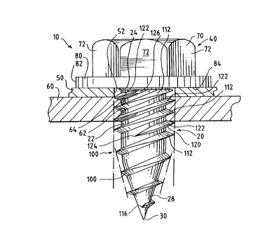
As shown in Figure 1, a fastener 10 of the type noted above constitutes a
first embodiment of this invention. Except as illustrated and described
herein, the
fastener 10 is similar to the fastener disclosed in U.S. Patent No. 5,779,417
(ITW Case
8048) the disclosure of which may be referred to for further details.
The fastener 10 has a shank 20, which defines an axis and which is threaded
in a unique manner and a head 40, which is unitary with the shank 20. The
shank 20
has a generally cylindrical portion 22, which has a proximal end 24 adjoining
the
head 40 and a distal end 26 and a tapered tip 28, which has a rounded end 30
and
which adjoins the shank 20 at the distal end 26.
As shown in Figure 1, the fastener 10 is employed for fastening a faying
plate 50, which is prepared, as by punching, with a clearance hole 52, to a
substrate
60, which is prepared, as by drilling, with a tapping hole 62. Before the
fastener 10 is
driven, the clearance hole 52 and the tapping hole 62 are circular, the
clearance hole
52 having a comparatively larger diameter and the tapping hole 62 having a
comparatively smaller diameter. When the fastener 10 is driven rotatably, the
shank
is adapted to pass freely through the clearance hole 52, to enter the tapping
hole
62 at the tapered tip 28 and to tap a complementary thread 64 around the
tapping
20 hole 62.
As shown, the head 40 has a driving portion 70 with a hexagonal
shape defining tool-engaging flats 72 whereby the driving portion 70 is
adapted to be rotatably driven by a pneumatically powered driving tool (not
shown)
of a conventional type having a driving head coacting with the tool-engaging
flats 72 so as to drive the fastener 10 rotatably about the axis
CA 02296883 2000-O1-24
-6-
defined by the shank 20. The head 40 has a bearing portion 80 adjoining the
shank 20, having an annular, peripheral edge 82, and having a clamping
surface 84 facing the tapered tip 28 of the shank 20. In other embodiments
(not shown) contemplated by this invention, the head of the fastener may
have a different shape, such as the truss or dome shape shown in Figure 1A.
Except as explained herein, the precise shape of the head is outside the scope
of this invention.
The shank 20 is formed so as to have a primary thread formation 100,
which is continuous, which is self tapping, and which defines axially spaced
threads 112 having a generally uniform radial dimension along the generally
cylindrical portion 22 of the shank 20 and similarly spaced threads 114 along
the tapered tip 28. The primary thread formation 100 originates at a region
116 near the pointed end 30 of the tapered tip 28 and tapers outwardly
toward the distal end 26 of the generally cylindrical portion 22 of the shank
20. The radial dimension of the primary thread formation 100 increases from
the region 116, along the tapered tip 28 to the distal end 26 of the generally
cylindrical portion 22, until the radial dimension thereof reaches the
generally uniform dimension thereof along the generally cylindrical portion
22.
The shank 20 is formed so as to have a secondary thread formation
120, which is continuous, which is self tapping, and which defines axially
spaced threads 122 between some of the threads 112 defined by the primary
thread formation 100, along the generally cylindrical portion 22 of the shank
20. The secondary thread formation 120 originates at a region 124 near the
distal end 26 of the generally cylindrical portion 22. The secondary thread
formation 120 has a radial dimension that tapers outwardly so as to increase
continuously over approximately three thread pitches, as shown, from the
region 124 to a region 126 on the generally cylindrical portion 22, at which
CA 02296883 2000-O1-24
_'
region 126 the radial dimension of the secondary thread formation 120
reaches a maximum radial dimension of the secondary thread formation 120.
Being uniform between the region 126 and the proximal end 24 of the
generally cylindrical portion 22 of the shank 20, the maximum radial
dimension of the secondary thread formation 120 is equal approximately to
the generally uniform radial dimension of the primary thread formation 100
along the generally cylindrical portion 22 of the shank 20.
The secondary thread formation 120, which is designed for a range of
plate thicknesses and substrate thicknesses, has an axial length that is
determined by the combined thickaesses of the faying plate 50 and the
substrate 60. With thicker plates and thicker substrates, a greater portion of
the axial length of the secondary thread formation 120 is engaged. With
thinner plates and thinner substrates, a lesser portion of the axial length of
the
secondary thread formation 120 is engaged. With thinner plates and thinner
substrates, however, the secondary thread formation 120 engages the
substrate 60 where the secondary thread formation 120 has tapered outwardly
so as to cut deeply into the substrate 60, whereby minimum stripping torque
tends to be much greater compared to what the stripping torque would have
been if the secondary thread formation 120 were omitted. Preferably, the
secondary thread formation 120 has an axial length enabling the fastener 10
to be effectively employed where the faying plate 50 has a thickness in a
range from approximately 0.010 inch to approximately 0.200 inch,
commonly from approximately 0.010 inch to approximately 0.035 inch, and
where the substrate 60 may have a greater thickness.
As represented graphically in Figure 2A for a typical fastener similar
to the fastener shown in Figure 1A, a wide range is found to exist between
the statistically maximum tapping torque and the statistically minimum
stripping torque for the respective fasteners when tested by being driven by
CA 02296883 2000-O1-24
_g_
similar pneumatically powered tools, at similar rotational speeds, through
similar workpieces (faying plates and substrates) prepared with similar
clearance and tapping holes. It is evident that stripping torque is maximized
while tapping torque is minimized.
As shown in Figure 1B, in a modified version, the secondary thread
formation 120 is interrupted so as to have a portion 130 nearer to the head 40
and a portion 140 nearer to the tip tapered 28 of the shank 20, for an axial
length equal to about one pitch. An interrupted portion 150 originates about
one pitch closer to the head 40, as measured axially from the region 124
where the secondary thread formation 120 originates, and extends axially
toward the head 40 for about one pitch.
As represented in Figure 2B, a typical fastener according to the
modified version shown in Figure 1B exhibits two peaks of tapping torque,
each lower than the peak of tapping torque exhibited by a typical fastener
according to an unmodified version, in which the secondary thread formation
100 is continuous, as shown in Figure 1A.
As shown in Figure 3, in which reference numbers with primes refer
to elements similar to elements referenced by similar numbers without primes
in Figure 1, a fastener 10' of the type noted above constitutes a second
embodiment of this invention. Except as illustrated and described, the
fastener 10' is similar to the fastener 10 and can be similarly used to fasten
a
faying plate 50' to a substrate 60'.
The fastener 10' has a shank 20', which is similar to the shank 20 of
the fastener 10, and a head 40', which is similar to the head 40 of the
fastener
10. The shank 20' defines an axis and has a generally cylindrical portion 22',
which has a proximal end 24' adjoining the head 40' and a distal end 26', and
a tapered tip 28'. The shank 20' has a primary thread formation 100', which
defines axially spaced threads 122' along the generally cylindrical portion
22'
CA 02296883 2000-O1-24
-9-
and which has a generally uniform radial dimension along the generally
cylindrical portion 22', is similar to the primary thread formation 100 of the
shank 20 of the fastener 10. The shank 20' has a secondary thread formation
220, which defines axially spaced threads 222 between some of the threads
122' defined by the primary thread formation 100', differs from the secondary
thread formation 120 of the shank 20 of the fastener 10.
The secondary thread formation 220 originates at a region 224 near
the distal end 26' of the generally cylindrical portion 22' of the shank 20'.
The secondary thread formation 220 has a radial dimension that tapers
outwardly so as to increase continuously, as shown, from the region 224 to a
region 226 on the generally cylindrical portion 22', at the proximal end 24',
at
which region 226 the radial dimension of the secondary thread formation 120
reaches a maximum radial dimension, which is less than the generally
uniform radial dimension of the primary thread formation 100' along the
generally cylindrical portion 22' of the shank 20'.
For a typical fastener similar to the fastener 10', a wide range is
predicted to exist between the tapping torque and the stripping torque for the
respective fasteners when tested by being driven by similar pneumatically
powered tools, at similar rotational speeds, through similar workpieces
(faying plates and substrates) prepared with similar clearance and tapping
holes.
Various modifications may be made in either embodiment described
above without departing from the scope and spirit of this invention.