Note: Descriptions are shown in the official language in which they were submitted.
CA 02296988 2000-O1-18
Drabeck 3-9-9-3-3-3-12
SYSTEM AND METHOD FOR CONTROLLING ANTENNA
DOWNTILT/UPTILT IN A WIRELESS COMMUNICATION
NETWORK
Field Of The Invention
The present invention relates to a wireless communication system and method
for
controlling antenna downtilt/uptilt.
Description Of Related Art
Conventional wireless communication systems include a plurality of cell sites,
each having a base station sending and receiving signals over one or more
associated
antennas or antenna modules. The antenna module usually includes at least' one
receive
and one transmit antenna, but could use a single antenna for both the transmit
and
receive functions. The radiation pattern (particularly, the main lobe) of, for
example, a
transmitting antenna at a cell site may be tilted from a horizontal reference
of the antenna
by a certain angle. This angle is referred to as the downtilt angle of the
antenna, and is
measured to be positive from the horizontal reference of the antenna towards
the ground.
Accordingly, an antenna with a downtilt angle of 10 degrees tilts towards the
ground
more than an antenna with a downtilt angle of 5 degrees.
I S Each antenna has a coverage area, which is a geographic area in which a
mobile
terminal will communicate with a base station associated with the antenna. The
extent of
an antenna's coverage area is affected by its downtilt angle and the downtilt
angles of
surrounding, but not necessarily adjacent, antennas.
Conventionally, the downtilt angles of the antennas in wireless communication
systems are set at the time of system installation according to predetermined
downtilt
angles. Installation workers climb up each antenna tower or support (e.g., a
building),
supporting antennas in the system, and manually fix the downtilt angle of each
antenna
according to the predetermined values. If the downtilt angle needs to be
changed after
the network installation, the worker has to once again climb up the antenna
tower to
CA 02296988 2000-O1-18
Drabeck 3-9-9-3-3-3-12 2
manually adjust the downtilt angle of the antenna. While it may be practical
to make
adjustments of the wireless communication system in this manner to small
portions of the
system, making adjustments is cumbersome, time consuming, costly and
potentially
dangerous since it requires a worker to go up the antenna tower and adjust the
downtilt
angle of the antenna. The difficulty, cost and complexity, however, increases
as the
number of antennas requiring downtilt angle changes increases. Also, it is
impractical to
make downtilt angle adjustments based on short term events, such as changes in
the time
of day (e.g., mobile terminal traffic in a coverage area for a business
complex will be
greater during business hours), and most long term events (e.g., a change in
seasons
wherein foliage affects signal-to-noise ratio).
Because the downtilt angles of antennas in a wireless communication system
directly effect the quality of system performance, a demand exists for a
simple, easy and
cost effective manner in which to change the downtilt angles of the antennas
in a wireless
communication system to improve system performance. Typically, operators
monitor
the quality of their system by taking operational measurements indicative
thereof. These
operational measurements include, but are not limited to, co-channel
interference (i.e.,
interference between two signals using the same channel frequency), signal-to-
noise plus
interference ratios within coverage areas, bit error rates within coverage
areas, call
blocking rates (e.g., the ratio of ( 1 ) the number of mobile terminals in a
coverage area
having their call requests denied by the base station because of insufficient
resources at
the base station which are dedicated to (2) the antenna module for that
coverage area to
the number of mobile terminals requesting calls in the coverage area) within
coverage
areas, etc. For example, signal strength interference measurements between two
coverage areas can indicate an amount by which signals transmitted by adjacent
antennas
overlap; and therefore, provide an indicator as to the quality of hand-offs
bemeen
coverage areas for these adjacent antennas. As another example, high call
block rates can
indicate unacceptable levels at which customers (i.e., mobile terminal users)
are denied
service and/or an overload condition. Typically, when the call blocking rate
or other
measure of load on a base station is greater than a predetermined threshold,
the base
station serving that coverage area or the coverage area itself is said to be
overloaded
CA 02296988 2000-O1-18
Drabeck 3-9-9-3-3-3-12 3
Some of the operational measurements are made by one or more test receivers at
known measurement locations within the wireless communication system, and
making
the operational measurements using the test receiver. Other operational
measurements,
such as call blocking rates, are made as part of system operation. The changes
in
operational measurements over time may reflect changes within the coverage
area such
as a population increase, addition of a new structure (e.g., a building), etc
that affect the
quality of system performance. Based on the operational measurements, changes
may be
made to the wireless communication system to improve the quality of system
performance.
For instance, when a problem, such as poor coverage (e.g., low signal-to-noise
ratio for signals received in a coverage area), is indicated by the
operational
measurements, the signal strength of signals transmitted by the antenna for
the problem
coverage area may be changed and the signal strength of signal transmitted by
one or
more antennas for coverage areas adjacent thereto may be changed until the
operational
measurements show acceptable coverage.
A demand, however, exists for greater freedom in addressing quality of system
performance concerns. Namely, a demand exists for improved, alternative or
additional
methods of addressing quality of system performance concerns. A simple, easy,
and cost
effective manner of adjusting the downtilt angles of antennas in a wireless
communication system would facilitate meeting such demands.
Summary Of The Invention
The present invention provides a wireless communication system including
antennas having electrically controllable downtilt angles and downtilt
controllers
associated with each antenna. The downtilt controllers receive instructions
from a main .
controller, and adjust the downtilt angles of the associated antennas in
accordance with
the received instructions. From the main controller, an operator can effect
changes that
vary from system wide changes in the downtilt angles of the antennas in the
system to
changes in the downtilt angle of a single antenna. From the base station
associated with
CA 02296988 2002-02-14
4
an antenna, an operator on the ground can effect changes in the downtilt angle
of the
associated antenna. Making changes in the downtilt angle, whether from the
base
station or the main controller, using the present invention avoids the costly
and
dangerous process of climbing a tower or other support structure to manually
adjust the
antenna's downtilt angle.
Because the process of changing downtilt angles is so simple with the present
invention, the present invention allows adaptive control of the downtilt
angles to
address issues of quality in the system, such as hand-off quality (e.g.,
signal overlap),
denial of service (e.g., load), co-channel interference, signal-to-noise plus
interference
ratios, bit error rate, etc, even during system performance. Furthermore, the
system
according to the present invention allows automating the process or portions
of the
process for addressing these quality issues.
In accordance with one aspect of the present invention there is provided a
wireless communication system, comprising: a plurality of cell sites, each
cell site
including an antenna having an electrically controllable downtilt angle and an
associated downtilt controller controlling a downtilt angle of said associated
antenna;
and a main controller outputting a control signal to at least two downtilt
controllers to
adjust said downtilt angle of said associated antennas and the relationship
therebetween.
In accordance with another aspect of the present invention there is provided a
method of controlling antenna tilt in a wireless communication system,
comprising:
providing a plurality of cell sites, each cell site including an antenna, each
antenna
having an electrically controllable downtilt angle and an associated downtilt
controller
controlling a downtilt angle of said associated antenna; outputting a control
signal to at
least two downtilt controllers to adjust said downtilt angle of said
associated antennas
such that the relationship between associated antennas is adjusted.
Brief Description Of The Drawings
The present invention will become more fully understood from the detailed
description given hereinbelow and the accompanying drawings which are given by
way
CA 02296988 2002-02-14
4a
of illustration only, wherein like reference numerals designate like parts in
the various
drawings, and wherein:
Fig. 1 shows a wireless communication system according to the present
invention;
Fig. 2 shows a diagram of a cell site in the system of Fig. l;
Fig. 3 shows a block diagram of a receiving antenna module used in the system
in Fig. 1; and
Fig. 4 shows a block diagram of a transmitting antenna module used in the
system in Fig. 1.
CA 02296988 2000-O1-18
Drabeck 3-9-9-3-3-3-12 5
Detailed Description Of The Preferred Embodiments
Initially the structure of the wireless communication system according to the
present invention will be described with respect to Figs. 1-4. Afterwards, the
operation
of the wireless communication system according to the present invention will
be
described in detail with reference to Figs. 1-4. An exemplary application of
the wireless
communication system according to the present invention will then follow.
WIRELESS COMMUNICATION SYSTEM
Fig. 1 illustrates a wireless communication system according to the present
invention. As shown, a plurality of cells Cell 1, Cell 2, ... each include a
cell site CS1,
CS2, ..., respectively. A mobile switching center (MSC) 200 communicates with
each
cell site CS l, CS2, . .. and a local exchange network 6. The local exchange
network 6
represents networks over which voice and/or data are communicated such as the
Public
Switched Telephone Network, the Integrated Service Digital Network, the
Internet,
other Internet protocol network, etc. The MSC 200 is any well-known MSC except
for
the addition of a main downtilt control unit (MDCU) 202. However, the MDCU 202
does not need to form part of the MSC 200, and instead, can be formed
separately and
even be located remotely from the MSC 200. The MDCU 202 is a data processing
system programmed to operate as described in detail below, and, which when
formed as
part of the MSC 200, utilizes the memory and user interfaces supplied by the
MSC 200.
When provided separately from the MSC 200, the MDCU 202 includes a user
interface,
memory, and an interface for interfacing with the MSC 200.
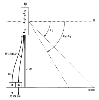
Fig. 2 shows an exemplary block diagram of each cell site CSI, CS2, . in the
wireless communication system according to the present invention. As shown
therein,
each cell site CS1, CS2,... includes at least one electrically controllable
antenna module
100, a support unit 102, a base station BS, and at least one downtilt
controller DC The
controllable antenna module l00 is mounted on the support unit 102. The base
station
BS communicates radio frequency (RF) signals to and from the antenna module
100, and
communicates with the MSC 200. The downtilt controller DC communicates w ith
the
CA 02296988 2000-O1-18
Drabeck 3-9-9-3-3-3-12 6
base station and the MSC 200 (more particularly, the MDCU 202), and controls
the
downtilt angle of the antenna module 100. The antenna module 100 includes one
or
more electrically controllable transmitting and/or receiving antennas. Such
controllable
antennas can be any type, such as an electrically controlled phased array
antennas,
motorized mechanically controlled phased array antennas, motorized
mechanically
downtiltable antennas, etc. These antennas can be configured as omni-
directional
antennas (azimuth angle of 360 degrees), three-sector antennas (azimuth angle
of 120
degrees), six-sector antennas (azimuth angle of 60 degrees), or any other
mufti-sector
antenna.
If a mufti-sector antenna system is used in each cell site CSI, CS2,..., each
cell
site CS1, CS2,...has an antenna module 100 and an associated downtilt
controller DC
corresponding to each sector. For example, each three-sector antenna system of
a cell
employs three antenna modules, each with its own coverage area, and three
downtilt
controllers DCs. A single base station BS still communicates RF signals to and
from the
antenna modules 100, but the resources of the base station BS are divided
among the
three antenna modules 100.
The support unit 102 can be an antenna tower or any other support unit known
in
the art for supporting the antenna module 100 above the ground. The base
station BS is
known in the art for transmitting, receiving, and monitoring wireless
communications,
e.g., mobile phone calls, paging messages, etc., through the antenna module
100
Fig. 3 shows a block diagram of a controllable receiving antenna module IOOa,
which may be used as the antenna module 100 in Fig. 2, according to the
present
invention. The antenna module I OOa is a voltage controllable phased array
antenna.
As shown in Fig. 3, the receiving antenna module 100a includes a plurality of
antenna elements 20,-20~, a plurality of filters 22,-22" connected to the
antenna elements
20,-20", a plurality of preamplifiers 24,-24" connected to the filters 22,-
22", a plurality of
phase shifters 26,-26" connected to the preamplifiers 24,-24", a combiner 28
connected
CA 02296988 2000-O1-18
Drabeck 3-9-9-3-3-3-12 7
to the phase shifters 261-26~, and a phase shift controller 29 connected to
the phase
shifters 261-26".
The antenna elements 201-20" receive RF signals from external sources, e.g., a
mobile terminal. The filters 221-22" filter the RF signals received by the
antenna elements
201-20" and the preamplifiers 24,-24" amplify the filtered RF signals. The
phases of the
RF signals output from the preamplifiers 24,-24~ are shifted by the phase
shifters 261-
26". The combiner 28 combines the outputs of the phase shifters 261-26" and
outputs the
combined signal to a receiver, e.g., the base station BS. The phase shift
controller 29
receives a control signal from the downtilt controller DC indicating the
desired downtilt
angle or desired change in the downtilt angle, and outputs corresponding
control signals
to control the phases of the phase shifters 261-26". Namely, in this phased
array antenna
module 100a, the downtilt angle of the antenna module 100a is changed by
varying the
phases of the phase shifters 261-26" to achieve the desired downtilt angle or
desired
change in the downtilt angle.
Fig. 4 shows an exemplary block diagram of a controllable transmitting antenna
module 100b, which may be used as the antenna module 100 in Fig. 2, according
to the
present invention. The antenna module IOOb is a voltage controllable phased
array
antenna.
As shown Fig. 4, the transmitting antenna module 100b includes a plurality of
antenna elements 30,-30", a plurality of filters 321-32~ connected to the
antenna elements
301-30", a plurality of power amplifiers 34,-34~ connected to the filters 32,-
s'_~, a
plurality of phase shifters 361-36" connected to the power amplifiers 341-34~,
a splitter 38
connected to the phase shifters 36,-36", and a phase shift controller 39
connected to the
phase shifters 361-36". Signals from a transmitter (e.g., the base station BS)
are split into
a plurality of transmitting signals by the splitter 38. The phase of each
transmitting signal
is shifted by a corresponding phase shifter 361-36", and amplified by a
corresponding
power amplifier 341-34". The filters 32,-32" filter the outputs of the power
amplifiers
341-34~, and the signals output from the filters 321-32" are transmitted by
the antenna
elements 301-30". The phase shift controller 39 receives a control signal from
the
CA 02296988 2000-O1-18
Drabeck 3-9-9-3-3-3-12 8
downtilt controller DC indicating the desired downtilt angle or desired change
in the
downtilt angle, and controls the phases of the phase shifters 361-36" based on
thereon.
Various modifications to both the receiving and transmitting antenna modules
100a and IOOb are possible. For instance, with respect to the transmitting
antenna
module 100b, the plurality of power amplifiers 361-36" could be replaced by a
single
power amplifier disposed before the splitter 38.
The transmitting and receiving antenna modules IOOa and 100b in Figs. 3 and 4
can be substituted or used in conjunction with any other type of antenna
module to form
the antenna module 100 in Fig. 2 according to the present invention.
Furthermore, the
transmitting and receiving antenna modules 100a and 100b may be integrated
into one
antenna module as known in the art, such that the antenna module 100 can be a
transmitting antenna module, a receiving antenna module, or a transmitting and
receiving
antenna module.
OPERATION OF THE WIRELESS COMMUNICATION SYSTEM
The operation of the wireless communication system according to the present
invention will now be described. When an operator at the MSC 200 enters a
desired
downtilt angle or desired change in the downtilt for an antenna module 100,
the MDCU
202 outputs a control signal to the downtilt controller DC for the antenna
module 100.
The control signal supplies the downtilt controller DC with the desired
downtilt ankle or
desired change in the downtilt angle. In response to the received control
signal, the
downtilt controller DC generates and outputs a control signal to the antenna
module 100
so that the desired downtilt angle or desired change in downtilt angle is
achieved by the
antenna module 100. In this manner, an operator located at MSC 200 can
remotely
control the downtilt angle of an antenna module 100.
However, the operation of the wireless communication system is not limited to
downtilt control originating from the MSC 200, controlling the downtilt of a
single
antenna module 100, or operator intervention in the downtilt control
operation.
CA 02296988 2000-O1-18
Drabeck 3-9-9-3-3-3-12 9
Instead of controlling the downtilt from the MSC 200, an operator at a base
station BS enters a desired downtilt angle or change in downtilt angle for an
antenna
module 100 associated with the base station BS. This information is supplied
by the base
station BS to the downtilt controller DC for the antenna module 100, and in
response to
this information, the downtilt controller DC generates and outputs a control
signal to the
antenna module 100 so that the desired downtilt angle or desired change in
downtilt
angle is achieved by the antenna module 100. Accordingly, downtilt control
from both
the MSC 200 and the base station BS eliminates the need to perform the costly
and
dangerous process of climbing the tower supporting the antenna module 100 in
order to
adjust the downtilt of the antenna module 100.
Instead of controlling the downtilt angle of a single antenna, an operator at
the
MSC 200 enters the desired downtilt angles or desired changes in downtilt
angles for as
many antenna modules 100 as desired. The MDCU 202 then outputs control signals
to
the downtilt controllers DCs for the antenna modules 100. Each control signal
received
by a downtilt controller DC indicates the desired downtilt angle or change in
downtilt
angle for the antenna module 100 associated therewith. Accordingly, the
downtilt
controllers DCs perform downtilt control of the antenna modules 100 in the
same
manner as discussed above. As a result, an operator at the MSC 200 can effect
substantially simultaneous changes in the downtilt angles of multiple antenna
modules
100. Therefore, making system wide changes to the downtilt angles of the
antennas
modules 100 in the wireless communication system according to the present
invention is
simple and easy.
The wireless communication system according to the present invention can be
used to simply and easily set the downtilt angles of the antenna modules I00
during
installation. However, the system according to the present invention also
simplifies
making changes to the downtilt angles of the antenna modules 100 as part of a
system
quality improvement effort to improve the call hand-off process, denial of
serv,~ice, etc.
As was described in the Background of the Invention section, operational
measurements,
such as co-channel interference, signal-to-noise plus interference ratios
within a coverage
area, bit error rates within a coverage area and signal strength measurements
between
CA 02296988 2000-O1-18
Drabeck 3-9-9-3-3-3-12 10
two coverage areas, indicative of .system quality are typically made using a
test receiver,
and improvements in these operational measurements are obtained through trial
and
error. According to the present invention, the downtilt angle of one or more
antenna
modules 100 may be changed and operational measurements taken after each
change
until the operational measurements indicate acceptable levels of quality.
Furthermore, the present invention allows these processes to become automated;
thus eliminating operator involvement. Namely, in one embodiment, the MDCU 202
is
programmed to make timed changes in the downtilt angles to compensate for time
dependent changes in load (e.g., change of seasons or commuting times). As a
result;
overload or unacceptable levels of service denial can be avoided. In another
embodiment,
the MDCU 202 receives operational measurements from the MSC 200, and is
programmed to determine the downtilt angles of antenna modules 100 according
any
known or future developed method for determining downtilt angles based on
operational
measurements such as call blocking rates. Using the determined downtilt
angles, the
MDCU 202 then outputs control signals to the appropriate downtilt controllers
DCs.
Accordingly, the wireless communication system according to this embodiment
permits
adaptive downtilt control based on even short term events. Next, an
application of this
embodiment of the wireless communication system will be described in detail.
APPLICATION OF WIRELESS COMMUNICATION SYSTEM TO AVOID
OVERLOAD IN AN AUTOMATED MANNER
As discussed previously, each antenna module 100 has a coverage area
dependent upon its downtilt angle. The larger the coverage area, the more
mobile
terminals that may be located within the coverage area requiring the limited
resources of
the base station BS dedicated to the coverage area of the antenna module 100
V'hen the
resources of the base station BS are exceeded by the demand for those
resources, the
base station BS and/or the coverage area is said to be overloaded. Numerous
criteria
exist for measuring the load on a base station BS or coverage area to judge
whether the
' base station BS and/or coverage area is overloaded. For the purposes of
discussion, the
remaining description will use the call blocking rate as the criterion for
measuring load,
CA 02296988 2000-O1-18
Drabeck 3-9-9-3-3-3-12 11
but the present invention in not limited to use of this criterion. The call
blocking rate may
also be defined in several ways, but again, for the purpose of discussion, the
call blocking
rate as used in this description is the ratio of ( 1 ) the number of mobile
terminals in a
coverage area having their call requests denied by the base station because of
insufficient
resources at the base station which are dedicated to the antenna module for
that
coverage area to (2) the number of mobile terminals requesting calls in the
coverage
area.
When the call blocking rate exceeds a first predetermined threshold value, the
base station BS is considered to be overloaded. The call blocking rate as the
measure of
load has been chosen because existing conventional MSCs measure the call
blocking
rates for each coverage area of the base stations associated therewith, and
supply the
MSC with the measured call blocking rates. Accordingly, how the call blocking
rates are
determined will not be described.
The present invention provides a simple and easy way to handle both long term
and short term events, such as load increases during peak commuting times. For
example, when a base station is in the overloaded state, the MDCU 202
determines
which coverage areas adjacent to the coverage area of the overloaded base
station are
available to handle the overload. For example, if the call blocking rate of a
base station
serving an adjacent coverage area is less than a second predetermined
threshold, which is
lower than the first predetermined threshold, the base station and adjacent
coverage area
are available.
The system according to the present invention then permits the MDCU 202 to
easily reduce the coverage area served by the overloaded base station by
increasing the
downtilt angle of the antenna module for that coverage area and/or increase
one or more
available coverage areas served by the available base stations by decreasing
the downtilt
angles of the antenna modules for the available coverage areas. This shifts
the boundary
between the coverage area of the overloaded base station and the coverage
areas
adjacent thereto to transfer load from the overloaded base station.
CA 02296988 2000-O1-18
Drabeck 3-9-9-3-3-3-12 12
While the adaptive and automated control application of the present invention
has
been described with respect to eliminating overload and thus reducing denial
of service,
the present invention also applies to improving other aspect of a wireless
communication
system such as the quality of hand-offs.
The wireless communication system according to the present invention is
applicable to any system such as a time-division multiple access system, a
code division
multiple access system, an analog system, etc.