Note: Descriptions are shown in the official language in which they were submitted.
CA 02297007 2003-02-24
APPARATUS FCaR CONTROL-~~ING HYBRID V~:HICLE
BACKGROUND OF' THE INVF;NTION
1. Field of the Invention
The invention relates to an apparatus for controlling
a hybrid vehicle havir-~d a:n internal combustion engine and a
motor (electr:~c motor) as driving sources for the vehicle.
2. Description of the~Rel.ated Bac)<:ground Art
A hybrid vehicle having an engine and a motor as
driving sources has co:'ZVentionally been well.:~nown. For
example, in one known control apparatus, the motor is
driven and an output o:E the engine i:~ control:led in
accordance with a driv:i.r~rcl state of tree vehicle.
Specifically, an operat=i.ng mode of the motor us
discriminated in aiccor::~anc~e with the dx wing state of the
vehicle, in an acceler..ri.irng made, a clriving electric power
is supplied to the mot~.w ~~nd the o~.ut~>ut of the engine is
assisted, and in a decc::>l.erating rnoc~e, the rnotc>r is set into
a regeneration braking state and a regeneration electric
power by the motor is c:v~ax-ged into a battery. The electric
power charged in t:he battery is used as a motor driving
electric power in the ~:n~celerating mode.
Even in the hybrica vehicle, an ai.r-fuel ratio of an
air-fuel mixture which is supplied to the engine is
controlled in <~ccordanc~e wit=h the driving state of the
vehicle. For instance, ~-~ahen the driving state indicates a
cruising driving, a target air-fuel ratica is set to a lean
CA 02297007 2000-O1-20
- 2 -
air-fuel ratio (for example, 16) for the purpose of
improvement of mileage and a lean burn control is
performed. In a driving state where an engine output is
needed, the target air-fuel ratio is set to a
stoichiometric air-fuel ratio (for example, 14.7) and a
stoichiometric burn control is performed. In the lean
burn control, since an output torque of the engine
decreases as compared with that in the stoichiometric burn
control, a difference of the output torque of the engine
is large at the time of driving in the case where the
control suddenly changes from the lean burn control to the
stoichiometric burn control or from the stoichiometric
burn control to the lean burn control. When this occurs,
a torque shock results.
It is well known that an electronic throttle valve
control apparatus to control an opening degree of a
throttle valve of an internal combustion engine is used to
reduce the torque shock. According to the electronic
throttle valve control apparatus, ordinarily, when a
driver operates an acceleration pedal, the opening degree
of the throttle valve is controlled so that the driver can
obtain a proper speed sense in correspondence to the
operation of the acceleration pedal. At the time of the
sudden change of the air-fuel ratio as mentioned above,
the electronic throttle valve control apparatus controls
the opening degree of the throttle valve irrespective of
the operation of the acceleration pedal and operates so
that the output torque of the engine does not suddenly
change. There is also a case where a secondary air
supplying apparatus for supplying secondary air into an
CA 02297007 2000-O1-20
- 3 -
intake pipe arranged on the downstream of the throttle
valve is used to similarly reduce the torque shock.
Even if the electronic throttle valve control
apparatus or secondary air supplying apparatus operates in
order to prevent the change in output torque of the engine
when the air-fuel ratio suddenly changes, however, there
is a problem that the output torque difference cannot be
sufficiently compensated so as not to cause a torque shock
because of a time delay which is caused until a control
result is reflected due to a delay of the air supply to
the engine.
SUMMARY OF THE INVENTION
It is, therefore, an object of the present invention
to provide a control apparatus of a hybrid vehicle which
can sufficiently compensate an output torque difference of
an engine at the time of sudden change of an air-fuel
ratio of a supply air-fuel mixture without a time delay.
According to the present invention, there is provided
a control apparatus of a hybrid vehicle having an internal
combustion engine and an electric motor as driving sources
for the vehicle, the electric motor operating as a motor
to assist an output of the internal combustion engine and
operating as a generator to regenerate running energy of
the vehicle and to charge voltage storage means. The
apparatus comprises: air-fuel ratio detecting means for
detecting a change in air-fuel ratio of an air-fuel
mixture which is supplied to the engine; and electric
motor control means for making the electric motor
operative as a motor when it is detected by the air-fuel
ratio detecting means that the air-fuel ratio has changed
CA 02297007 2000-O1-20
- 4 -
from a rich side value to a lean side value, and for
making the electric motor operative as a generator when it
is detected that the air-fuel ratio changed from the lean
side value to the rich side value.
According to the control apparatus of a hybrid
vehicle of the invention, for example, when it is detected
that the air-fuel ratio of the supply air-fuel mixture to
the engine changed to the lean side value because the
control is changed from the stoichiometric burn control to
the lean burn control, the electric motor is made
operative as a motor in order to assist the output of the
engine immediately after that, and for instance, when it
is detected that the air-fuel ratio of the supply air-fuel
mixture changed to the rich side value because the control
is changed from the lean burn control to the
stoichiometric burn control, the electric motor is made
operative as a generator for the purpose of regeneration
braking immediately after that. The output torque
difference of the engine, therefore, at the time of the
change in air-fuel ratio of the supply air-fuel mixture
can be sufficiently compensated without a time delay.
In the control apparatus of a hybrid vehicle of the
invention, the output torque difference of the internal
combustion engine when the change in the air-fuel ratio is
detected is presumed in accordance with the driving state
of the vehicle, and one of a driving force and a
regeneration braking force of the electric motor is
controlled in accordance with the presumed output torque
difference, so that a proper driving state or regenerating
state of the motor can be obtained for the output torque
CA 02297007 2000-O1-20
- 5 -
difference of the engine at the time of the change in air-
fuel ratio of the supply air-fuel mixture.
Further, in the control apparatus of a hybrid vehicle
of the invention, when it is detected by the air-fuel
ratio detecting means that the air-fuel ratio has changed
to the lean side value, the electric motor is made
operative as a motor and, after that, the driving force of
the motor is gradually decreased, and when it is detected
by the air-fuel ratio detecting means that the air-fuel
ratio has changed to the rich side value, the electric
motor is made operative as a generator and, after that,
the regeneration braking force of the generator is
gradually reduced, so that the force can be made coincide
with the proper output torque after the sudden change of
the air-fuel ratio without causing a torque shock.
BRIEF DESCRIPTION OF THE DRAWINGS
Fig. 1 is a block diagram showing an embodiment of
the invention;
Fig. 2 is a block diagram showing an internal
construction of an MOTECU in an apparatus in Fig. 1;
Fig. 3 is a flowchart showing a motor control
routine;
Fig. 4 is a flowchart showing a continuing portion of
the motor control routine of Fig. 3;
Fig. 5 is a diagram showing setting characteristics
of an acceleration flag FMAST according to an assist
trigger table;
Fig. 6 is a flowchart showing an accelerating mode
process;
Fig. 7 is a diagram showing an ASTPWR data map at the
CA 02297007 2000-O1-20
- 6 -
time of acceleration;
Fig. 8 is a flowchart showing a decelerating mode
process;
Fig. 9 is a diagram showing a first deceleration
REGEN data map;
Fig. 10 is a diagram showing a second deceleration
REGEN data map;
Fig. 11 is a flowchart showing a torque control
routine;
Fig. 12 is a flowchart showing a continuing portion
of the torque control routine of Fig. 11;
Fig. 13 is a diagram showing a stoichiometric torque
data map;
Fig. 14 is a diagram showing a relation between a
presumed torque difference and an assist amount or
regeneration amount; and
Fig. 15 is a diagram showing a change in output
torque assist amount at the time of a lean burn control
and a change in output torque reduction amount at the time
of a stoichiometric control.
DETAILED DESCRIPTION OF THE PREFERRED EMBODIMENT
An embodiment of the present invention will now be
described in detail hereinbelow with reference to the
drawings.
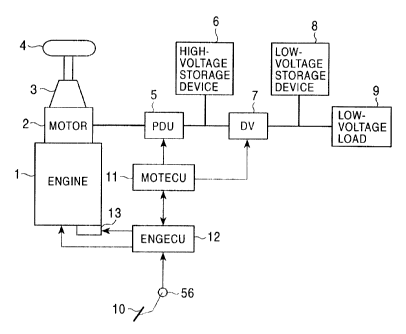
Fig. 1 shows a control apparatus of a hybrid vehicle
according to the present invention. In the control
apparatus of a hybrid vehicle, a crank shaft of an engine
1 is directly coupled to a rotary shaft of a DC motor 2 as
an electric motor. The rotation of the rotary shaft of
the motor 2 is transferred to a driving wheel 4 through a
CA 02297007 2000-O1-20
_ 7 _
transmission mechanism 3. The transmission mechanism 3 is
of the manual type. A PDU (power drive unit) 5 is
connected to the motor 2. The PDU 5 supplies a driving
electric power to the motor 2 in an assist operating mode
in which the motor 2 is driven and made operative as a
motor so as to assist an output of the engine 1. The PDU
5 supplies a regeneration electric power of the motor 2 to
a high voltage storage device 6 comprising, for example, a
capacitor in a regeneration operating mode in which the
driving electric power is not supplied but the motor 2 is
made operative as a generator.
A DV (down converter) 7 is connected to a connecting
line between the PDU 5 and high voltage storage device 6.
The DV 7 converts a high voltage on the connecting line to
a low voltage of approximately 12V. A storage device 8 as
a low voltage capacitor is connected to an output of the
DV 7 and a low voltage load 9 of the vehicle is also
connected.
The rotation of the motor 2 is controlled by an
MOTECU (motor electronic control unit) 11 through the PDU
5. As shown in Fig. 2, the MOTECU 11 has: a CPU 31; an
RAM 32; an ROM 33; a counter 34; an input interface (I/F)
circuit 35; an output interface (I/F) circuit 36; an
input/output interface circuit 37; and an A/D converter
38. The CPU 31, RAM 32, ROM 33, counter 34, input I/F
circuit 35, output I/F circuit 36, I/O I/F circuit 37, and
A/D converter 38 are connected in common to a bus.
The counter 34 is reset by a crank pulse generated
from a crank angle sensor 41 and counts the number of
clock pulses generated from a clock generator (not shown),
CA 02297007 2000-O1-20
_ g _
thereby generating a signal indicative of an engine
rotational speed Ne.
A starter switch 42 to detect a start of the engine
1, a clutch switch 43 to detect an ON/OFF state of a
clutch (not shown) in the transmission mechanism 3, a
neutral switch 44 to detect a neutral state of the
transmission mechanism 3, and a brake switch 45 to detect
the operation of a brake pedal are connected to the input
I/F circuit 35. The input I/F circuit 35 holds and
outputs data indicative of the ON/OFF state of each of the
switches 42 to 45.
The A/D converter 38 is provided to convert analog
signals from a plurality of sensors for detecting vehicle
driving parameters such as intake pipe inner pressure PB,
cooling water temperature TW, throttle valve opening degree
TH, vehicle speed VS, acceleration pedal opening degree AP,
and the like into digital signals. The intake pipe inner
pressure PB is detected by an intake pipe inner pressure
sensor 52 provided for an intake pipe 51 arranged on the
downstream of a throttle valve 50. The cooling water
temperature TW is detected by a cooling water temperature
sensor 53. The throttle valve opening degree TH is
detected by a throttle opening degree sensor 54. Further,
the vehicle speed VS is detected by a vehicle speed sensor
55. The acceleration pedal opening degree AP as an
operation opening degree of an acceleration pedal 10 is
detected by an acceleration pedal sensor 56. A voltage
across the high voltage storage device 6 is supplied to
the A/D converter 38. A voltage QCAP across the high
voltage storage device 6 is derived as a digital value
CA 02297007 2000-O1-20
_ g _
from an output of the A/D converter 38.
The output I/F circuit 36 sets the operation of the
PDU 5 in response to an assist amount instruction or a
regeneration amount instruction which is formed by the
operation of the CPU 31, which will be explained
hereinlater. The input/output I/F circuit 37 is a circuit
to communicate data with an ENGECU (engine electronic
control unit) 12. An assist electric power (driving
electric power) according to an assist amount ASTPWR
designated by the assist amount instruction is supplied
from the PDU 5 to the motor 2. The PDU 5 obtains a
regeneration electric power according to a regeneration
amount REGEN designated by the regeneration amount
instruction, from the motor 2 and supplies it to the high
voltage storage device 6 and DV 7.
The ENGECU 12 performs an engine control such as fuel
injection control, ignition timing control, or the like of
the engine 1. Although a connecting line is omitted in
Fig. 2, the crank angle sensor 41, switches 41 to 45, and
various sensors 52 to 56 are connected to the ENGECU 12
and an oxygen concentration sensor 61 is also connected.
The oxygen concentration sensor 61 is provided for an
exhaust pipe 62 and detects oxygen concentration OZ in
exhaust gas. The oxygen concentration sensor 61 is a
sensor of a binary output type for generating different
levels at air-fuel ratios on the rich side and lean side
while a stoichiometric air-fuel ratio is used as a
threshold value. Since an internal construction of the
ENGECU 12 is similar to that of the MOTECU 11, its
description is omitted here. In the ENGECU 12, a fuel
CA 02297007 2000-O1-20
- 10 -
injection control routine is processed by a CPU (not
shown) and a fuel injection time To"t is determined by
using the vehicle driving parameters and engine rotational
speed Ne. The fuel injection time To"t is calculated by
using, for example, the following calculating equation.
Tons = T1 " Koz " KwoT " KLS " KTw x KTA
+ TACC + TDEC
Where, T1 indicates a basic fuel injection time as an
air-fuel ratio reference control value which is determined
by searching a data map from an ROM in the ENGECU 12 in
accordance with the engine rotational speed Ne and intake
pipe inner pressure PH. Ko2 denotes an air-fuel ratio
correction coefficient which is calculated in an air-fuel
ratio feedback control. KwoT denotes a fuel increase
amount correction coefficient at the time of a high load
as in the case where the throttle valve is fully opened.
KLS denotes a lean fuel coefficient. K~,, indicates a
cooling water temperature correction coefficient which is
set in accordance with the cooling water temperature Tw.
KTA shows an intake air temperature correction coefficient
which is set in accordance with an intake air temperature
TA. TA~~ denotes an acceleration increase value which is
set in accordance with a degree of acceleration of the
engine rotational speed Ne. TDEC shows a deceleration
decrease value which is set in accordance with a degree of
deceleration of the engine rotational speed Ne. The
correction coefficients KwoT~ ILLS, KTw. and KTA, acceleration
increase value TACO, and deceleration decrease value TDEC are
determined by searching the data map in the ROM.
For deciding the fuel injection time To"t, there are
CA 02297007 2000-O1-20
- 11 -
at least a rich burn control, a lean burn control, and a
stoichiometric burn control. Whether the rich burn
control, lean burn control, and stoichiometric burn
control is executed is determined in accordance with the
driving state of the vehicle. At the time of the rich
burn control, a target air-fuel ratio is set to a value
(for example, 11) smaller than the stoichiometric air-fuel
ratio (for example, 14.7) and the air-fuel ratio
correction coefficient Ko2 and fuel increase amount
correction coefficient KWOT are determined so as to obtain
the target air-fuel ratio. At the time of the lean burn
control, the target air-fuel ratio is set to a value (for
example, 16) larger than the stoichiometric air-fuel ratio
(for example, 14.7) and the air-fuel ratio correction
coefficient Ko2 and lean fuel coefficient KLS are determined
so as to obtain the target air-fuel ratio. At the time of
the stoichiometric burn control, whether the air-fuel
ratio is richer or leaner than the stoichiometric air-fuel
ratio as a target air-fuel ratio is discriminated on the
basis of an output level of the oxygen concentration
sensor 61, and the air-fuel ratio correction coefficient
Ko2 is set in accordance with a result of the
discrimination. The air-fuel ratio correction coefficient
Ko2 set as mentioned above is used in the calculating
equation of the fuel injection time Tout and the fuel
injection time To"t is determined.
An injector 63 is driven only for the determined fuel
injection time Tot- The injector 63 is arranged near an
intake port of the intake pipe 51 of the internal
combustion engine and injects the fuel when it is driven.
CA 02297007 2000-O1-20
- 12 -
In the ENGECU 12, the ignition timing control routine is
processed by the CPU and a spark discharge of a spark plug
(not shown) of an ignition device 64 is performed in
accordance with the ignition timing control.
Further, since the throttle valve 50 is a so-called
drive-by-wire (DBW) type valve, a throttle actuator 13 to
open the throttle valve 50 is provided for the engine 1.
In the ENGECU 12, a throttle valve opening degree control
routine is processed by the CPU, and a target throttle
valve opening degree 6th is determined in accordance with
the vehicle driving parameters such as throttle valve
opening degree TH, vehicle speed VS, acceleration pedal
opening degree AP. The opening degree of the throttle
valve 50 is controlled through the throttle actuator 13 so
as to obtain the target throttle valve opening degree At,,.
The control operation for the motor 2 will now be
described mainly with respect to the operation of the CPU
31. The CPU 31 of the MOTECU 11 repetitively executes a
motor control routine, for example, at every 10 msec,
discriminates the operating mode at that time as shown
below, and sets the assist amount ASTPWR or regeneration
amount REGEN corresponding to the discriminated operating
mode.
In the motor control routine, as shown in Figs. 3 and
4, the CPU 31 first discriminates whether the starter
switch 42 is ON or not (step S1). When the starter switch
42 is ON in order to start the engine 1, whether the
engine rotational speed Ne is equal to or less than a stall
rotational speed NCR (for example, 50 r.p.m.) at which it
can be regarded that the engine is stopped or not is
CA 02297007 2000-O1-20
- 13 -
discriminated (step S2). When Ne <_ NCR, a starting mode to
start the engine 1 is executed as a motor operation (step
S3).
When it is decided in step S1 that the starter switch
42 is OFF, whether an engine stop command has been
generated or not is discriminated (step S4). The engine
stop command is generated as a set of an engine stop
command flag when it is determined that the vehicle is in
a driving state where the driving of the engine should be
stopped in the execution of an engine stop discriminating
routine. If the engine stop command is not generated,
step S2 follows and whether the engine rotational speed Ne
is equal to or less than the stall rotational speed NCR or
not is discriminated. When the engine stop command is
generated, the opening degree TH of the throttle valve 50
is obtained from the output of the A/D converter 38 and
whether the throttle valve opening degree TH of the
throttle valve 50 is equal to or larger than a
predetermined idling opening degree THIDLE (opening degree
of almost full closure) or not is discriminated (step S5).
If Ne > NCR in step S2, namely, when the engine 1 is
driving, step S5 is executed. When TH >_ THIDLE, an
acceleration flag FMAST is searched from an assist trigger
table (step S6).
The assist trigger table has previously been written
in the ROM 33 and, as shown in Fig. 5, the acceleration
flag FMAST is set in accordance with the engine rotational
speed Ne and throttle valve opening degree TH. That is,
threshold values MASTH and MASTL gradually increase in
accordance with an increase of engine rotational speed Ne.
CA 02297007 2000-O1-20
- 14 -
When the throttle valve opening degree TH increases from a
value that is equal to or less than the threshold value
MASTL, the FMAST = 0 until TH exceeds the threshold value
MASTH. When TH exceeds the threshold value MASTH, FMAST =
1 as a driving state where the speed should be
accelerated. On the contrary, when the throttle valve
opening degree TH decreases from a value that is equal to
or larger than the threshold value MASTH, FMAST = 1 until
TH is smaller than the threshold value MASTL. When TH is
smaller than the threshold value MASTL, FMAST = 0.
After executing step S6, whether the searched
acceleration flag FMAST is equal to "1" or not is
discriminated (step S7). When FMAST = 0, the operating
mode is set to a cruising mode (step S8). When FMAST = l,
the operating mode is set to an accelerating mode (step
S9).
When it is determined in step S5 that TH < THIDLE,
the throttle valve 50 is almost fully closed. Then,
whether the vehicle speed VS is equal to 0 km/h or not is
discriminated (step S10). When VS = 0 km/h, the vehicle is
stopped. Then, whether the engine stop command has been
generated or not is discriminated (step S11). This
process is similar to that in step S4. When the engine
stop command is generated, the operating mode is set to an
idling stop mode in order to stop the driving of the
engine 1 (step S12). When the engine stop command is not
generated, the operating mode is set to an idling mode in
order to continue the idling driving of the engine 1 (step
S13).
When VS $ 0 km/h in step 510, the vehicle is running.
CA 02297007 2000-O1-20
- 15 -
Then, whether the engine stop command has been generated
or not is discriminated (step S14). This process is
similar to that in step S4. When the engine stop command
is generated, the operating mode is set to a decelerating
mode in order to decelerate the driving of the engine 1
(step S15). When the engine stop command is not
generated, whether an idling driving of the engine 1 has
been requested or not is discriminated (step S16). The
idling driving request is generated as a set of idling
flag when it is determined that the engine 1 should be set
to the idling driving state in the execution of an engine
idling discriminating routine. When there is the idling
driving request of the engine 1, the operating mode is set
into the idling mode (step S13). When there is not the
idling driving request, the operating mode is set to the
decelerating mode (step S15).
In each of the operating mode processes in steps S8,
S9, 512, S13, and 515, the assist amount ASTPWR or
regeneration amount REGEN is set. For example, the assist
amount ASTPWR is set in an accelerating mode process,
which will be explained hereinlater. The regeneration
amount REGEN is set in a decelerating mode process. The
CPU 31 generates the set assist amount ASTPWR or
regeneration amount REGEN to the output I/F circuit 36
(step S17). The output I/F circuit 36 controls the
operation of the PDU 5 in accordance with the assist
amount ASTPWR or regeneration amount REGEN supplied from
the CPU 31. In the case of the assist amount ASTPWR, the
PDU 5 supplies an assist electric power according to the
assist amount ASTPWR to the motor 2. In the case of the
CA 02297007 2000-O1-20
- 16 -
regeneration amount REGEN, the motor 2 is in a
regeneration braking state and the PDU 5 obtains a
regeneration electric power according to the regeneration
amount REGEN from the motor 2 and supplies it to the high
voltage storage device 6 or DV 7.
In the accelerating mode process, the CPU 31 first
performs an RAM initializing operation (step S21) as shown
in Fig. 6. In the initializing operation, for example,
the value of the regeneration amount REGEN or the like
temporarily stored in the RAM 32 is set to "0". After the
initializing operation, the CPU 31 reads out the ON/OFF
state of the clutch switch 43 and discriminates whether
the clutch is in a power transmission state or not (step
S22). When the clutch switch 43 is ON, since the clutch
is in a power-off state, the assist amount ASTPWR is set
to "0" (step S23). The DV 7 is controlled so as to supply
the regeneration electric power from the motor 2 to the
low voltage load 9 (step S24).
When the clutch switch 43 is OFF, the clutch is in
the power transmission state. Then, the ON/OFF state of
the neutral switch 44 is read out and whether the
transmission mechanism 3 is in a neutral state or not is
discriminated (step S25). When the transmission mechanism
3 is in the neutral state because the neutral switch 44 is
ON, the processing routine advances to step S23 and the
assist amount ASTPWR is set to "0".
When the transmission mechanism 3 is in an in-gear
state since the neutral switch 44 is OFF, the voltage QCAP
across the high voltage storage device 6 is read out and
whether the voltage QCAP is larger than a lower limit
CA 02297007 2000-O1-20
- 17 -
threshold value QCAPLMTL or not is discriminated (step
S26). The lower limit threshold value QCAPLMTL can be set
to a valid voltage which can be assisted by the motor 2,
for example, approximately 70~ of a full charging voltage
of the storage device 6 and can be properly set by a
capacitance of the storage device 6. If QCAP _< QCAPLMTL,
step S23 follows and the assist amount ASTPWR is set to
"0". If QCAP > QCAPLMTL, the assist amount ASTPWR is
obtained by searching the map (step S27). As shown in
Fig. 7, the assist amount ASTPWR which is determined in
accordance with the engine rotational speed Ne and throttle
valve opening degree TH has previously been written in the
ROM 33 as an acceleration ASTPWR data map as shown by
ASTPWR#nll - ASTPWR#n2010. The assist amount ASTPWR
corresponding to the engine rotational speed Ne and
throttle valve opening degree TH at that time can be
searched from the acceleration ASTPWR data map. After
step S27 was executed, the CPU 31 controls the DV 7 so as
to supply the charged electric power in the high voltage
storage device 6 to the low voltage load 9 (step S28).
In the decelerating mode process, the CPU 31 first
performs an RAM initializing operation (step S31) as shown
in Fig. 8. In the initializing operation, for example,
the value of the assist amount ASTPWR or the like
temporarily stored in the RAM 32 is set to "0". After
completion of the initializing operation, the CPU 31 reads
the ON/OFF state of the clutch switch 43 and discriminates
whether the clutch is in a power transmission state or not
(step S32). When the clutch switch 43 is ON, the clutch
is in the power-off state. Then, the regeneration amount
CA 02297007 2000-O1-20
- 18 -
REGEN is set to "0" (step S33).
If the clutch switch 43 is OFF, the clutch is in the
power transmission state. Then, the ON/OFF state of the
neutral switch 44 is read out and whether the transmission
mechanism 3 is in the neutral state or not is
discriminated (step S34). When the transmission mechanism
3 is in the neutral state because the neutral switch 44 is
ON, step S33 follows and the regeneration amount REGEN is
set to "0".
When the transmission mechanism 3 is in the in-gear
state because the neutral switch 44 is OFF, the DV 7 is
controlled so as to supply the regeneration electric power
from the motor 2 to the low voltage load 9 (step S35).
The voltage QCAP across the high voltage storage device 6
is read and whether the voltage QCAP is larger than an
upper limit threshold value QCAPLMTH or not is
discriminated (step S36). The upper limit threshold value
QCAPLMTH can be set to a voltage which can be charged by
the regeneration, for example, approximately 90~ of the
full charging voltage of the storage device 6 and can be
properly set in accordance with the capacitance of the
storage device 6. If QCAP >_ QCAPLMTH, step S33 follows
and the regeneration amount REGEN is set to "0". If RCAP
< QCAPLMTH, the ON/OFF state of the brake switch 45 is
read out and whether the vehicle is in a braking state
where a brake pedal was operated or not is discriminated
(step S37). When the vehicle is in a non-braking state
because the brake switch 45 is OFF, the regeneration
amount REGEN is obtained from a first deceleration REGEN
data map by searching the map (step S38). When the
CA 02297007 2000-O1-20
- 19 -
vehicle is in the braking state because the brake switch
45 is ON, the regeneration amount REGEN is obtained from a
second deceleration REGEN data map by searching the map
(step S39). As shown in Fig. 9, the regeneration amount
REGEN in a non-braking period which is determined in
accordance with the engine rotational speed Ne and intake
pipe inner pressure PB has previously been written in the
ROM 33 as a first deceleration REGEN data map as shown by
REGEN#nll ~ REGEN#n2010. As shown in Fig. 10, the
regeneration amount REGEN in a braking period which is
determined in accordance with the engine rotational speed
Ne and intake pipe inner pressure PB has previously been
written in the ROM 33 as a second deceleration REGEN data
map as shown by REGENBR#nll - REGENBR#n2010. The
regeneration amount REGEN corresponding to the engine
rotational speed Ne and intake pipe inner pressure PB at
that time, therefore, can be searched from the first or
second deceleration REGEN data map. In the data maps in
Figs. 9 and 10, as the engine rotational speed Ne is
larger, and further, as the intake pipe inner pressure PB
is larger, the regeneration amount REGEN increases. The
regeneration amount REGEN in the second deceleration REGEN
data map in the brake ON state is larger than that in the
first deceleration REGEN data map in the brake OFF state.
The CPU 31 processes the torque control routine, for
example, at every 10 msec separately from the motor
control routine. In the torque control routine, as shown
in Figs. 11 and 12, whether a flag FLEAN which is
indicative of lean burn torque correction is equal to "1"
or not is first discriminated (step S41). When FLEAN = 0,
CA 02297007 2000-O1-20
- 20 -
whether a flag FST which is indicative of stoichiometric
burn torque correction is equal to "1" or not is
discriminated (step S42). When FST = 0, a torque
difference ~Trq between an output torque TrqST of the engine
1 at the time of the stoichiometric burn control and an
output torque TrQLean of the engine 1 at the time of the
lean burn control is presumed (step S43). As shown in
Fig. 13, the output torque TrqST at the time of the
stoichiometric burn control which is presumed in
accordance with the engine rotational speed Ne and intake
pipe inner pressure PH has been written in the ROM 33 as a
stoichiometric torque data map as shown by TrqST#nll
TrqST#n2010. Although not shown, the output torque TrqLean
at the time of the lean burn control which is presumed in
accordance with the engine rotational speed Ne and intake
pipe inner pressure PH has been written as a lean torque
data map as shown by TrqLean#nll ~ TrqLean#n2010. Further,
an output torque Tr9Rich at the time of the rich burn
control which is presumed in accordance with the engine
rotational speed Ne and intake pipe inner pressure PB has
been written as a rich torque data map as shown by
TrQRich#nll - TrqRich#n2010. As the engine rotational speed
Ne is larger and as the intake pipe inner pressure PB is
larger, the presumed torque in each torque data map
increases. As the air-fuel ratio increases from a lean
value to a rich value, the presumed torque increases. In
step S43, the output torques TrqST and TrqLean corresponding
to the engine rotational speed Ne and intake pipe inner
pressure PB at that time are searched from the
stoichiometric data map and the lean torque data map,
CA 02297007 2000-O1-20
- 21 -
respectively. A difference between the output torques
TrqST and TrQLean obtained as search results is calculated
as a presumed torque difference ~Trq.
After the process in step S43 was executed, the CPU
31 discriminates whether the previous burn control is the
rich burn control or the stoichiometric burn control (step
S44). Since an information signal showing to which of the
rich burn control, stoichiometric burn control, and lean
burn control does the present burn control corresponds can
be obtained from the ENGECU 12, the discrimination in step
S44 is made by checking the contents of the information
signal. For example, in the fuel injection control
routine, to which one of the rich burn control,
stoichiometric burn control, and lean burn control
corresponds can be known from the target air-fuel ratio,
so that the information signal can be supplied to the CPU
31 during the process of the fuel injection control
routine. If the previous burn control is the rich burn
control or the stoichiometric burn control, the CPU 31
discriminates whether the present burn control is the lean
burn control or not (step S45). When the previous burn
control is the rich burn control or the stoichiometric
burn control and the present burn control is also the rich
burn control or the stoichiometric burn control, the
current processing routine is finished.
When the previous burn control is the rich burn
control or the stoichiometric burn control and the present
burn control is the lean burn control, this means that the
air-fuel ratio is in a sudden changing state to the lean
side value, and the flag FLEAN which is indicative of lean
CA 02297007 2000-O1-20
- 22 -
burn torque correction is set so as to be equal to "1"
(step S46). The assist amount ASTPWR corresponding to the
presumed torque difference ~Trq is set (step S47). In the
relation between the presumed torque difference OTrq and
the assist amount ASTPWR, as shown in Fig. 14, as the
presumed torque difference ~Trq is larger, the assist
amount ASTPWR increases. Since the relation has
previously been written as a data map in the ROM 33, the
CPU 31 obtains the assist amount ASTPWR corresponding to
the presumed torque difference 4Trq by searching the data
map and generates the assist amount ASTPWR to the output
I/F circuit 36 (step S48).
When it is determined in step S41 that FLEAN = 1,
this means that the engine is in a state during the
correction of the output torque just after the change to
the lean burn control. Then, the assist amount ASTPWR is
reduced by a predetermined amount (step S49). Whether the
assist amount ASTPWR has reached "0" or not is
discriminated (step S50). If ASTPWR > 0, step S48
follows. If ASTPWR = 0, the flag FLEAN is reset so as to
be equal to "0" (step S51). The current processing
routine is finished.
The assist electric power according to the assist
amount ASTPWR set as mentioned above is supplied from the
PDU 5 to the motor 2. The motor 2 acts as a motor which
is driven so as to assist the decreased amount of the
output torque of the engine 1. Since the assist amount
ASTPWR gradually decreases, an output torque assist amount
of the engine 1 by the motor 2 also gradually decreases as
shown in Fig. 15. Although a decrease amount and a
CA 02297007 2000-O1-20
- 23 -
decreasing time of the assist amount ASTPWR can be
properly set, the decrease amount can be set to a constant
value.
If it is determined in the discrimination in step S44
that the previous burn control is neither the rich burn
control nor the stoichiometric burn control but the lean
burn control, the CPU 31 discriminates whether the present
burn control is the rich burn control or the
stoichiometric burn control (step S52). If the previous
burn control is the lean burn control and the present burn
control is also the lean burn control, the current
processing routine is finished.
When the previous burn control is the lean burn
control and the present burn control is the rich burn
control or the stoichiometric burn control, this means
that the air-fuel ratio is in a sudden changing state from
the lean side value to the rich side value. Then, the
flag FST which is indicative of stoichiometric burn torque
correction is set so as to be equal to "1" (step S53).
The regeneration amount REGEN corresponding to the
presumed torque difference ~Trq is set (step S54). A
relation between the presumed torque difference ~Trq and
the regeneration amount REGEN is similar to that between
the presumed torque difference OTrq and the assist amount
ASTPWR shown in Fig. 14, namely, as the presumed torque
difference OTrq is larger, the regeneration amount REGEN
increases. Since the relation has previously been written
as a data map in the ROM 33, the CPU 31 obtains the
regeneration amount REGEN corresponding to the presumed
torque difference OTrq by searching the data map and
CA 02297007 2000-O1-20
- 24 -
generates the regeneration amount REGEN to the output I/F
circuit 36 (step S55).
When it is determined in step S42 that FST = 1, this
means that the engine is in a state during the correction
of the output torque just after the change to the
stoichiometric burn control. Then, the regeneration
amount REGEN is reduced by a predetermined amount (step
S56). Whether the regeneration amount REGEN has reached
"0" or not is discriminated (step S57). If REGEN > 0,
step S55 follows. If REGEN = 0, the flag FST is reset so
as to be equal to "0" (step S58). The current processing
routine is finished.
The PDU 5 operates so as to obtain the regeneration
electric power according to the regeneration amount REGEN
set as mentioned above from the motor 2. The motor 2 acts
as a generator which performs the regenerating operation
so as to reduce the increased amount of the output torque
of the engine 1. Since the regeneration amount REGEN
gradually decreases, an output torque decrease amount of
the engine 1 by the motor 2 also gradually decreases as
shown in Fig. 15. Although a decrease amount and a
decreasing time of the regeneration amount REGEN can be
properly set, the decrease amount can be set to a constant
value.
In the fuel injection control routine, the control is
temporarily set to the rich burn control at the time of
the fuel increase upon acceleration of the internal
combustion engine 1, is set to the lean burn control in
the case of the cruising driving or a low load, and is
usually set to the stoichiometric burn control in the
CA 02297007 2000-O1-20
- 25 -
other cases. When the air-fuel ratio changes, therefore,
from the rich air-fuel ratio (state in which the fuel is
excessive as compared with the stoichiometric air-fuel
ratio) smaller than the stoichiometric air-fuel ratio to
the lean side value, a situation that the motor is
controlled in each of the motor and the generator occurs.
When the lean burn torque correction flag FLEAN or
the stoichiometric burn torque correction flag FST is set
so as to be equal to "1", the processes of the motor
control routine is stopped. Each of the initial values of
the lean burn torque correction flag FLEAN and the
stoichiometric burn torque correction flag FST is equal to
.Ø. .
The embodiment has been described above with respect
to the case where the invention is applied to the control
apparatus for selectively performing any of the lean burn
control in which the air-fuel ratio of the supply air-fuel
mixture is controlled to the lean air-fuel ratio, the
stoichiometric burn control in which it is controlled to
the stoichiometric air-fuel ratio, and the rich burn
control in which it is controlled to the rich air-fuel
ratio. The invention, however, can be applied to the case
where the air-fuel ratio suddenly and largely changes
merely to the lean side value or rich side value.
In the above embodiment, when the air-fuel ratio
changes from the air-fuel ratio which is richer than the
stoichiometric air-fuel ratio or changes from the
stoichiometric air-fuel ratio to the air-fuel ratio which
is leaner than the stoichiometric air-fuel ratio, the
motor 2 operates as a motor. When the air-fuel ratio
CA 02297007 2000-O1-20
- 26 -
changes from the air-fuel ratio which is leaner than the
stoichiometric air-fuel ratio to the air-fuel ratio which
is richer than the stoichiometric air-fuel ratio or the
stoichiometric air-fuel ratio, the motor 2 operates as a
generator. The invention, however, is not limited to the
above cases but the motor 2 can be made operative as a
motor when the air-fuel ratio merely changes in the lean
direction and can be made operative as a generator when
the air-fuel ratio merely changes in the rich direction.
For example, the motor 2 can be made operative as a motor
when the air-fuel ratio changes in the lean direction in a
region where the air-fuel ratio is richer than the
stoichiometric air-fuel ratio, or the motor 2 can be made
operative as a generator when the air-fuel ratio changes
further in the rich direction in a region where the air-
fuel ratio is richer than the stoichiometric air-fuel
ratio. Moreover, the motor 2 can be made operative as a
motor when the air-fuel ratio changes further in the lean
direction in a region where the air-fuel ratio is leaner
than the stoichiometric air-fuel ratio, or the motor 2 can
be made operative as a generator when the air-fuel ratio
changes in the rich direction in a region where the air-
fuel ratio is leaner than the stoichiometric air-fuel
ratio. When the air-fuel ratio changes in the lean
direction or the rich direction, if the motor 2 operates
as a motor, the driving force of the motor is gradually
decreased and, if the motor 2 operates as a generator, the
regeneration braking force of the generator is gradually
decreased.
In Figs. 7, 9, and 10 used in the embodiment, as the
CA 02297007 2000-O1-20
- 27 -
engine rotational speed and the intake air negative
pressure are larger, the assist amount and the
regeneration amount of the motor 2 increase.
Although the embodiment has been described above with
respect to the case where the transmission mechanism 3 of
the vehicle is of the manual type, the invention can be
similarly applied to the case where the transmission
mechanism 3 is of the automatic type (including the non-
stage transmission mechanism). In the automatic type
transmission mechanism, the assist amount or the
regeneration amount can be searched from the ASTPWR data
map in Fig. 7 and the REGEN data maps in Figs. 9 and 10 in
accordance with, for example, the engine rotational speed
Ne and vehicle speed V5. The presumed output torque can be
similarly searched from the stoichiometric torque data map
in Fig. 13 and a rich torque data map (not shown) and a
lean torque data map (not shown) in accordance with, the
engine rotational speed Ne and vehicle speed VS.
Further, although the MOTECU 11 for motor control and
the ENGECU 12 for engine control are individually provided
in the embodiment, both the motor and the engine can be
controlled by a single ECU.
As mentioned above, in the control apparatus of the
hybrid vehicle of the invention, for example, when it is
detected that the air-fuel ratio of the supply air-fuel
mixture to the engine changed to the lean side value
because the control had changed from the stoichiometric
burn control to the lean burn control, the electric motor
acts as a motor in order to assist the force of the engine
just after the detection and, when it is detected that the
CA 02297007 2000-O1-20
- 28 -
air-fuel ratio of the supply air-fuel mixture to the
engine changed to the rich side value because the control
had changed from the lean burn control to the
stoichiometric burn control, the electric motor acts as a
generator for the purpose of regeneration braking just
after the detection, so that the output torque difference
of the engine when the air-fuel ratio of the supply air-
fuel mixture changes can be sufficiently compensated
without a time delay.
In the control apparatus of the hybrid vehicle of the
invention, the output torque difference of the internal
combustion engine when the change in air-fuel ratio is
detected is presumed in accordance with the driving state
of the vehicle and the driving force or the regeneration
braking force of the electric motor is controlled in
accordance with the presumed output torque difference, so
that the proper driving state or regenerating state of the
motor can be obtained for the output torque difference of
the engine when the air-fuel ratio of the supply air-fuel
mixture changes.
Further, in the control apparatus of the hybrid
vehicle of the invention, when it is detected by the air-
fuel ratio detecting means that the air-fuel ratio changed
to the lean side value, the electric motor acts as a motor
and, thereafter, the driving force of the motor is
gradually reduced, and when it is detected by the air-fuel
ratio detecting means that the air-fuel ratio changed to
the rich side value, the electric motor acts as a
generator and, thereafter, the regeneration braking force
of the generator is gradually reduced, so that the output
CA 02297007 2000-O1-20
- 29 -
torque can be made coincident with the proper output
torque after the sudden change of the air-fuel ratio
without causing a torque shock.
The invention, therefore, is useful as a control
apparatus of the hybrid vehicle.