Note: Descriptions are shown in the official language in which they were submitted.
CA 02297250 2000-O1-21
WO 99105482 PCT/IB98101168
1
REDUCTION IN OVERALL SIZE, WEIGHT AND EXTENSION OF
DYNAMIC RANGE OF FLUID METERING SYSTEMS
Field of the Invention
This invention pertains to multiple phase metering system
for use in the oil and gas industry and, more particularly,
to multiple phase metering system using microwave
measurements to measure the oil, water and gas components
of a three phase flow stream.
Background of the Invention
Separators are designed to cause separation of liquids and
gas or oil, water and gas. For good separation, separator
size must be large enough to give fluid time to slow down
and separate. This large size presents great problems for
measurements in cost of materials, weight, and space. This
invention deliberately uses undersize separators in
combination with measurement tools which do not require
perfect separation for accurate readings. Many systems
have been developed for measuring the oil, water and gas
volume flow rates or fractions of three phase flow in
industrial applications in the oil and gas industry. One
successful such system has been that known as the STARCUT~
(registered trademark of Texaco Inc.) water cut monitor
system. This system when used with an (generally <5%)
incline separator, or with a vertical separator in series,
can substantially eliminate gas from the STARCUT system's
measurement of oil/water ratio and has proven to be very
accurate in field use. The STARCUT~ system used as just
described is shown in U.S. Patent 5,127,272 and U.S. Patent
5,234,012 and U.S. Patent 5,625,293 which are incorporated
herein by reference for all purposes. The STARCUT~ system
accuracy can be better than 0.1% in high water cut (100%)
and low water cut (0%) cases and the presence of up to 15%
and 20% gas in the flow line does not significantly affect
this accuracy. However, reduction in size of the system
and the extension of the accurate measurement dynamic range
CA 02297250 2000-O1-21
WO 99!05482 PCT/IB98/01168 -
2
of the system would be most desirable for higher gas cut
values, say above 20~.
The previously referenced U.S. Pater_ts substantially
separate most of the gas from the fluid f_ow line prior to
its entry into the STARCUT~ system. However , the use of the
incline separator or vertical separatoY in series to
condition fluid flows to remove most gas causes the size of
the system to be much larger than is economic. Also,
since the STARCUT' system can handle up to 15-20% gas flow,
it is not necessary to eliminate substant=ally all of the
gas flow while measuring the oil/wa~er ratio very
accurately, therefore the combination c= gas sensitive
STARCUT~ with a fluid conditioner allows she reduction in
size of the overall system.
Brief Description of the Invention
In a first aspect, this invention p=ovides a system
for measuring the oil/water/gas, ratios ~n a multiphase
fluid flow stream having greater than 204 gas flow phase
comprising:
a monitor system capable of accurate~y measuring the
oil, water and gas content of a three ~zase fluid flow
regime having up to 20% gas flow therein;
a fluid preconditioner for "mostly" preconditioning
said three phase fluid flow regime to con~ain 20% or less
gas flow after passage therethrough; and
means for passing said three phase fluid flow regime
having greater than 20% gas flow therein through said fluid
flow preconditioner and then sequential-ly through said
monitor to produce output oil/gas/water rGtios.
In a second aspect, this invention p=ovides a method
for measuring the oil/water/gas ratios -~n a multiphase
fluid flow stream having greater than 20% gas flow phase,
comprising the steps of:
flowing said multiphase fluid flow stream having
greater than 20~ gas flow phase sequentially into a
"mostly" flow preconditioning system which bypasses from
the main fluid flow stream a portion of the gas phase flow
CA 02297250 2000-O1-21
WO 99/05482 PCT/IB98I01168 -
3
to produce an output flow stream having 20% or less of gas
phase flow;
flowing said output stream through a monitor system
capable of accurately measuring the oil, water and gas
content of a three phase flow regime having up to a 20% gas
flow phase; and
measuring with said monitor system the oil/water/gas
ration of said output stream.
In the present invention the fluid input to the
STARCUT° monitor system is conditioned prior to its input by
subjecting it to a partial phase separation. For this
purpose a separator deliberately undersized based on
conventional criteria which produces an output fluid stream
of "mostly" liquid is placed in series with the STARCUTa
monitor and the mostly gas stream can be made more liquid
free by allowing more gas to be in the liquid stream.
Feedback control from the STARCUT° monitor system can be
used to control the portioning of gas and liquid in the
pre-conditioning separator, if desired, as a function of
the oil, water and gas fraction measurements made by the
STARCUT° monitor. The STARCUT° monitor system is used with
a special piping and orifice system which causes isokinetic
(same fluid velocity) sampling from the flow stream into
the side stream mounted STARCUT° monitor. This has been
found to enhance the accuracy of measurement of the system
over a wide range of flow rates. This STARCUT° can allow
gas carry under into the liquid stream up to its limits of
detection which is currently set at 70% gas.
While one embodiment of the system of the present
invention is illustrated herein using a "mostly"
liquid/mostly gas (a 2D) phase separator ahead of the
STARCUT° monitor to condition the fluid prior to its entry,
it will be understood that, if desired,a mostly 3D (i.e.
mostly o~.l, mostly water, and mostly gas) separator could
be used for this purpose. Such 3D "mostly" separators for
flow line use are available from many sources such as NATCO
Inc. of Houston, Texas or Daniel Industries (INFAB
CA 02297250 2000-O1-21
WO 99/05482 PCT/IB98/01168 -
4
Division) of Houston, Texas but must be deliberately sized
using conventional separator criteria for less than 1/10
the flow ranges for ultimate use.
The invention will be best understood by reference to
the following detailed description thereof when taken in
conjunction with the accompanying drawings.
Brief Description of the Drawings
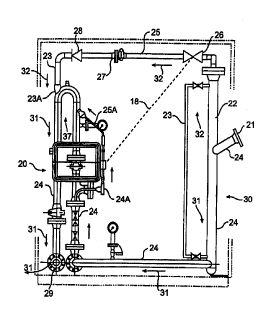
Figure 1 is a schematic drawing of a 2D deliberately
undersized conventional conditioner separator (mostly
liquid mostly gas) system used ahead of a STARCUT~ monitor
system to measure oil/water/gas ratio in a flowline.
Figure 2 is a schematic drawing of the STARCUT~
monitor system of Figure 1 showing its piping arrangement
used to obtain isokinetic sampling in the fluid flow line
being measured.
Description of the Preferred Embodiment
It has been experimentally determined through use of the
STARCUT~ monitor system in may flow regime environments that
the three phase measurement accuracy is enhanced if the
captured fluid velocity through the monitor system, which
is on a side flow line in parallel with the main flow
stream, is the same as that through the main flow line.
This principle is known as isokinetic sampling. Referring
initially to Figure 2 a schematic diagram of the STARCUT~
monitor side stream sampling from the main flow line which
achieves this is shown. Flow in the main line 11 is in the
direction of flow arrows 12. Flow into side stream
sampling line 13 is in the direction of flow arrows 15. It
will be understood that all references to fluid flow herein
refer to 3 phase mixed fluid flow of oil/water/gas.
Side stream flow line 13 directs the fluid flow
through a microwave test cell 16 which.comprises a part of
the STARCUT' monitor system shown generally as 20. The test
cell may be of the type described in more detail in U. S .
Patent No. 5, 625, 293 which is assigned to the assignee of
the present invention. The STARCUT~ monitor comprises a
microwave (10 GHz) energy source, microwave energy
CA 02297250 2000-O1-21
WO 99/05482 PCT/IB98101168
receivers, the test cell and means for redirecting flow
through the test cell. The operation of the system is
disclosed in more detail in the aforementioned U.S.
patents, but may be through of as measuring the phase shift
across the test cell, and the attenuation across the test
cell of the microwave energy. A computer portion 17 of the
STARCUT' monitor system takes these measurements and
interprets them in terms of the oil/water and gas ratio of
the fluid being measured. The computer portion 17 is also
capable of generating output control signals on a bus 18 to
other system components for their control as will be
described subsequently.
A first orifice 19 in the flow line 11 causes a
pressure drop via input line 13 and output line 14 across
the STARCUT' monitor which causes the input line 13 and
output line 14, each having a smaller diameter than the
main flow line 11, to have the same fluid velocity as that
in the flow line 11. Fluid is pulled through line 13 via
J;" and Jo~~ if desired. A flow straightener 11A is used to
restore flow consistency after making the several bends and
sidetracks for the measurement by the STARCUT~ monitor and,
finally, a second orifice 19A restores the original fluid
velocity prior to output.
Bearing in mind the foregoing, reference is now made
to Figure 1 which shows a preferred embodiment of the
measuring system accordingly to the present invention. A
piping system having a main flow line 24 is provided with
a 2D mostly liquid/mostly gas separator shown generally at
30. The separator 30 separates fluid in the input line 24
via input flange 21 into a primarily liquid component
flowing downwardly in flow line 24 and a primarily gas
component flowing upwardly in line 22. A level gauge 23
can be used to measure gas and liquid levels in the
separator 30.
The "mostly" liquid flow it will be understood is less
than 20~ gas in line 24 after passing through the separator
30. It is thus input via line 24A into the STARCUTa monitor
CA 02297250 2000-O1-21
WO 99/05482 PCTIIB98/01168 -
6
system 20 as shown. The STARCUT° monitor system operates as
previously described to determine oil/water and gas flow
rates and ratios in the flow line 24. The measured fluid
returns via line 25A to flow line 24 wherein the flow is in
the direction of flow arrows 31. Gas flow from separator
30 goes via a control valve 26 and line 25, through a wet
gas meter 27, check valve 29 into line 23 where it is
returned to main flow line 24 downstream of the STARCUT°
monitor system at 23A as shown in Figure 1. The rejoined
flow of gas and liquid at 23A goes in the direction of flow
arrows 31 and exits the system at flange 29.
The computer 17 part of STARCUT° monitor system 20
will be understood to be a dedicated digital processor of
considerable power based on such as an INTEL 40486
processor chip, several megabytes of Random Access Memory,
its own software operating system, etc. As such it is
capable of analyzing the oil/water/gas measurements of the
system and generating control signals on bus 18 to go to
globe valve 26 to control the flow of gas from the
separator 30. Closing valve 26 will drop the liquid level
in separator 30 and force more gas into the STARCUT° monitor
20. Opening valve 26 will allow the liquid level to rise
in the separator 30 and put less gas into the STARCUT°
monitor. By keeping the allowable gas flow into the
STARCUT° monitor within the 20~ tolerance for accurate
measurement, the fluid flow through the system can be
optimized and low liquid content has in the gas leg can be
also optimized.
As previously described a 3D ~~mostly~~ separator of the
types herein described could be used in place of the 2D
separator 30 of Figure 1, if desired. The forgoing
descriptions may make other equivalent changes and
modifications apparent to those of skill in the art. The
aim of the appended claims is to cover all such changes and
modifications that fall within the true spirit and scope of
the invention.