Note: Descriptions are shown in the official language in which they were submitted.
CA 02297316 2000-O1-27
1
H-203679
LAYERED ELECTRODE FOR ELECTROCHEMICAL CELLS
Field of the Invention
This invention relates to electrodes for use in
electrochemical cells.
to Background of the Invention
Electrochemical cells are desirable for various
applications, particularly when operated as fuel cells.
Fuel cells have been proposed for many applications
including electrical vehicular power plants to replace
internal combustion engines. One fuel cell design uses a
solid polymer electrolyte (SPE) membrane or proton
exchange membrane (PEM), to provide ion exchange between
the cathode and anode. Gaseous and liquid fuels are
2o useable within fuel cells. Examples include hydrogen and
methanol, and hydrogen is favored. Hydrogen is supplied
to the fuel cell's anode. Oxygen (as air) is the cell
oxidant and is supplied to the cell's cathode. The
electrodes are formed of porous conductive materials,
such as woven graphite, graphitized sheets, or carbon
paper to enable the fuel to disperse over the surface of
the membrane facing the fuel supply electrode. A typical
fuel cell is described in USPN 5,272,017 and USPN
5, 316, 871 (Swathirajan et al. ) .
Important aspects of a fuel cell include
reaction surfaces where electrochemical reactions take
place, catalysts which catalyze such reaction, ion
conductive media, and mass transport media. The cost of
power produced by a fuel cell is in part dependent on the
cost of the catalyst. The cost of power produced by a
CA 02297316 2000-O1-27
2
fuel cell is significantly greater than competitive power
generation alternatives, partly because of relatively
poor utilization of precious metal catalysts in
conventional electrodes. However, power produced from
hydrogen-based fuel cells is desirable because hydrogen
is environmentally acceptable and hydrogen fuel cells are
efficient. Therefore, it is desirable to improve the
catalyst utilization in fuel cell assemblies to render
fuel cells more attractive for power generation. It is
to also desirable to improve reactant gas diffusion and
movement of product water in the fuel cell.
CA 02297316 2003-07-02
3
Summary of the Invention
In one aspect there is provided an electrode structure
comprising:
(a) a current collector sheet, comprising a porous substrate
and a tetrafluoroethylene polymer;
(b) a barrier layer, comprising a proton conductive material
and carbon particles; and
(c) a catalyst layer, comprising a proton conductive material
and carbon particles;
wherein
(i) said barrier layer is between said current collector
sheet and said catalyst layer,
(ii) said barrier layer is uncatalyzed, or catalyzed with
catalytic particles,
(iii)said catalyst layer is catalyzed with catalytic
particles, and
(iv) the weight ratio of catalytic particles to carbon
particles of the barrier layer is less than 5:95, and
is less than the weight ratio of catalyst particles to
carbon particles of the catalyst layer.
In one embodiment, each one of the carbon particle
groups comprises a plurality of the carbon particles having
internal and external surfaces defining a plethora of pores
within and between the carbon particles. The very finely divided
catalytic particles are supported on the internal and the
external surfaces of the carbon particles.
In another embodiment, the first layer is uncatalyzed
and the second layer comprises the carbon particles having very
finely divided catalytic particles supported on the internal and
the external surfaces of the carbon particles.
Preferably, the first group of carbon particles is
characterized by a density of 0.1 grams per cubic centimeter or
less, corresponding to a volume per gram of at least 10 cubic
centimeters per gram. Desirably, the
CA 02297316 2000-O1-27
4
second group of carbon particles is characterized by a pH
which is in a range of about 6 to about 9. Preferably,
each one of the carbon particle groups is characterized
by a pH which is in a range of about 6 to about 9.
Desirably, the second group of carbon particles is
characterized by an average pore radius which is greater
than 5 nanometers. Each one of the layers further
comprises a proton conductive material intermingled with
the carbon particles and the catalytic particles.
Desirably, the catalytic particle loading of
the second layer is less than about 0.30 mg per cm2 of
electrode surface area. The catalytic loading of the
first layer is less than that of the second layer,
desirably is on the order of up to about 0.15 mg/cm2, and
preferably is on the order of up to about 0.02 mg/cm2.
In one aspect, the second layer comprises
catalytic particles and carbon particles in a weight
2o ratio of about 20:80. The proton conductive material
constitutes 30 to 35 percent by weight of said second
layer, and catalytic and carbon particles constitute the
balance.
In one embodiment there is provided a method of
making the improved electrode structure described above
for use in an electrochemical cell. The first layer of
the electrode is produced by forming a mixture comprising
proton-conductive material, a first group of carbon
3o particles, and optimally catalytic particles. The
mixture is applied to a current collector sheet to form a
film. The second layer of the electrode is produced by
forming a second layer over the first layer, where said
second layer comprises proton-conductive material, a
second group of carbon particles, and catalytic
particles. The amount by weight of catalytic particles
CA 02297316 2000-O1-27
relative to carbon particles of the second layer is
greater than that of the first layer. ' This method
produces an electrode having significantly increased
catalyst utilization, dramatic reduction of catalyst
5 loading, and which is consequently less expensive to
produce than electrodes produced by prior art methods.
There is also provided a method of making a
combination electrolyte and electrode structure for an
1o electrochemical cell having an electrolyte membrane of
solid polymer proton-conductive material and first and
second electrodes disposed on either side of the
electrolyte membrane. At least one of the electrodes is
formed by the method of the invention described above.
i5 The electrode produced in this method is then placed on a
first surface of the electrolyte membrane such that the
second layer faces the membrane. A second electrode is
placed on the opposite surface of the membrane and the
resulting structure is heated and compressed to adhere
2o the electrodes to the membrane. In a preferred
embodiment of the invention method the electrodes are
adhered to the membrane by subjecting the assembly to a
compressive load and an elevated temperature to result in
some of the particles becoming at least partially
25 embedded in the membrane, thereby providing a continuous
path for protons to the catalyst site where reaction
occurs.
The first and second groups of carbon particles
so are the same or different. That is, they may have the
same characteristics or differ in at least one
characteristic. In the case where both layers are
catalyzed, the catalyst of the respective layers may be
the same or different.
As can be seen from the description of the
CA 02297316 2000-O1-27
6
electrode, membrane electrode assembly, and the fuel cell
system described above, the invention provides improved
catalyst utilization and improved water management.
It is an object of the invention to provide new
electrodes and new membrane electrode assemblies.
Another object is to provide a method for preparing the
electrodes and assemblies containing the improved
electrodes. Advantageously, the membrane/electrode
to assembly of the invention provides relatively high power
output with unexpectedly low catalyst loading.
These and other objects, features and
advantages will become apparent from the following
description of the preferred embodiments, claims, and
accompanying drawings.
CA 02297316 2000-O1-27
7
Brief Description of the Drawings
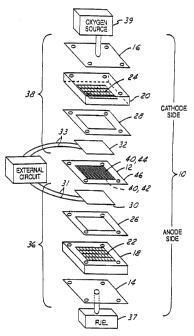
Figure 1 is a schematic view of an unassembled
electrochemical fuel cell having an electrode and a
combination membrane and electrode assembly according to
the invention.
Figure 2 is a pictorial illustration of a
cross-section of a membrane electrode assembly according
1o to the invention.
Figure 3 is a pictorial illustration of another
cross section of a membrane electrode assembly, and
having graphite sheets.
Figure 4 is a magnified illustration showing a
carbon particle supporting catalytic particles and
intermingled with proton conductive material.
2o Figure 5 shops the effect of the current
collector Teflon content on a PEM fuel cell operated at
80~C, Air/Hz, 3/1.2 Stoic, 30 psig. 20 w/o PtVu, 10 mil
SC, 0.5 g/cc, Nafion 112 membrane, Pt loading -
0.28mg/cmz/electrode.
Figure 6 shows the effect of using a primary
carbon/catalyst layer on PEM fuel cell performance 20 w/o
PtVu and 5 w/o Pt/AB were used for the main and primary
layers, respectively. Nafion 112 membrane; Pt loading:
0.35mg/cmz/electrode; Air/Hz, 80~C, 30 psig; 3/1.2
stoichiometry.
Figure 7 shows the effect of current collector
density on the PEM fuel cell performance operated at
80~C, Air/Hz. 3/1.4 Stoic and 30 psig. 20 w/o PtVu,
Nafion 112 membrane, Pt loading = 0.3mg/cmz/electrode.
CA 02297316 2000-O1-27
8
Figure 8 shows the effect of cathode Nafion
content on the PEM fuel cell performance when operated at
80~C, Air/H2, 3/1.5 Stoic 55/30 psig 20 w/o PtVu, 10 mil
SC 0.42 g/cc, 19 w/o Teflon, Dow membrane Pt loading -
0.45mg/cm2/Cell.
Figure 9 shows the volume of 1 gram of 10 w/o
carbon-supported Pt catalyst.
Figure 10 shows the effect of carbon type on
PEM fuel cell performance when operated at 0.5V, 80~C,
Air/H2, 30 psig, 3/1.5 Stoic 10 w/o Pt/Carbon, 10 mil SC,
0.42 g/cc, 25 w/o Teflon, Dow membrane,
Pt=0.11~0.02mg/cm2/electrode.
Figure 11 shows the effect of Vulcan XC-72R
treatment on PEM cell performance when operated at 80~C,
Air/HZ, 30 psig, 3/1.5 Stoic 10 w/o PtVu, 10 mil SC, 0.42
2o g/cc, 25 w/o Teflon, Dow membrane, Pt=0.23mg/cm2/Cell.
Figure 12 shows the effect of carbon type on
the platinum electrochemical surface area.
Figure 13 shows the plot of cell current
density at 0.5 Volts against the pH of the carbon slurry
used to disperse the Pt catalyst. Experimental
conditions same as Figure 10.
3o Figure 14 shows the plot of cell current
density at 0.5 Volts against the average pore radius of
the cathode carbon support. Experimental conditions same
as Figure 10.
CA 02297316 2000-O1-27
9
Detailed Description of the Preferred Embodiments
In one aspect there is provided an electrode
structure comprising a current collector sheet and first
and second layers of electrode material. Together, the
layers improve catalyst utilization and water management.
This layered arrangement is particularly useful as a
cathode. Before further describing the electrode
structure, the cell which includes the electrode will now
1o be described.
Referring to Figure l, an electrochemical cell
with a combination membrane electrolyte and electrode
assembly (MEA) 12 incorporated therein is shown in
pictorial unassembled form. Electrochemical cell 10 is
constructed as a fuel cell. However, the invention
described herein is applicable to electrochemical cells
generally. Electrochemical cell 10 comprises stainless
steel endplates 14, 16, graphite blocks 18, 20 with
openings 22, 24 to facilutate gas distribution, gaskets
26, 28, carbon sheet current collectors 30, 32 with
respective connections 31, 33 and the membrane
electrolyte and electrode assembly (MEA) 12. The two
sets of graphite blocks, gaskets, and current collectors
namely 18, 26, 30 and 20, 28, 32 are each referred to as
respective gas and current transport means 36, 38. Anode
connection 31 and cathode connection 33 are used to
interconnect with an external circuit which may include
other fuel cells.
Electrochemical fuel cell 10 operates with
gaseous reactants, one of which is a fuel supplied from
fuel source 37, and another is an oxidizer supplied from
source 39. The gases from sources 37, 39 diffuse through
respective gas and current transport means 36 and 38 to
opposite sides of the MEA 12.
CA 02297316 2000-O1-27
Figure 2 shows a schematic view of the assembly
12 according to the present invention. Referring to Fig.
2, porous electrodes 40 form anode 42 at the fuel side
5 and cathode 44 at the oxygen side. Anode 42 is
separated from cathode 44 by a solid polymer electrolytic
(SPE) membrane 46. SPE membrane 46 provides for ion
transport to facilitate reactions in the fuel cell 10.
In one arrangement, the electrodes of the invention
1o provide more effective proton transfer by close contact
between the electrode and the ionomer membrane to provide
essentially continuous polymeric contact for such proton
transfer. Preferably, the electrode is inset or at least
partially embedded in the membrane. Accordingly, the
MEA 12 of cell 10 has membrane 46 with spaced apart first
and second opposed surfaces 50, 52, a thickness or an
intermediate membrane region 53 between surfaces 50, 52.
Respective electrodes 40, namely anode 42 and cathode 44
are well adhered to membrane 46, at a corresponding one
of the surfaces 50, 52.
In one embodiment, respective electrodes 40
(anode 42, cathode 44) further comprise respective first
and second Teflonated (polytetrafluoroethylene coated,
impregnated) graphite sheets 80, 82, at respective sides
of membrane 46. (Figure 3) The anode active material is
disposed between the first surface 50 of the membrane and
the first sheet 80; the cathode active material is
disposed between the second surface 52 and the second
3o sheet 82.
SPE Membrane
The solid polymer electrolyte (SPE) membrane
46, of the present invention is well known in the art as
an ion conductive material. Such SPE membranes are also
CA 02297316 2000-O1-27
11
referred to as polymer electrolyte membranes (PEM).
Typical SPE membranes are described in U.S. Pat. Nos.
4,272,353, 3,134,697, and 5,211,984.
The SPE membranes or sheets are ion exchange
resin membranes. The resins include ionic groups in
their polymeric structured one ionic component of which
is fixed or retained by the polymeric matrix and at least
one other ionic component being a mobile replaceable ion
1o electrostatically associated with the fixed component.
The ability of the mobile ion to be replaced under
appropriate conditions with other ions imparts ion
exchange characteristics to these materials.
The ion exchange resins can be prepared by
polymerizing a mixture of ingredients, one of which
contains an ionic constituent. One broad class of cation
exchange, proton conductive resins is the so-called
sulfonic acid cation exchange resin. In the sulfonic
2o acid membranes, the catio~ ion exchange groups are
hydrated sulfonic acid radicals which are attached to the
polymer backbone by sulfonation.
The formation of these ion exchange resins into
membranes or sheets is also well known in the art. The
preferred type is perfluorinated sulfonic acid polymer
electrolyte in which the entire membrane structure has
ion exchange characteristics. These membranes are
commercially available, and a typical example of a
3o commercial sulfonated perfluorocarbon, proton conductive
membrane is sold by E.I. Dupont de Nemours & Co., under
the trade designation Nafion~. Another was developed by
Dow Chemical. Such proton conductive membranes may be
characterized by monomers of the structures
CFZ=CFOCFZCFZS03H, CFz=CFOCFZCF (CF3) OCF2SOsH, and -
CFzCF2CF (ORX) CFZCFZ-, where x is S03H or COZH. Nafion~ is
CA 02297316 2003-07-02
12
a fluoropolymer, and more specifically, a copolymer which
comprises perfluorinated carboxylic or sulfonic acid
monomeric units. Nafion~ polymers and polymer membranes
are Nafion~ polymers prepared from copolymers of
tetrafluoroethylene and perfluorinated monomers
containing sulfonic or carboxylic acid groups. The
perfluorinated sulfonic copolymer is preferred for the
invention.
1o In the electrochemical fuel cell 10 exemplified
by the invention, the membrane 46 is a cation permeable,
proton conductive membrane, having H+ ions as the mobile
ion; the fuel gas is hydrogen (or reformate) and the
oxidant is oxygen or air. The overall cell reaction is
the oxidation of hydrogen to water and the respective
reactions at the anode 42 and cathode 44, are Hz = 2H+ +
2 a ( anode ) and ~ Oz + 2H+ + 2 a = H 20 ( cathode ) .
Since hydrogen is used as the fuel gas, the
2o product of the overall cell reaction is water.
Typically, the product water is rejected at the cathode
44 which is the electrode 40 on the oxygen side.
Typically, water then escapes by simple flow or by
evaporation. However, means may be provided if desired,
for collecting the water as it is formed and carrying it
away from the cell. Water management in the cell is
important to the successful long-term operation of the
electrochemical fuel cell. Water management techniques
and cell designs related thereto are described in U.S.
3o Patent Nos . 5, 272, 017 (' 017 ) and 5, 316, 871 (' 871 ) . The
present invention further improves water management
during fuel cell operation, and is also directed to
other features such as effective electrode utilization,
effective proton transfer between electrodes and the
membrane, and good gas diffusion. These features are at
CA 02297316 2003-07-02
13
least partially enhanced by the improved electrode design
of the invention.
Electrodes
The electrodes of the invention comprise a
current collector and electrode active material which
engages in cell reactions. Electrochemical reactions in
a fuel cell occur in an interface region among the proton
1o conductive ionomer, catalyst, electron-conducting carbon,
and the gaseous reactant. Thus, for good catalyst
utilization, the electrode should be designed so that the
catalyst sites are in intimate contact with the proton
exchange membrane, the gaseous reactant, and the
electron-conducting carbon.
A conventional electrode may be made by methods
as described in U.S. Patent Nos. 5,272,017 and 5,316,871.
This is
2o exemplified by the anodev of Figures 2 and 3. In such
configuration catalyzed carbon particles are prepared and
then combined with the proton conductive binder in
solution with a casting solvent. The solution is applied
to a Teflonated graphite sheet 80, the casting solvent is
evaporated and the remaining layer comprising catalyzed
carbon particles and binder is then brought into contact
with, and hot-pressed to, the membrane. Here the
catalyzed carbon particles 60 are in intimate contact
with and adhered to the membrane 46. As described
3o herein, preferably some portion of the catalyzed carbon
particles are at least partially embedded in membrane 46.
Figure 4 is a pictorial illustration showing the
magnified view of a catalyzed carbon particle 60 with
very finely divided catalytic particles 62 carried
thereon. A proton conductive material 64 is intermingled
with particles.
CA 02297316 2000-O1-27
14
The new electrode configuration of the
invention is described herein for use as a cathode, but
is not limited thereby. It is thought to be useable for
either an anode or a cathode, and is here demonstrated to
be particularly advantageous when used as a cathode. The
electrode of the invention comprises a current collector
sheet 82, a first electrode layer 70, and a second
electrode layer 72. The first electrode layer 70 is
1o between the current collector sheet 82 and the second
layer 72. The first electrode layer comprises a first
group of carbon particles 60 and the second layer
comprises a second group of carbon particles 60. The
carbon particles of the first and second group may be the
same type of carbon particles and have the same physical
characteristics as shown in the tables. In another
embodiment, the carbon particles of the first and second
group are different types of carbon particles and have
different characteristics. Characteristics are as
2o defined in Table 2.
In one embodiment, the carbon particles of the
first group are uncatalyzed (Figure 3). In another
embodiment, the carbon particles of the first group
forming the first layer are catalyzed (Figure 2). The
catalyst 62 is in the form of very finely divided
catalytic particles, and typically are metallic particles
as further described below. In both embodiments, the
second layer 72 is catalyzed with finely divided
3o catalytic particles 62. The relative content of
catalytic 62 and carbon particles 60 of the first and
second layers is selected so that the weight ratio of
catalytic particles to carbon particles of the first
layer 70 is less than that of the second layer 72. It is
evident that where the first layer does not contain any
catalyst particles and the second layer is catalyzed,
CA 02297316 2000-O1-27
this condition will be met. In the embodiment where
catalytic particles are included in both layers, the
weight ratio of catalytic particles to carbon particles
in the second layer is greater than that of the first.
s
In one embodiment, the carbon particles of the
first layer comprise a plurality of internal and external
surfaces defining a plethora of pores; and the very
finely divided catalytic particles are supported on the
1o internal and external surfaces of the carbon particles
(Figure 4). Preferably the carbon particles 60 are
catalyzed with the catalytic particles 62 before being
mixed with a proton conductive material 64 to form the
first layer.
In one embodiment, the second layer is formed
in essentially the same way as the first layer. That is,
carbon particles are catalyzed with the catalytic
particles and then the catalyzed carbon particles are
2o mixed with the proton coi2ductive material. This mixture
is then applied to the first layer in order to form the
second layer.
The catalytic particles are preferably
metallic, metals or alloys. Most preferred are noble
metal catalysts such as platinum (Pt) and palladium (Pd).
In addition, other relatively stable metals can be used,
including for alloying. Examples are titanium,
ruthenium, rhodium, tungsten, tin or molybdenum.
The invention provides a method for forming the
multilayered electrode, having at least first and second
layers. The first layer is also referred to as primary
layer and the second layer being the main layer. The
s5 method of making an electrode structure comprises the
steps of (a) providing a current collector sheet 82; (b)
CA 02297316 2000-O1-27
16
forming a first layer 70 on the sheet which comprises
proton conductive material 64, a first group of carbon
particles 60, and optionally catalytic particles 62; and
(c) forming a second layer 72 over the first layer, where
the second layer comprises proton conductive material 64,
a second group of carbon particles 60, and catalytic
particles 62. The amount by weight of catalytic
particles relative to carbon particles of the second
layer is greater than that of the first layer. In one
to embodiment as per the aforesaid method, step (a) is
conducted by forming a first mixture of proton conductive
material, a first group of carbon particles, and a first
group of finely divided catalytic particles supported on
and in the carbon particles; and applying the first
mixture onto the surface of the current collector and
forming a first film from the mixture.
In one embodiment, step (c) is conducted by
forming a second mixture of proton conductive material, a
2o second group of carbon particles and a second group of
finely divided catalytic particles supported on and in
the carbon particles; and applying the second mixture
onto the first layer.
The membrane electrode assembly is prepared by
applying the multi-layer electrode and a counter-
electrode to a respective surface of the membrane and
then hot-pressing at a temperature and compressive load
sufficient to adhere the electrodes to the membrane.
3o Preferably at least a portion of the particles of the
electrodes are at least partially embedded in the
membrane which becomes softened during the high
temperature hot-pressing.
~ More specifically, the active material of the
anode 42 is applied to Teflonated graphite sheet 80.
CA 02297316 2000-O1-27
17
Then, the anode active material side carried on sheet 80
is contacted with the first surface 50 of the membrane
46. The multi-layer active material of the cathode 44 on
sheet 82 is contacted with second surface 52 of the
membrane 46. The applied sheets 80, 82 are hot-pressed
to the membrane while being heated for a time and at a
temperature and compressive load sufficient to soften the
membrane 46 and at least partially embed at least a
portion of the particles in the membrane to thereby form
1o the first and second electrodes 42, 44. The embedded or
inset particles are at least partially set in respective
surfaces of the membrane although they may not be totally
encompassed by the membrane or disposed below its
surface.
The step of heating while pressing is conducted
at about 250 to about 1000 pounds per square inch
compressive load for about one to about five minutes, and
at a temperature of about 280~F (130~C) to about 320~F
(160~C). It has been found that a compressive load of
about 500 pounds per square inch for about 1 to about 2
minutes at a temperature of about 300~F (about 150~C) is
effective. The compressive load may vary with time.
That is, less load and longer times may be used and the
converse also applies.
The embedding of electrodes into the membrane
under pressure, provides for a continuous path of proton
conductive material from one side of the membrane
3o electrode assembly to the other. The intimate
intermingling of proton conductive material with catalyst
and carbon particles provides a continuous path for
protons to the catalyst site where reaction occurs. The
method also achieves a relative optimum utilization of
catalytic particles, including adjacent the membrane at
the electrode.
CA 02297316 2000-O1-27
18
The proton conductive material and the
catalytic and carbon particles, forming the anode and the
cathode main (second) layer, are in a weight proportion
based on 100 parts, of about 30 to about 70 parts proton
conductive material and the balance being catalytic and
carbon particles. And, the catalytic and carbon
particles are in a proportion based on 100 parts by
weight of up to about 20 parts catalytic particles and
to the balance being carbon particles. The cathode primary
(first layer) is uncatalyzed or contains a lesser
proportion of catalytic particles. The amount is on the
order of 0.02 mg/cm2 catalytic particles. This
corresponds to about 5 parts by weight catalytic
particles and 95 parts by weight carbon particles.
In one embodiment the cathode comprises a first
layer which contains carbon particles intermingled with
proton conductive material; alternatively, the first
layer contains carbon particles catalyzed with a low
amount of platinum on the order of 0.02 mg/cm2 (5 weight
percent platinum) and the balance carbon. This layer
generally contains 40 weight percent proton conductive
material (Nafion) and the balance, the carbon or
catalyzed carbon, on the order of 60 weight percent.
This layer typically has a thickness of about 10 to about
13 microns. The second layer contains carbon particles
catalyzed with 20 weight percent platinum. The weight
proportion of Nafion to catalyzed carbon in the main
layer is in a range of 30 to 35 weight percent Nafion
(proton conductive material) and 65 to 70 weight percent
catalyzed carbon. It is desirable that the carbon
exhibit a pH in a slurry constituting the carbon and
water of about 6 to 9 pH. Preferably, the pH is greater
than 6.5, and is about 6.5 to about 9. It is preferred
that the average pore size be equivalent to a radius of
CA 02297316 2000-O1-27
19
greater than 5 nanometers. This represents the average
pore size of both mesopores and micropores. It is
preferred that the current collector, supporting the
primary (first layer) and main (second layer), has a
density on the order of 0.3 - 0.35 gm/cm2.
Example
In this example, a membrane electrode assembly
to (MEA) 12 was made. The anode was made by conventional
means and the cathode electrode was made by the improved
method of the invention. In both cases carbon paper was
used for the current collector and supported the active
material components of the electrode. In this example
both Nafion~ and Teflon~ are used. Nafion~ membrane and
Nafion~ solution were obtained from DuPont and Solution
Technology, respectively. Nafion~ is a registered
trademark of DuPont. Teflon~ is also a trademark of
DuPont.
Carbon Sheet Treatment
SpectraCarb (SC) Carbon sheets for the current
collector were obtained from Spectra Corp. Lawrence, MA,
in the thickness range 8 - 11 mils and density varying
from 0.26 g/cc to 0.7 g/cc. Carbon paper was coated with
Teflon by placing it horizontally on a rack and then
dipping the paper and rack in a well-stirred Teflon/water
mixture for 2 minutes. Teflon suspension was prepared by
3o mixing 1 part of Teflon 30 B solution from DuPont with 24
parts of de-ionized water by volume. After drying the
sheet at 120~C for 15 - 20 minutes, the paper was
sintered at 320~C for 15 minutes and 380~C for 30 - 60
minutes in a muffle oven. The Teflon content of the
sheet was calculated by weighing the sheet before and
after the Teflon treatment. The distribution of Teflon
CA 02297316 2003-07-02
in the carbon sheet was measured using electron
microprobe analysis. It was observed that the top
portion of the sheet had a higher Teflon content than the
bottom side.
s
MEA Preparation
After coating the carbon sheet with Teflon, the
side with the higher Teflon content was chosen for
1o coating a dual layered electrode structure. The primary
layer consisted of a barrier layer to prevent the
penetration of the catalyst slurry into the carbon sheet.
The slurry for the primary carbon/barrier layer was
prepared by mixing 1 g acetylene black (AB) with 5 w/o
15 Pt, 10 g de-ionized water and 13.4 g Nafion solution (5~
solution, Solution Technology) in an ultrasonic bath for
2 - 3 minutes to form a thick slurry. After applying a
layer of the AB slurry on the top side of a Teflonated
carbon sheet using a brush, doctor blade, or spray gun,
2o the sheet was dried under a heat lamp for 15 minutes at
100~C. The dry film had a catalyst loading of 0.02
mg/cm2, Nafion loading of 40 w/o and carbon black loading
of 60 w/o. TEM studies revealed the thickness of the
primary layer to be 10 - 13 Vim.
To support the cathode catalyst in the main
catalyst layer (second layer), nine carbon supports with
different properties were evaluated. The anode catalyst
support was Vulcan XC-72R prepared by conventional means.
3o Carbons used for the cathode catalyst were used both in
the as-received and heat treated forms. Heat treatment
was done at 1000~C for 1 hour in argon. The carbons were
catalyzed with a platinum (Pt) catalyst. The catalyst
was prepared by adding an aqueous solution of
hexachloroplatinic acid (Johnson Matthey) to a
carbon/water mixture followed by agitation for 1 hour.
* Trademark
CA 02297316 2000-O1-27
21
Pt (IV) was then reduced to the metallic state by the
addition of an excess of sodium borohydride that was
added drop-wise to the carbon slurry. After stirring the
mixture for another hour, the solution pH was adjusted to
ca. 7.0 by adding 1M sulfuric acid. Finally, the
platinum loaded carbon mixture was filtered, washed
thoroughly with water and dried in air at 100~C
overnight. A slurry was then prepared by thoroughly
mixing the platinized carbon with 5 w/o Nafion solution
(Solution Technology, Inc., Mendenhall, Pennsylvania):
The catalyst slurry was applied to the carbon sheet,
which had already been coated with the primary layer
(first layer). The catalyst slurry was applied by
brushing, and the electrodes were dried at 100~C for 1
is hour. The Pt loadings were calculated by weighing the
thoroughly dried carbon sheets before and after
application of each layer. To prepare the MEA, a Dow
experimental membrane or a Nafion 112 membrane was
sandwiched between the two electrodes and the MEA hot
2o pressed at 500 - 1000 lb./in2 for 1.5 - 2.0 minutes at
300~F.
MEA Evaluation
25 The membrane electrode assembly with a 25 cmZ
active electrode area was positioned in the single cell
test fixture (Electrochem, Inc.) made of graphite. The
single cell was operated by a Globe-Tech fuel cell test
station that controlled the cell potential or current,
3o temperature, pressure, mass flow of gases, and
humidification of reactant gases using an IBM PC-based
data acquisition and control system. To condition the
MEA, the cell was operated for 24 hours at 1 A/cm2 with
hydrogen/oxygen as reactants at 80~C and 30 psig
35 pressure. The current-voltage curve was recorded with
CA 02297316 2000-O1-27
22
HZ/air as reactants at 80~C and various gas pressures.
The reactant stoichiometry was 2.5-3 for air and 1.2 -
1.5 for H2. At the end of each test, cyclic
voltammograms (CV) of the MEA were recorded to determine
the electrochemical active surface area of the Pt
catalyst at the cathode, as described earlier.
CA 02297316 2000-O1-27
23
Experimental Results
Effect of Current Collector Treatment
Graphite sheets were used as current collector
and gas diffuser after loading them with a wet-proofing
agent such as Teflon~. In addition to varying the Teflon
loading in the carbon sheet, the density of the carbon
sheet was also varied. 20 w/o Pt (supported on Vulcan
1o XC-72R carbon) was used as the catalyst and the MEA was
made with Nafion 112 membrane and a Pt loading of 0.28
mg/cm2/electrode. Figure 5 shows the effect of varying
the current collector Teflon content on the fuel cell
performance. As the Teflon loading is increased, the
cell performance drops off at lower current densities.
An increase in electrode resistivity due to a higher
level of non-conducting Teflon polymer in the matrix is
also observed as a secondary effect. Since Teflon is
added to enhance the hydrophobicity of the electrode, it
2o appears that an increase in hydrophobicity leads to
difficulty in the removal of water from the reaction
sites. This leads to electrode flooding that causes the
sharp drop off in current at various voltages as the
Teflon content is increased. The highest fuel cell
performance (820 mA/Cmz at 0.6V) in this series of
experiments was obtained at the lowest graphite paper
Teflon content of 4 w/o (weight percent). That is, 4
weight percent Teflon and 96 weight percent graphite
paper.
The effect of applying a primary carbon layer
on the graphite sheet prior to coating the main catalyst
layer is shown in Figure 6. The primary layer helps
improve the fuel cell performance by densifying the main
catalyst layer near the membrane interface. The catalyst
slurry now does not penetrate the graphite sheet and
CA 02297316 2000-O1-27
29
hence the primary carbon layer (first layer) is an
important enabler for the use of low-density carbon
sheets that show superior performance as described below.
The effect of carbon sheet current collector
density in the range 0.26 g/cc to 0.7 g/cc on the PEM
fuel cell performance was studied and the results are
shown in Figure 7. The density of the paper clearly
determined the current density at which the voltage
1o dropped abruptly due to mass transport limitations.
Lower density sheets are more porous and the
macroporosity helps in easy removal of water even at high
current densities. As the paper density was decreased
from 0.7 to 0.26 g/cc, two effects were observed. First,
15 the current density at 0.6V increased from 0.62 A/cm2 to
a maximum of 1 A/cmz at 0.33 g/cc before decreasing at
0.26 g/cc. This improvement in cell performance was
observed in spite of the increase in Teflon content from
the optimum level of 4 w/o to as high as 8 w/o at a
2o density of 0.33 g/cc. A5 the paper density decreased,
the Teflon content increased from 4 to 11.7 w/o due to
the higher Teflon uptake at low densities from a slurry
which had a constant Teflon concentration in solution.
This increase in Teflon content probably caused the
25 maximum in the current density at 0.6 V at a paper
density of 0.33 g/cc. Second, the maximum current
density in the linear region of the current-voltage curve
(prior to the sharp drop) increased from 0.6 A/cm2 to a
value as high as 1.8 A/cm2 at the lowest density of 0.26
3o g/cc. Thus, a current collector density of 0.3 to 0.35
g/cc appears to be optimum for cathode applications.
Effect of Nafion Content in the Main Catalyst Layer
35 The catalyst layer needs the proton conducting
Nafion polymer in its matrix to ensure good contact of
CA 02297316 2000-O1-27
all catalyst particles with the electrolyte. However,
the amount of Nafion must be optimized, since any excess
can lead to water retention and the consequent flooding
of catalyst sites. Figure 8 shows the effect of cathode
5 Nafion content on the PEM fuel cell performance. This
series of experiments used 20 w/o Pt/Vulcan XC-72R
catalyst prepared in house, graphite paper (10 mil, 0.42
g/cc) from SpectraCorp, with Teflon content of 19 w/o.
An increase in Nafion content from 20 w/o to 30 w/o
10 (weight percent) saw a dramatic improvement in the fuel
cell performance whereas any further increases led to a
decrease in cell performance.
To interpret the effect of Nafion loading, the
15 real surface area of platinum catalyst was determined by
the electrochemical hydrogen adsorption method and the
results are shown in Table 1. At Nafion loading less
than 30 w/o, any increase in the Nafion content is seen
to increase the real Pt surface area. As a result, this
2o increases the accessibility of catalyst sites to the
proton-conducting electrolyte. To take into account
differences in the actual Pt loading, the Pt surface area
was normalized using the total Pt loading, the geometric
surface area and the absolute electrochemical area. It
25 is seen from Table 1 that an increase in Nafion content
from 20 to 30 w/o resulted in a 57~ increase the
normalized surface area, thus explaining the large
increase in fuel cell performance. Increases in Nafion
loading above 30 w/o led to only minor increases in the
3o real area which did not benefit the fuel cell performance
due to deleterious effects of excess Nafion on the
electrode water management.
It was determined that a higher Nafion loading
is needed in the primary layer (first layer) since Nafion
is a binder, and good binding is needed between the main
CA 02297316 2000-O1-27
26
or catalyst layer (second layer) and the carbon sheet.
When Nafion loading in the primary layer was dropped to
30-350, cracking of the main or catalyst layer (second
layer) was observed. The fuel cell performance was also
lower in an experiment conducted with 30o Nafion in the
primary layer.
Effect of Carbon Support in the Main Catalyst Layer
Physico-chemical properties of carbon supports
used to disperse the fuel cell catalysts have a crucial
role to play in the cell water management, especially at
the air cathode. In U.S. Patent Nos. 5,272,017 and
5,316,817 under ambient conditions, ball milled Vulcan
XC-72R for the anode and the as-received Ketjen black for
the cathode yielded superior performance. It has been
determined that physical properties such as total surface
area, pore distribution, pore volume, and average pore
2o size determine the degree of dispersion of the Pt
catalyst and the extent of flooding in the pores driven
by capillary forces. Chemical properties such as the
surface chemical composition, as measured by the slurry
pH, determine the degree of hydrophobicity of the pore
walls. Semi-hydrophobic regions ensure rejection of
water from the electrode matrix and enable facile
transport of reactant gases to catalyst sites. Table 2
lists various physicochemical properties of carbon blacks
that are of interest to fuel cell electrode performance.
3o Micropores in carbons have pore sizes less than 2 nm in
diameter, whereas mesopores have pore diameters in the
range 2-50 nm. Acetylene Black has the highest
percentage mesopore area and AX-21 the least. Carbons
have both acidic and alkaline pH in the as-received
forms, but heat treatment makes them all alkaline.
Ketjen Black and Black Pearls 2000 carbons have the
CA 02297316 2003-07-02
27
highest pH and Raveri 5000 the lowest pH in the as-
received form. Also of interest in electrode fabrication
is the density of carbon particles and the pore volume
available for gas diffusion. This may be assessed from
the volume of 1 gram of carbon black loaded with 10 w/o
Pt and shown in Figure 9. Acetylene Black and Raven 5000
had the highest and the lowest carbon volumes,
respectively. Vulcan XC-72R, Ketjen Black, Printer, and
Black Pearls 2000 had similar pore volumes.
Figure 10 gives the fuel cell performance for
the various as-received and heat treated carbon blacks.
Though these experiments were not carried out with the
optimum current collector thickness or Teflon loading;
they show an important trend in the results that could be
correlated with the hydrophobicity of the supports.
Unlike in the ambient case, when KB emerged as clearly
the best, the high temperature and pressure experiments
show that Acetylene Black, Ketjen Black and Vulcan XC-72R
2o show similar performances: Heat treatment of Acetylene
Black, Ketjen Black, Printex and Vulcan XC-72R resulted
in a drop in cell performance compared to the as-received
carbons. Heat treated Raven 5000 and Black Pearls 2000
showed a dramatic increase in cell performance of 88% and
430, respectively. -Vulcan XC-72R was subjected to
various physical treatments such as ball milling, heat
treatment, and a combination of ball mill and heat
treatment and the results are shown in Figure 11. Ball
milling the Vulcan XC-72R or the combination of ball
3o milling/heating resulted in a 40~ drop in cell
performance. One possible explanation could be the
decrease in carbon volume (by 60~) and the average pore
radius (by 30~) due to ball milling that may have led to
mass transport limitations.
Further insights into why heat treatment
* Trademark
CA 02297316 2000-O1-27
28
deteriorates the performance of certain carbons while
dramatically increasing the performance of others were
obtained by measuring the real platinum surface area of
the Pt catalyst dispersed on various carbons. Figure 12
shows the effect of carbon type on the platinum real
surface area, Ketjen Black and AX-21 showed the highest
platinum surface area of 84 mz/gm, but AX-21 showed the
lowest cell performance. This re-emphasizes the role of
the physicochemical properties of the carbon in improving
1o the utilization of the dispersed platinum catalyst. It
is interesting that the real Pt area of the catalyst
dispersed on Ketjen Black and Printex showed a 50~ drop
in platinum surface area due to heat treatment. This
shows that a highly hydrophobic support is not conducive
towards good dispersion of the platinum catalyst, since
the platinum solution needs to penetrate the carbon pores
during deposition. This explains why the as-received KB,
AB and Vulcan were superior performers compared to their
heat-treated versions. It is concluded that carbon
2o blacks with a slurry pI~ in the neutral range 6 - 9,
especially in the as-received forms, and an average pore
radius greater than 5 nm (Figures 9 and 10) are best
suited for the dispersion of Pt catalyst for PEM fuel
cell cathode applications. The slurry pH is a
measurement of pH of carbon slurry in water.
The pH of the primary carbon layer (first
layer) was not varied, since acetylene black (AB) had an
optimum pH for a semi-hydrophobic support. Also, the
optimum pH range for the primary layer (first layer) is
unlikely to be very different from the main or catalyst
layer (second layer).
The optimum pore radius for the primary layer
(first layer) may be similar to, and need not be
different from the catalyst layer. However, the carbon
CA 02297316 2000-O1-27
29
volume per unit mass is thought to be important. AB has
the lowest density and hence the highest volume per gram
(Figure 9). Thus, AB will ensure the mechanical blocking
of pores in the carbon sheet without appreciably impeding
gas transport through the pores in the primary layer.
Based on this, it is preferred that these carbon
particles are characterized by a volume per gram of at
least about 10 cm3/gm. This corresponds to a density of
about 0.1 gm/cm3 or less for the carbon particles of the
1o primary layer.
Although catalysts may optionally be included
in the primary layer (first layer) it is not necessary,
since it is unlikely that the reaction zone would extend
beyond the main or catalyst layer (second layer).
However, the addition of trace amounts of catalysts
(platinum) does improve the conductivity of the matrix
and thus facilitates cell performance. Since an ultralow
loading of 0.02 mg/cmz was sufficient to yield the
2o benefit, an amount of ~l~is magnitude is adequate and
there appears to be no useful purpose to increase the
loading further. It is thought that a range on the order
of zero up to 0.15 mg/cm2 is adequate.
CA 02297316 2000-O1-27
O
rO
LL
N
tO
N d
M 00 O
N .-i~ r-I N
ri ~ ~ ~ t
M C ~ ~ l0
,.
a
0
a
o
a
a v
O N U
N O O O
N l~ M O f'
~
O .C O M M O M
N t0 U N .rteM M M
'~
N
t~
v
a a~
w
O
M
1~
U N ~
O
N
f~E M rl ~' --I
a N N N y N
( N
U \
0 0 0 0 0
w
4a
O
U
O
4a
4a
w
O
w 'CfO
3 N N M M
xa v
a
0
CA 02297316 2000-O1-27
x
a
o ~r o o O
r-1 O ~ M O pp
O 01 00 OD
O
H v O O O O O
~ N
6l lfl O ~ M
Ol OD N r-I
V cr
N _
O r-I M
N N 00
F.r ~ O N
rl ~
M
OJ
..
~
Nv, O O O O O
U ar O M O ~ p
N O
rt ~i o0 M l~0
,~ ~ ~ '~
W d'
..
N~ O O O O O
~1 O ~ O .-i p
fd N l0 01 O
O N N M
U N
N
N
_
H
b~ O O O O O
O W N
O ~ O O O
H ~
N N l0 01 M
l0 ~ 01 M
N .-1
U
~ ~ C~
U iU-1~ t'~d
N O U ,C
O O T3 N N v1
tn O U
~ ~ ~-t U
dl
rtS N
U rtS
o ,~ ~ x w
~, ~ O ' N ~
.A N N N U W
V ~ ~ ~ o ~ x m
w N w x
o ~ o
'-i '_~ N
CA 02297316 2000-O1-27
x
a
~'
0 0~ 0 0 0 0
a1 M ~' 01 00 N l0
U) 01 N O1 d1 lO
al
O ~C
v
O O O O O M O
O O
N M O
'~C ~ O CO O 01 ~ O
N ~ l~ ~ .-i
4l
y.
O k
v
y .f7 M O I~ .-I
O 00 V' M l~ M
O
M l0 ~ 01
V'
dl ~
j,a (71
O N O O O O O O O
N ttl '~ O N f~ O M O
('~ lfl In M 00 ~' O
CO O O rl l0
N '-1
O N~ O O
I~ O ~ 00 O 1.n O
f-1 fO ~ ~ ~' ~ M ('~7
M N .-1
r-i .-~ .-~ ,-i ,-a
E
W N
O O O O O O O
M ~ ~ O1 O 01 ~ O 00 O
~ ~ dl al v-i l'~ Q'
<'') M N l0
N N N
O
U O U
O U
O .,..i
U
C7U
d U ,.~
~ x o o b ~ ~ b ,~ N
P4 0 o P:b cd ~ ala
O N ~ u7 N p~q U
O ~ ~ N U U N cd\ ~
.L1 'n .J.~ N N ~ a-.r I~U r-I~ .-1
fli ~ N ~N~ b N ~ N ~ U ~ ~ U
U x x rx w x ~ x ~ >C~ ~ " FC!~
~n o ~n o
r-i '-"~ N
CA 02297316 2000-O1-27
33
In summary, the present invention improves a
vital component of the PEM fuel cell which includes the
membrane-electrode assembly (MEA) comprising a membrane
sandwiched between two carbon sheet current collectors
carrying catalyst layers for the fuel cell reactions.
The features described herein improve removal of product
water and enhance the rate of oxygen transport to the
reaction sites at the membrane/electrode interface. This
is accomplished by careful optimization of the design and
1o structure of the air electrode (cathode): the graphite
paper density and its Teflon content; the Nafion loading
in the reaction layer; and the pore distribution and
slurry pH of the carbon support used to disperse the
catalysts. These features improve catalyst dispersion,
gas transport to the catalyst layer, and water
management.
Nafion in the electrode acts as a binder as
well as the proton-conducting electrolyte in the catalyst
layer. Carbon supportsr were investigated earlier for
cells operated at room temperature and near atmospheric
pressure. Ketjen Black at the cathode and ball milled
Vulcan XC-72R at the anode were found to be the best
carbon black supports for dispersing platinum catalyst
and for optimum water management (U. S. Patent Nos.
5, 272, 017 and 5, 316, 817) .
Prior to the improvements described in U.S.
Patent Nos. 5,272,017 and 5,316,817, the method of making
the membrane electrode assembly (MEA), involved coating
the membrane with platinized carbon slurry and then
attaching a carbon sheet as current collector to the
membrane. This had the drawback of being suitable mainly
for thick membranes with high equivalent weight such as
Nafion 117. The method of U.S. Patent Nos. 5,272,017 and
5,316,817 involves applying the catalyzed carbon slurry
CA 02297316 2000-O1-27
34
directly on the carbon sheet followed by hot pressing the
electrodes to a membrane. The present approach uses a
multilayered electrode structure that can be readily
adapted for mass production and also for any type of
proton exchange membrane or carbon sheet for the gas
diffusion backing.
The multilayered cathode structure consisted of
a primary carbon black layer with ultralow amounts of Pt
(0.02 mg/cmz) and a main primary catalyst layer of a
suitably treated carbon black loaded with 20 w/o Pt. The
primary layer improved the coatability of the main
catalyst layer and helped improve the cell performance by
localizing the layer closer to the membrane interface.
The main catalyst layer performance was optimized with
carbon supports that had adequate hydrophobicity to
reject water from the electrode matrix, but sufficient
hydrophobicity to disperse the Pt catalyst for high
catalyst utilization. The loading of Nafion polymer in
2o the main catalyst layer,-and Teflon polymer in the carbon
sheet current collector were also optimized for better
gas distribution and catalyst utilization. Carbon sheets
with densities in the range 0.3 to 0.35 g/cc and Teflon
content less than 5 w/o were found to be optimum for the
current collector. Cathode Nafion content of 30 to 35
w/o yielded acceptable Pt utilization while keeping
electrode flooding to the minimum. Among the various
carbon materials with a wide spectrum of properties that
were evaluated as cathode catalyst support, carbons with
3o average pore radii greater than 5 nm and a slurry pH in
the neutral range 6 - 9 were found to be best suited for
cathode applications.
Improved performance of the hydrogen/air cell
demonstrated herein was achieved through various
preparation and composition parameters such as the Nafion
CA 02297316 2000-O1-27
content of the cathode, the Teflon content and density of
the carbon sheet, and the physico-chemical properties of
carbon supports used to disperse the catalyst, were all
optimized. The effectiveness was clearly demonstrated as
5 per the test results set forth herein.
While this invention has been described in
terms of certain embodiments thereof, it is not intended
that it be limited to the above description, but rather
to only to the extent set forth in the following claims.
The embodiments of the invention in which an
exclusive property or privilege is claimed are defined in
the following claims.