Note: Descriptions are shown in the official language in which they were submitted.
CA 02297368 2000-01-27
IN VITRO EVALUATION OF ANIMAL OR HUMAN LENS CHARACTERISTICS
This invention relates to an improved method and apparatus for
evaluating focal characteristics and focal characteristic changes in ocular
lenses of
humans and animals in an in vitro culture.
The improved apparatus measures focal length, focal length variance and
transparency of a given lens, and can be used to measure changes in these
focal
characteristics over time, for example in response to exposure to various
irritants.
For many years, research interest has focussed on the examination of
optical characteristics of lenses and the biology of aging of the lens.
Meaningful
examination of the lenses requires that the lens be examined intact so as to
preserve
the ocular integrity of the lens. In order to assess risk associated with lens
exposure
to various chemical products and environmental agents, an in vivo testing
procedure
was introduced, known as the Draize test. The procedure involved placing test
material
on the eyes of live animals (preferably albino rabbits), and evaluating
ensuing ocular
damage at varying subsequent intervals. The Draize test procedure has been
criticized
due to the subjective nature of the evaluation of tissue damage, and the
uncertainty of
the results. Also, since little is known about differences in chemical
sensitivity as the
eye ages, such irritability testing may be inaccurate. Additionally, animal
rights
advocates have been concerned with the pain and suffering endured by the test
animals as a result of Draize testing. This extensive criticism has led to
exploration of
alternative methods which attempt to measure in vivo lens damage. Intact
lenses
cultured in vitro have been shown to maintain in vivo function of light
passage and
refraction. Therefore, in vitro examination of intact cultured lenses has been
a focus
of alternative methods of lens testing.
Lenses refract light from a point source some distance from the lens onto
a focal plane behind the lens. A perfect lens will focus light directed from
an infinite
distance to a single point, defined as the focal point. If however a living
lens is exposed
to a toxicological agent, i.e. any substance which causes the surface of the
lens or the
interior of the lens to react to the substance, the shape, surface and/or
interior quality
of the lens will change. Because of the structure of the living lens, the
effect of these
disturbances varies at different locations across the width of the lens. The
result is that
-1-
CA 02297368 2000-01-27
the focal length (for example, the distance from the rear surface of the lens
to the focal
point), at each location across the lens will vary, i.e. there is increased
focal length
variability (essentially spherical aberration) of the lens. If the agent is
removed from
the lens and the lens is nurtured in growth medium, it is possible that the
lens will
attempt to repair itself. In some cases, given enough time, the lens will
return to its
original condition or close to it. By repeatedly measuring the focal length at
points
across the diameter of a lens as an agent is introduced and then removed, it
is possible
to quantify lens damage and recovery over time. Moreover, by using this type
of
measurement, comparative results can be obtained between different types and
concentrations of agents.
In addition to focal length variability, it has also been shown that
irritability
of cultured lenses to chemical stimuli can be reliably evaluated by measuring
lens
scatter and thus lens transparency.
The use of a scanning laser to assess changes in lens characteristics is
known. United States patent no. 4,832,486 (Gershon et al., including the
present
inventor) describes the use of an x-y table to scan the laser across the lens
in two
directions, the lens being positioned in a special container. The resulting
light path
images are analyzed via a complex process to determine focal length and focal
length
variability (spherical aberration).
Although this prior art method and apparatus have been effective in their
study of ocular characteristics of intact lenses, there are certain
deficiencies which
have become evident through their use. Therefore, various improvements to the
apparatus and the method to use same are desirable in order to allow for more
accurate, reliable and less cumbersome measurements of lens focal
characteristics and
thus the study of lens pathology. In particular, it is highly desirable to
avoid the
complexities associated with scanning across the lens in two directions.
In the Gershon et al. patent, the lens optical axis is determined by locating
the optical center position on the lens through which a laser beam incurs the
minimal
refraction. The optical center is located iteratively by scanning the laser
through the
lens at various positions on the x and y planes of the lens, moving the laser
progressively closer in smaller steps until the beam passes through the lens
without
deviation. Two cameras are required for the analysis, i.e. one to look at the
x-axis
-2-
CA 02297368 2000-01-27
motion and one to look at the y-axis motion. Once the optical axis is
determined,
equivalent focal length is then measured by projecting the beam through the
lens at
various positions along the lens, in a plane passing through the optical axis.
A more
efficient means to determine the optical axis than this multi-step process is
required.
Equivalent focal length is typically measured as the distance from the
principal plane within the lens (the intercept of the incoming beam with the
exiting
beam) to the intercept of the beam to the optical axis. Any variation in focal
length at
different positions along the lens is influenced predominantly by spherical
aberration,
however the presence of coma in the lens is also a factor. In order to better
determine
focal length variability caused by spherical aberration ratherthan coma, a
more reliable
measurement is required.
Additionally, the Gershon et al. patent used a laser in which entails the
beam which is slightly oval in cross section, making it difficult to equate
video beam
thresholds (width and brightness) in the two directions. An improved method
involving
unidirectional laser movement is preferred.
In addition to measuring refractive conditions of the lens, such scanning
laser systems attempt to measure lens scatter (transparency of the lens) for
each laser
position. However, scatter measurements have proven to be difficult to
interpret in
comparison to focal measurements and therefore have not been utilized to
determine
lens health. An effective means to present and evaluate lens transparency
information
is required.
Improvements to the lens containers are also desirable. The Gershon et
al. lens container, described in the above-mentioned patent and more
thoroughly in
United States patent no. 4,865,985 also by Gershon et al., has shown some
problems
with leakage of the medium in which the lens must sit to be scanned by the
lens. The
prior container also did not permit observation of the rear surface of the
lens.
Therefore an improved lens container is also desired as part of the overall
system.
It is an object of the invention to provide an improved method and
apparatus for determining lens focal length, evaluation of spherical
aberration of the
lens, and measurement and analysis of lens transparency, and a method of
comparison
of these measurements over time.
-3-
CA 02297368 2000-01-27
In particular, it is an object of the invention to avoid the use of an x-y
table, and to avoid the need for analysing data from two cameras.
In the invention, therefore, although a second camera is used for the
purpose of roughly aligning the scanning laser with the lens axis, the laser
is scanned
in only one dimension, and data from scanning is collected from only one
camera. This
greatly simplifies the apparatus and the method, and speeds up the process
considerably.
In the invention, a vertebrate eye lens sits horizontally in a culture
medium within a transparent lens container within an area for viewing the
lens. The
laser is directed upwardly through the lens, for scanning across the x
direction. With
the aid of an alignment camera facing the lens in the x direction, the
position of the
platform on which the lens container is carried is manually adjusted in the y
direction
so that the laser is aligned approximately with the lens axis in the y
direction. An
analysis camera is directed at the lens normal to the lens optical axis, for
viewing the
lens, and the path of the laser beam after it exits the lens. The laser beam
is translated
in the x direction, preferably by moving a mirror on a carriage, to direct the
laser beam
through the container and the lens, parallel to the lens axis at a plurality
of locations
along the x axis. The analysis camera captures the images of the beams at the
plurality of locations, for computer analysis.
A means for rotating the lens and lens container in relation to the
translational path of the laser beam is also provided so that multiple axes of
the lens
can be scanned, if desired. A means for recording data received from the
analysis
camera image and a means for analysis of that recorded data for determination
of focal
length, and lens transparency is also provided.
In contrast to the previously-mentioned Gershon et al. patent, the laser
in the invention is scanned in one direction only. The lens is manually
centered relative
to the laser beam, preferably with the aid of an alignment camera.
As the laser beam path is analysed, the invention preferably also provides
an effective simultaneous measurement of light intensity of each refracted
beam, and
thus an indicator of lens scatter (transparency) at various positions along
the lens.
In the analysis of the images captured by the analysis camera, focal
length at various positions along the lens is calculated using back vertex
distance, that
-4-
CA 02297368 2000-01-27
being the distance from the back vertex position to the focal point. Back
vertex
distance, i.e. the distance from the rear surface of the lens to the focal
point, has been
found by the inventor to be a preferable measurement over equivalent focal
length
since any discrepancy in back vertex distance is due solely to spherical
aberration,
rather than possibly due to coma.
To achieve first the desired alignment and then the desired
measurements, the lens laser interface must be visible to the cameras. Thus
the
container in which the lens sits presents the lens to the cameras such that
back vertex
of the lens and the lens focal area (the area between the lens focal point and
the lens)
are viewable by the cameras, which was not the case with the previous Gershon
et al.
container.
The apparatus therefore uses an upright lens container, having
transparent side walls extending upwardly from a base unit, the base unit
having a
transparent central portion at its bottom. The lens is supported upon a lens
carrier unit
and a lens holding washer, such that the lens will be exposed to a laser beam
projected
through this central portion, through the bottom of the container. The
container base
unit is attached to the sidewalls by means of a detachable liquid-tight seal.
The
container is oriented such that the laser beam can be sent through the bottom
transparent portion and then the lens, parallel to the lens optical axis.
Within the container, the lens support unit preferably comprises corner
posts extending upwardly from the base unit, for support of the lens holding
washer.
The lens holding washer is designed to sit on the corner posts, with the lens
being
supported peripherally by the lens holding washer. The side walls must extend
at least
as high as the largest focal area of subject lenses so that the entire focal
area will be
contained within the container and thus the relevant laser beam path can be
viewed in
the culture medium by the cameras.
The side walls of the container are flat-surfaced, in order to minimize the
refraction effects while looking through the side of the container. The base
of the
container is sized and configured to sit on a sliding platform which sits upon
the laser
scanner apparatus.
The invention also provides a method for evaluating focal length,
spherical aberration and lens transparency using the above apparatus. An
intact
-5-
CA 02297368 2000-01-27
vertebrate lens is positioned in a culture medium within the transparent lens
container.
Preferably, the lens and the container are positioned forviewing by two
digital cameras,
namely an alignment camera for aligning the lens relative to the laser beam,
and an
analysis camera at ninety degrees to the alignment camera, for viewing the
lens and
laser beam path and intensity. The laser beam is projected from below the
container,
through the central transparent portion. The alignment camera displays an
image of the
lens in the x direction, and the platform position is then manually moved in
the y
direction via an alignment knob, to approximately align the laser beam with
the lens
axis (as observed by straight-through passage of the beam). The laser beam is
then
scanned across lens in the x direction, at a plurality of positions along the
lens. The
analysis camera views and captures the intensity and directional path of the
laser beam
as it passes through the culture medium, locating the back vertex location of
the lens
(by determining the point of maximum brightness) and the subsequent path of
the laser
beam, at the various positions along the lens. The information captured by the
analysis
camera is analysed to determine back vertex distance, focal length, focal
length
variance and transparency of the lens.
As in the prior art, a stimulus may be applied to the lens in the culture
medium, and the above steps may be repeated after some elapsed time period,
with
the focal length, focal length variance (spherical aberration) and
transparency of the
lens before and after that period of time being compared, so as to determine
the
irritancy of the lens in response to the stimulus.
The invention further provides computer software which processes the
images captured by the analysis camera to determine back vertex location at
various
locations on the lens, focal length at each location relative to the back
vertex, the
average focal length for the lens and standard deviation and error of the lens
focal
length. Similar results for the relative intensity of the beam are also
calculated by the
software program.
Further features of the invention will be described orwill become apparent
in the course of the following detailed description.
In order that the invention may be more clearly understood, the preferred
embodiment thereof will now be described in detail by way of example, with
reference
to the accompanying drawings, in which:
-6-
CA 02297368 2000-01-27
Fig. 1 is a schematic perspective of the preferred apparatus;
Fig. 2A is a schematic illustration of multiple beams projected through a
perfect lens;
Fig. 2B is a corresponding sketch for an imperfect lens;
Fig. 3 is a schematic top view of the preferred embodiment of the
apparatus;
Fig. 4 is a schematic side view of the preferred embodiment of the
apparatus;
Fig. 5 is a detailed side view of the preferred embodiment of the
apparatus;
Fig. 6 is a detailed side view at ninety degrees to Fig. 5;
Fig. 7 is a detailed top view of the apparatus, showing the case containing
the apparatus;
Fig. 8 is a side view of the case;
Fig. 9 is an exploded perspective view of the preferred embodiment of the
lens container;
Fig. 10 is a top view of the lens container;
Fig. 11 is a cross-sectional elevation view of the lens container; and
Fig. 12 is a typical image array viewed from the analysis camera, normal
to the lens axis.
The preferred method of the present invention may be best understood in
conjunction with the following description of the preferred embodiment of the
apparatus
used for carrying out the method.
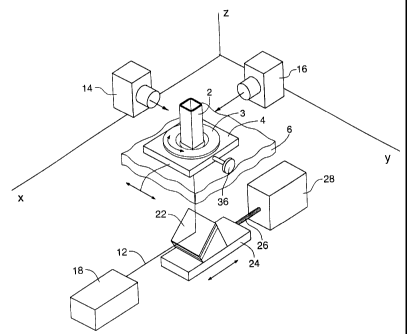
As illustrated schematically in Fig. 1, a transparent lens container 2
carrying a vertebrate eye lens I is mounted on a turntable 3 on a platform 4
which sits
upon a support surface 6 and is slidable in the ydirection via adjustment knob
36 which
rotates a lead screw 37. The lens container will be described in greater
detail later, but
essentially it carries a lens horizontally, i.e. with the lens axis vertical,
within a culture
medium. A laser 18 projects a beam 12, which is reflected upwardly through the
bottom
of the container and thence through the lens by a mirror 22. The mirror is
mounted on
a sliding carriage 24, which is movable in the xdirection via a drive screw 26
driven by
a motor 28, such that this movement causes the laser beam to travel across the
lens
-7-
CA 02297368 2000-01-27
in the x direction. Before the motor 28 is operated to step or scan the laser
beam
across the lens in the x direction, the lens is aligned manually via the
adjustment knob
36, so that the path of the laser beam will be approximately through the lens
axis.
Preferably this alignment is with the assistance of an alignment camera 16
looking at
the container in the x direction, which produces an image of the laser beam
passing
through the lens. Proper alignment is indicated when the laser beam passes
straight
through the lens from that vantage point, rather than being deviated by the
lens.
Alternatively, the alignment could be done visually, but the alignment camera
simplifies
this task and avoids parallax errors.
Once the lens is properly aligned, the laser beam is scanned or stepped
across the lens in the x direction by operation of the motor 28. The images of
the
beams are captured by an analysis camera 14 which looks at the container in
the y
direction. As the laser is stepped across the diameter of the lens, the
refraction of the
beam is clearly visible within the container, since the culture medium
suspends fine
particles which are illuminated by the laser beam. Analysis of the data will
be
discussed in greater detail later below.
Although the laser 18 could be positioned directly under the lens
container to project its beam upwardly, it is preferable to position it
horizontally and use
the sliding mirror. This produces a more compact unit, avoids movement of the
laser
itself, and avoids possible damage to the laser from any spillage from the
lens
container.
The turntable 3 permits the userto rotate the lens through ninety degrees,
if analysis of the lens is desired in two planes. Operation of the turntable
is manual in
the preferred embodiment, although clearly that could be automated if desired.
A particular advantage of the invention is that it may be configured quite
compactly within a readily portable case. The support surface 6 in the
preferred
embodiment is mounted across a base 40, and all mechanical and electrical
parts other
than the lens container 2, turntable 3, platform 4, and cameras 14, 16, can be
located
beneath the support surface 6. A lid 42 is positionable on the base,
preferably sealed
with a foam strip 43 to prevent ambient light from entering the case.
-8-
CA 02297368 2000-01-27
Lens container
The lens container 2 will now be described in greater detail, with
reference to Figs. 9-11 in particular. The container has transparent side
walls
extending upwardly from a rubber base unit 50, forming a glass tube 52 with a
square
cross-section. The glass tube is sealed to the rubber base unit, by virtue of
a tight fit
over a correspondingly shaped upward projecting block portion 51 of the base
unit.
The base unit in turn seals into a recess in the turntable 3. A flat glass
disk 54 is
sealed across the inside of the block portion. The block portion has four
corner posts
53 projecting upwardly therefrom. A lens seating washer 56 sits on notches on
the
corner posts, to support the lens 1. Washers with central openings of
different
diameters may be used for different diameter lenses.
To place a lens in the container so that it may be scanned, the glass tube
52 is removed from the base unit, the lens I is placed upon the washer 56.
Once the
lens is in place, the glass tube is placed over the lens and is pressed into
place on the
block portion 51, such that a liquid-tight seal is formed. Once this seal is
formed, the
culture medium is added to the container. Optionally a Petri dish 64 or other
suitable
cover is then placed atop the container to prevent bacteria and other
contaminants from
entering the tube. The lens container is oriented relative to the laser beam
such that
the laser beam is projected through the bottom transparent portion, then the
lens,
parallel to the lens optical axis. The central transparent portion of the
container is
aligned with the field of view of the cameras, with the flat sidewalls of the
glass tube 52
facing directly at the cameras, in order to minimize the refraction effects
while looking
through the sidewalls.
Data Capture and Analysis
Using the apparatus of the invention, the method could be carried out
using prior art analysis techniques such as those described in the Gershon et
al. prior
art. However, it is preferable to used the advanced analysis techniques
described
below, which are embodied in software.
As the laser is stepped across the lens after being suitably aligned
(whether with the aid of an alignment camera 16 or otherwise), the actual
position and
-9-
CA 02297368 2000-01-27
slope of each beam is captured by the analysis camera 14. When all steps
across the
lens have been made, the captured data for each step position is used to
calculate the
back vertex distance of each position and the differences in that measurement
at
various positions, as well as the equivalent focal length. This procedure
eliminates the
need for the iterative pre-processing step used in the prior art Gershon et
al. apparatus.
The nature of the data which is retrieved from the analysis camera is as
follows:
Preferably, the analysis camera focuses incoming light onto a
semiconductor wafer that is structured as an array of light sensitive elements
or pixels.
In the preferred embodiment, the camera has an array 320 pixels wide by 240
pixels
high. Each pixel, when exposed to light, accumulates a voltage proportional to
the
amount of light striking that pixel. The circuits within the camera later
extract the voltage
on each pixel in turn and convert them into digital values from zero (0), for
a dark pixel,
to two hundred and fifty five (255) for a brightly lit pixel.
The camera outputs its data one line of pixels at a time. That is, in order
to read the whole image the controller board must retrieve 240 lines of 320
pixels. That
is, in order to process an entire image a total of 76,800 pixels must be
retrieved.
For operation of the preferred embodiment, only a subset of these data
need to be transferred to the program. Fig. 12 shows a section of the camera
image
array that is typically encountered while looking for a laser beam. The image
of the
laser beam is projected onto the camera array. This causes a few pixels to
have a
significantly higher value than those outside the beam. Some pixels apparently
outside
the beam also occasionally have values that are alarmingly high. These may be
caused
by internal reflections in the camera, sparkles in the lens fluid, or flaws in
the camera
matrix. The software accounts for this phenomenon by preprocessing the data
within
the scanner during line-finding operations. Instead of transmitting the whole
image
array to the processing application, the microprocessor within the scanner bed
examines each line as it receives it from the camera and detects where the
brightest
pixel is on that line. It then transmits only the relative pixel location on
the line and the
brightness at that point to the application.
Further preprocessing defined as the "sum of line" occurs during the
operation to define back vertex locations along the lens. It involves
analysing each line
-10-
CA 02297368 2000-01-27
of the image from the top to the bottom. Looking at each line of the image
from top to
bottom where the image of the beam hits the camera array, the majority of the
lines
have a narrow bright spot. However, when the lens itself comes into view, the
laser
brightness spreads at the lens surface, causing the lens surface to "light
up", permitting
location of the back vertex. The software uses this characteristic to perform
another
preprocessing simplification. When in this mode the microprocessor retrieves
and
sums every pixel on each line and returns that sum for each line
The application program uses the back vertex of the lens as the reference
plane from which the focal length of each beam is calculated. When a scan is
started
by the user the software uses the scanner to determine the location of this
point.
The scanner is first commanded to position the laser in the nominal center
of the lens. The laser is then turned on and the scanner is commanded to
provide the
application with "sum of line" data. That is, the scanner causes the camera to
capture
a frame and retrieves the data from the camera, summing the pixels for each
line and
returning those sums to the application.
The application then calculates a differential curve for all of the data. This
differential generates a peak value at the point where the back vertex of the
lens comes
into view. The program then remembers this location for later calculation and
uses it
as the lowest point to search for lines in the line finder.
Additionally, the routine also examines the upper part of the frame looking
for bright spots in the top of the lens holder. This information is used to
set the upper
field of view for the line finder. When the back vertex and field of view has
been
determined the application then starts the scan sequence. The first step is to
find the
centerline of the camera. This line or beam is present at the start since the
laser was
already positioned to determine the back vertex distance. This operation is
performed
to calculate the skew on the camera caused by manufacturing inconsistencies.
This
value is later used to adjust the beam data. Having examined the centerline
the laser
is offset to the side of the lens by half of the scanning distance across the
lens as
chosen by the user.
The beam location and angle is determined, then the laser repositioned
by the step size and the sequence repeated. Once all steps have been measured,
the
beam data is processed to determine the focal length of each beam relative to
the back
-11-
CA 02297368 2000-01-27
vertex, the average focal length and standard deviation and error of the mean.
Additionally, similar results for the relative intensity of the beam are also
calculated.
The critical element of the scanning software is the line finder algorithm.
These routines are responsible for determining the location and angle of the
beam. The
routine examines the data retrieved from the scanner. This data is in the form
of
maximum pixel per line. That is, for every line in the field of view, the
scanner returns
the relative location of the brightest pixel and its intensity. The line
finder stores this
information in an array and scans through this array in an attempt to sanitize
the
results.
Since noise or bright spots in the fluid can cause some lines to be
incorrectly reported, the line finder must examine each line with respect to
the rest to
determine if the data for that line is consistent. If it is not, then the
routine attempts to
relocate the data for that line within range of the rest. This technique
significantly
improves the ability to detect lines in noisy data. Once sufficient cleaning
is done to the
data the routine examines the data again and groups successive data that
appear to
be on a line into segments, The slope and position of each segment is
computed. If
multiple segments are found, each is compared with the other to determine if
they fall
on the same extrapolated line. If they do the line segments are joined to form
a single
line.
At the end of this process a single line will have been identified (if
possible). The line data is then converted to metric measurements using the
pre-
calibrated scale of the camera.
After the scan data has been retrieved certain post processing activities
take place to compensate for errors in the system. First the skew of the
camera is
removed by rotating the data an amount equal to but in the other direction to
the skew
of the centerline measured at the start of the scanning process. Next, and if
enabled
by the user, The software attempts to shift the data relative to the center of
lens to such
that the average focal length of all beams to the left of center match those
to the right
of center. This operation corrects for slight errors in initial positioning.
Because of inconsistencies and inaccuracies in the construction of the
scanner and the cameras themselves, the scanner and application software are
required to adjust the data to compensate for these errors. The application
uses
-12-
~_._
CA 02297368 2000-01-27
information that is stored in non-volatile memory within the scanner itself.
This
information is loaded into the device by running the calibration program that
ships with
the unit.
The invention includes the further procedure of applying a stimulus to the
lens in the culture medium, waiting a period of time, further projecting a
laser beam
through the lens at different positions across the lens and repeating the
above steps
and then comparing the focal length, focal length variance (spherical
aberration) and
transparency of the lens before and after that period of time, so as to
determine the
irritancy of the lens to the stimulus.
It will be appreciated that the above description relates to the preferred
embodiment by way of example only. Many variations on the invention will be
obvious
to those knowledgeable in the field, and such obvious variations are within
the scope
of the invention as described and claimed, whether or not expressly described.
-13-