Language selection

Search

Patent 2297877 Summary

Third-party information liability

Some of the information on this Web page has been provided by external sources. The Government of Canada is not responsible for the accuracy, reliability or currency of the information supplied by external sources. Users wishing to rely upon this information should consult directly with the source of the information. Content provided by external sources is not subject to official languages, privacy and accessibility requirements.

Claims and Abstract availability

Any discrepancies in the text and image of the Claims and Abstract are due to differing posting times. Text of the Claims and Abstract are posted:

  • At the time the application is open to public inspection;
  • At the time of issue of the patent (grant).
(12) Patent Application: (11) CA 2297877
(54) English Title: GROUND WIRE FOR TRANSMISSION SYSTEMS
(54) French Title: FIL DE TERRE POUR RESEAUX DE TRANSPORT D'ENERGIE
Status: Deemed Abandoned and Beyond the Period of Reinstatement - Pending Response to Notice of Disregarded Communication
Bibliographic Data
(51) International Patent Classification (IPC):
  • H01B 11/22 (2006.01)
  • H01B 09/00 (2006.01)
  • H02G 07/22 (2006.01)
  • H02J 04/00 (2006.01)
(72) Inventors :
  • AKASAKA, HIROJI (Canada)
  • HUOT, MICHEL (Canada)
  • SHINOHARA, TAKASHI (Canada)
  • SINGH, TARLOCHAN (Canada)
  • CHOO-WING, CARLTON (Canada)
  • SCHEHADE, TEWFIK (Canada)
(73) Owners :
  • PHILLIPS-FITEL INC.
(71) Applicants :
  • PHILLIPS-FITEL INC. (Canada)
(74) Agent: FASKEN MARTINEAU DUMOULIN LLP
(74) Associate agent:
(45) Issued:
(22) Filed Date: 2000-02-03
(41) Open to Public Inspection: 2001-08-03
Examination requested: 2001-04-12
Availability of licence: N/A
Dedicated to the Public: N/A
(25) Language of filing: English

Patent Cooperation Treaty (PCT): No

(30) Application Priority Data: None

Abstracts

English Abstract


A ground wire for a power transmission system has a plastic tube to carry a
bundle of optical fibers. The plastic tube is clad with a metal strip,
preferably aluminum,
and is supported by a set of wire strands disposed about the tube.


Claims

Note: Claims are shown in the official language in which they were submitted.

We claim:
1. A ground wire for use in an above ground power transmission system, said
ground wire comprising an elongate plastics tube, at least one fiber optic
cable
freely moveable within said tube and having an overall length not less than
0.1
greater than said tube in a free body state, a metal cladding encompassing
said
tube and a plurality of metal wire strands disposed about said cladding and
extending along the length of said tube.
2. A ground wire according to claim 1 wherein said cladding and said strands
are of
similar metal.
3. A ground wire according to claim 2 wherein said cladding is aluminum.
4. A ground wire according to claim 3 wherein said strands are aluminum alloy.
5. A ground wire according to claim 3 wherein said cladding is adhered to said
tube.
6. A ground wire according to claim 5 wherein said adhesive is activated by
high
frequency radiation.
7. A ground wire according to claim 5 wherein said cladding is adhered to said
tube
by an adhesive selected from the group comprising a liquid adhesive and a
solid
adhesive.
8. A ground wire according to claim 1 wherein said plastic tube exhibits a
longitudinal elasticity greater than 1%.
9. A ground wire according to claim 1 wherein said plastic tube is formed from
a
plastic selected from the group consisting of polycarbonate and PBT.
10. A ground wire according to claim 1 wherein said plastic tube has a wall
thickness
sufficient to withstand radial loads imposed thereon during installation.
11. A ground wire according to claim 10 wherein said plastic tube has an
outside
diameter between 2 mm and 7 mm and a wall thickness of between 0.7 mm and
2.5 mm.
12. A ground wire according to claim 11 wherein said aluminum cladding is
coextensive with an outer surface of said tube.
6

13. A ground wire according to claim 12 wherein said aluminum cladding has a
thickness of 0.5 mm to 0.7 mm.
14. A ground wire according to claim 1 wherein said fiber is marked
periodically to
allow identification thereof at spaced intervals along said wire.
15. A wire according to claim 14 wherein a plurality of fibers is located
within said
tube and each of said plurality is of a different colour.
16. A method of forming a ground wire for use with a power transmission
system,
said method comprising the steps of inserting at least one optical fiber into
an
elongate plastic tube so as to be freely movable therein in a relaxed
condition,
forming an metal cladding about said tube and apply a plurality of metal
strands
to the exterior of said clad tube.
17. A method according to claim 16 wherein said metal cladding is formed about
said
tube by rolling a metal strip about said tube.
18. A method according to claim 17 including the step of adhering said strip
to said
tube.
19. A method according to claim 16 including the step of elongating said tube
as said
fiber is inserted and subsequently relaxing said tube to provide an excess
length of
said optic fiber in said tube.
7

Description

Note: Descriptions are shown in the official language in which they were submitted.


CA 02297877 2000-02-03
Ground Wire for Transmission Systems
The present invention relates to ground wires for use in an above ground power
transmission systems.
Electrical power is distributed through high voltage wires carned above ground
on pylons. The wires themselves are not insulated and are connected to the
supporting
pylons through an insulating structure. A ground wire is carried between the
pylons
above the conductors to electrically interconnect the pylons and also provide
protection to
the conductor from disturbances such as lightning and other atmospheric
conditions.
The service requirements for the ground wire require it to be electrically
conductive as well as self supporting. In more recent years use has been made
of the
ground wire to also carry optical fibers so that information can be
transmitted along the
existing power transmission routes. The wires have been located within a
conductive,
usually aluminum, tube which in turn is supported by wire strands that provide
the tensile
strength for the ground wire. Because the ground wire is unsupported between
the
pylons, it is subject to the normal mechanical forces due to its own inherent
weight, wind
and other atmospheric conditions such as ice build up. These mechanical forces
are
imposed on the wire strands and the aluminum tube which in turn transmit the
forces
through to the optic fibers.
To avoid the possibility of damage to the fibers it is known to arrange the
fibers
helically on a spacer within the tube. Such an arrangement is relatively
expensive due to
the need of the additional components and the need to assemble the fiber onto
the spacer.
As an alternative to a helical spacer it is also known to ensure that an
excess length of
fiber is provided within the tube so that as the fiber is not subjected to
elongation due to
the mechanical forces, placed on the tube.
The use of the aluminum tube not only protects the fibers from water but also
provides a conduction path between the pylons. However, the aluminum tube is
relatively weak in compression and therefore is unable to withstand the radial
forces that

CA 02297877 2000-02-03
might be imposed upon it during installation and connection of supporting
hardware.
Typically the wire is fed to the pylons over pulleys and is subsequently
clamped to the
pylons, both of which result in a significant radial loading on the tube. To
provide
additional mechanical strength it has been proposed to utilize concentric
rings of
aluminum wires around the aluminum tube. Typically these wires are steel with
an
aluminum cladding adjacent the tube and an aluminum alloy as a second band
ofwires.
The increased tensile and radial strengths avoid damage to the tube but at the
same time
increases the expense of the ground wire.
A further solution that has been proposed is to utilize a stainless steel tube
with
either a stranded or loose strand of fiber within the tube. The stainless
steel tube is
surrounded by aluminum alloy or aluminum clad wires to provide the necessary
conductivity. However the interface between the aluminum wires and stainless
steel tube
leads to a galvanic action and corrosion over an extended period.
It is therefore an object of the present invention to provide a ground wire in
which
the above disadvantages are obviated or mitigated.
In accordance with one aspect of the present invention there is provided a
ground
wire for use in an above ground power transmission system. The ground wire
comprises
an elongate plastics tube and at least one fiber optic cable freely moveable
within said
tube and having an overall length greater than the tube in a free body state.
A metal
cladding encompasses the tube and a plurality of metal wire strands are
disposed about
the cladding and extend along the length of said tube.
The provision of a plastic tube to house the optic fibers enables the
requisite radial
strength to be attained with the metal cladding that is preferably aluminum,
providing the
necessary conductivity.
According to a further aspect of the present invention there is provided a
method
of forming a ground wire for use with a power transmission system the method
comprises
2

CA 02297877 2000-02-03
the steps of inserting at least one optical fiber into an elongate plastic
tube so as to be
freely moveable therein in a relaxed condition and forming a metal cladding
about the
tube. A plurality of metal strands are then applied to the exterior of the
clad tube.
Preferably the metal cladding is an aluminum strip that is rolled about the
tube to
encompass the plastic tube.
An embodiment of the invention will now be described by way of example only
with reference to the accompanying drawings in which:-
Figure 1 is a schematic illustration of a power transmission system.
Figure 2 is a perspective view of a portion of the ground wire used in the
power
transmission system of figure 1.
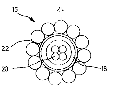
Figure 3 is an end view of the ground wire shown in figure 2.
Figure 4 is an enlarged view of a portion of the wire shown in figure 2.
Figure 5 is a schematic representation of a step in the manufacture in the
ground wire of
figure 2.
Figure 6 is a graph showing the variation of temperature across a component of
the wire
shown in figure 2.
Referring therefore to Figure 1, an electrical power transmission system
generally
indicated at 10 includes a pair of pylons 12 supporting high-tension phase
conductors 14.
A ground wire 16 extends between the pylons 12 above the conductors 14 between
each
of the pylons. The ground wire 16 is fixed at each of the pylons 12 by
suitable clamps
and provides a continuous conductive path between the pylons.
The ground wire 16 is shown in more detail in figures 2 and 3 and includes a
plastics tube 18 in which are a number of optic fibers 20. The optic fibers
are utilized to
carry information and typically the tube will carry a significant number of
fibers,
sometimes upwards of 200. The fibers 20 are loosely located within the tube 18
and, in a
free body state, have an excess length greater than the length of the tube. In
one
3

CA 02297877 2000-02-03
embodiment this excess length is about 0.1% to 0.3%. In this way the tube 18
may
elongate without inducing a corresponding strain upon the fibers 20. As can be
seen in
figure 4, the fibers 20 are marked with ring markings 21 that are applied at
periodic
intervals. The markings are distinguishable from one another by varying the
number and
colour of the markings to allow the same fiber to be identified at opposite
ends of the
wire 16. One of the fibers, 20a is marked periodically with a single ring,
another 20b is
marked with a double ring and a further 20c is marked with a triple ring. The
rings may
all be the same colour or may be different colours or combinations of colours
to allow
each fiber to be marked uniquely. In addition, each of the fibers themselves
may be
different colours to allow each type of marking, 1 ring, 2-ring etc. to
identify more than
one fiber.
An metal cladding 22 encompasses the tube 18 to provide an electrically
conductive path along the tube. The metal cladding is preferably formed from
aluminum
to provide a high conductivity and closely conforms to the outer wall of the
tube 18.
A plurality of wire strands 24 are helically wound around the outside of the
tube
22. The strands 24 are typically a steel wire 26 having an aluminum coating 28
and an
aluminum alloy strand 27. The strands 24 provide the requisite tensile
strength for the
tube to span between the pylons 12 and provide similar surface material to the
cladding to
inhibit galvanic action.
The tube 18 is formed from a plastics material having a relatively high
modulus of
elongation to permit extension greater than 1 % and typically in the order of
6%. The
extension can be approximately 10 times the excess length of the fibres 20.
The tube is
formed from an engineering thermoplastic, typically polycarbonate or
polybutylene
terephtalate (PBT) or polyethylene terephthalate (PET) or polyethylene
napthalate (PEN).
In the preferred embodiment tube 18 has a diameter of between 2 and 7
millimeters and a
wall thickness of between 0.7 and 2.5 millimeter.
4

CA 02297877 2000-02-03
The metallic coating 22 is preferably an aluminum tape rolled about the
plastic
tube 18 having a thickness in the order of 0.5 to 0.7 millimeters. As shown in
figure 4,
the metallic cladding 22 is wrapped around the plastic tube 18 as the tube is
pulled
through supporting rollers. The material 22 closely conforms to the outer
surface of the
tube 18 and provides a continuous seam at opposite edges of the tape. The tape
abuts the
outer surface of the tube 18 and may be adhered to the wall of the tube by a
liquid or
solid adhesive 29 applied to the tape or subsequently activated by high
frequency or heat.
The wire strands 24 are chosen to be of sufficient diameter and number to
provide
the tensile strength required for the span between the pylons 12 and may if
preferred be
arranged in 2 annular bands.
In use, the tube 18 has sufficient radial strength to withstand the radial
loads
imposed on the cable due to the clamping at the pylon or installation over a
pulley. At
the same time the plastic tube provides protection for the fibers from water
and ice and
the excess length of the fibers in the tubes prevents strain being induced in
the fibers
when the ground wire is subject to mechanical loading.
The tube 18 is also effective to prevent overheating in the event a short
circuit is
experienced in the strands 24. As can be seen from figure 6, the tube 18 is
effective to
maintain a significant temperature difference of about 100 degrees between the
inside
temperature 30 and outside temperature 32 of the tube 18 when the outside
surface of the
tube 18 is subjected to a temperature of 300° C.
It will be appreciated that the dimensions noted above with respect to the
preferred embodiment are exemplary only and the individual components may be
adjusted to suit the particular mechanical requirements of a given
installation.
5

Representative Drawing
A single figure which represents the drawing illustrating the invention.
Administrative Status

2024-08-01:As part of the Next Generation Patents (NGP) transition, the Canadian Patents Database (CPD) now contains a more detailed Event History, which replicates the Event Log of our new back-office solution.

Please note that "Inactive:" events refers to events no longer in use in our new back-office solution.

For a clearer understanding of the status of the application/patent presented on this page, the site Disclaimer , as well as the definitions for Patent , Event History , Maintenance Fee  and Payment History  should be consulted.

Event History

Description Date
Inactive: IPC from MCD 2006-03-12
Application Not Reinstated by Deadline 2003-12-01
Inactive: Dead - No reply to s.30(2) Rules requisition 2003-12-01
Deemed Abandoned - Failure to Respond to Maintenance Fee Notice 2003-02-03
Inactive: Abandoned - No reply to s.30(2) Rules requisition 2002-11-29
Inactive: S.30(2) Rules - Examiner requisition 2002-07-29
Application Published (Open to Public Inspection) 2001-08-03
Inactive: Cover page published 2001-08-02
Letter Sent 2001-05-17
Letter Sent 2001-05-16
Inactive: Applicant deleted 2001-05-15
Request for Examination Requirements Determined Compliant 2001-04-12
All Requirements for Examination Determined Compliant 2001-04-12
Request for Examination Received 2001-04-12
Inactive: Correspondence - Formalities 2001-04-05
Inactive: Single transfer 2001-04-05
Revocation of Agent Requirements Determined Compliant 2001-02-07
Inactive: Office letter 2001-02-07
Appointment of Agent Requirements Determined Compliant 2001-02-07
Inactive: Correspondence - Formalities 2001-02-01
Revocation of Agent Request 2001-01-25
Appointment of Agent Request 2001-01-25
Inactive: IPC assigned 2000-04-20
Inactive: First IPC assigned 2000-04-20
Inactive: Filing certificate - No RFE (English) 2000-03-10
Application Received - Regular National 2000-03-03

Abandonment History

Abandonment Date Reason Reinstatement Date
2003-02-03

Maintenance Fee

The last payment was received on 2002-02-01

Note : If the full payment has not been received on or before the date indicated, a further fee may be required which may be one of the following

  • the reinstatement fee;
  • the late payment fee; or
  • additional fee to reverse deemed expiry.

Patent fees are adjusted on the 1st of January every year. The amounts above are the current amounts if received by December 31 of the current year.
Please refer to the CIPO Patent Fees web page to see all current fee amounts.

Fee History

Fee Type Anniversary Year Due Date Paid Date
Application fee - standard 2000-02-03
Registration of a document 2001-04-05
Request for examination - standard 2001-04-12
MF (application, 2nd anniv.) - standard 02 2002-02-04 2002-02-01
Owners on Record

Note: Records showing the ownership history in alphabetical order.

Current Owners on Record
PHILLIPS-FITEL INC.
Past Owners on Record
CARLTON CHOO-WING
HIROJI AKASAKA
MICHEL HUOT
TAKASHI SHINOHARA
TARLOCHAN SINGH
TEWFIK SCHEHADE
Past Owners that do not appear in the "Owners on Record" listing will appear in other documentation within the application.
Documents

To view selected files, please enter reCAPTCHA code :


To view images, click a link in the Document Description column (Temporarily unavailable). To download the documents, select one or more checkboxes in the first column and then click the "Download Selected in PDF format (Zip Archive)" or the "Download Selected as Single PDF" button.

List of published and non-published patent-specific documents on the CPD .

If you have any difficulty accessing content, you can call the Client Service Centre at 1-866-997-1936 or send them an e-mail at CIPO Client Service Centre.

({010=All Documents, 020=As Filed, 030=As Open to Public Inspection, 040=At Issuance, 050=Examination, 060=Incoming Correspondence, 070=Miscellaneous, 080=Outgoing Correspondence, 090=Payment})


Document
Description 
Date
(yyyy-mm-dd) 
Number of pages   Size of Image (KB) 
Representative drawing 2001-08-01 1 7
Claims 2000-02-02 2 72
Description 2000-02-02 5 236
Abstract 2000-02-02 1 8
Drawings 2000-02-02 3 189
Drawings 2001-01-31 3 46
Filing Certificate (English) 2000-03-09 1 163
Request for evidence or missing transfer 2001-02-05 1 108
Acknowledgement of Request for Examination 2001-05-16 1 178
Courtesy - Certificate of registration (related document(s)) 2001-05-15 1 113
Reminder of maintenance fee due 2001-10-03 1 116
Courtesy - Abandonment Letter (R30(2)) 2003-02-09 1 167
Courtesy - Abandonment Letter (Maintenance Fee) 2003-03-02 1 179
Correspondence 2000-03-09 1 19
Correspondence 2001-01-24 2 53
Correspondence 2001-02-06 1 9
Correspondence 2001-02-06 1 10
Correspondence 2001-01-31 4 72
Correspondence 2001-04-04 1 38
Correspondence 2001-04-04 1 41
Fees 2002-01-31 1 24