Sélection de la langue

Search

Sommaire du brevet 2297877 

Énoncé de désistement de responsabilité concernant l'information provenant de tiers

Une partie des informations de ce site Web a été fournie par des sources externes. Le gouvernement du Canada n'assume aucune responsabilité concernant la précision, l'actualité ou la fiabilité des informations fournies par les sources externes. Les utilisateurs qui désirent employer cette information devraient consulter directement la source des informations. Le contenu fourni par les sources externes n'est pas assujetti aux exigences sur les langues officielles, la protection des renseignements personnels et l'accessibilité.

Disponibilité de l'Abrégé et des Revendications

L'apparition de différences dans le texte et l'image des Revendications et de l'Abrégé dépend du moment auquel le document est publié. Les textes des Revendications et de l'Abrégé sont affichés :

  • lorsque la demande peut être examinée par le public;
  • lorsque le brevet est émis (délivrance).
(12) Demande de brevet: (11) CA 2297877
(54) Titre français: FIL DE TERRE POUR RESEAUX DE TRANSPORT D'ENERGIE
(54) Titre anglais: GROUND WIRE FOR TRANSMISSION SYSTEMS
Statut: Réputée abandonnée et au-delà du délai pour le rétablissement - en attente de la réponse à l’avis de communication rejetée
Données bibliographiques
(51) Classification internationale des brevets (CIB):
  • H01B 11/22 (2006.01)
  • H01B 09/00 (2006.01)
  • H02G 07/22 (2006.01)
  • H02J 04/00 (2006.01)
(72) Inventeurs :
  • AKASAKA, HIROJI (Canada)
  • HUOT, MICHEL (Canada)
  • SHINOHARA, TAKASHI (Canada)
  • SINGH, TARLOCHAN (Canada)
  • CHOO-WING, CARLTON (Canada)
  • SCHEHADE, TEWFIK (Canada)
(73) Titulaires :
  • PHILLIPS-FITEL INC.
(71) Demandeurs :
  • PHILLIPS-FITEL INC. (Canada)
(74) Agent: FASKEN MARTINEAU DUMOULIN LLP
(74) Co-agent:
(45) Délivré:
(22) Date de dépôt: 2000-02-03
(41) Mise à la disponibilité du public: 2001-08-03
Requête d'examen: 2001-04-12
Licence disponible: S.O.
Cédé au domaine public: S.O.
(25) Langue des documents déposés: Anglais

Traité de coopération en matière de brevets (PCT): Non

(30) Données de priorité de la demande: S.O.

Abrégés

Abrégé anglais


A ground wire for a power transmission system has a plastic tube to carry a
bundle of optical fibers. The plastic tube is clad with a metal strip,
preferably aluminum,
and is supported by a set of wire strands disposed about the tube.

Revendications

Note : Les revendications sont présentées dans la langue officielle dans laquelle elles ont été soumises.


We claim:
1. A ground wire for use in an above ground power transmission system, said
ground wire comprising an elongate plastics tube, at least one fiber optic
cable
freely moveable within said tube and having an overall length not less than
0.1
greater than said tube in a free body state, a metal cladding encompassing
said
tube and a plurality of metal wire strands disposed about said cladding and
extending along the length of said tube.
2. A ground wire according to claim 1 wherein said cladding and said strands
are of
similar metal.
3. A ground wire according to claim 2 wherein said cladding is aluminum.
4. A ground wire according to claim 3 wherein said strands are aluminum alloy.
5. A ground wire according to claim 3 wherein said cladding is adhered to said
tube.
6. A ground wire according to claim 5 wherein said adhesive is activated by
high
frequency radiation.
7. A ground wire according to claim 5 wherein said cladding is adhered to said
tube
by an adhesive selected from the group comprising a liquid adhesive and a
solid
adhesive.
8. A ground wire according to claim 1 wherein said plastic tube exhibits a
longitudinal elasticity greater than 1%.
9. A ground wire according to claim 1 wherein said plastic tube is formed from
a
plastic selected from the group consisting of polycarbonate and PBT.
10. A ground wire according to claim 1 wherein said plastic tube has a wall
thickness
sufficient to withstand radial loads imposed thereon during installation.
11. A ground wire according to claim 10 wherein said plastic tube has an
outside
diameter between 2 mm and 7 mm and a wall thickness of between 0.7 mm and
2.5 mm.
12. A ground wire according to claim 11 wherein said aluminum cladding is
coextensive with an outer surface of said tube.
6

13. A ground wire according to claim 12 wherein said aluminum cladding has a
thickness of 0.5 mm to 0.7 mm.
14. A ground wire according to claim 1 wherein said fiber is marked
periodically to
allow identification thereof at spaced intervals along said wire.
15. A wire according to claim 14 wherein a plurality of fibers is located
within said
tube and each of said plurality is of a different colour.
16. A method of forming a ground wire for use with a power transmission
system,
said method comprising the steps of inserting at least one optical fiber into
an
elongate plastic tube so as to be freely movable therein in a relaxed
condition,
forming an metal cladding about said tube and apply a plurality of metal
strands
to the exterior of said clad tube.
17. A method according to claim 16 wherein said metal cladding is formed about
said
tube by rolling a metal strip about said tube.
18. A method according to claim 17 including the step of adhering said strip
to said
tube.
19. A method according to claim 16 including the step of elongating said tube
as said
fiber is inserted and subsequently relaxing said tube to provide an excess
length of
said optic fiber in said tube.
7

Description

Note : Les descriptions sont présentées dans la langue officielle dans laquelle elles ont été soumises.

CA 02297877 2000-02-03
Ground Wire for Transmission Systems
The present invention relates to ground wires for use in an above ground power
transmission systems.
Electrical power is distributed through high voltage wires carned above ground
on pylons. The wires themselves are not insulated and are connected to the
supporting
pylons through an insulating structure. A ground wire is carried between the
pylons
above the conductors to electrically interconnect the pylons and also provide
protection to
the conductor from disturbances such as lightning and other atmospheric
conditions.
The service requirements for the ground wire require it to be electrically
conductive as well as self supporting. In more recent years use has been made
of the
ground wire to also carry optical fibers so that information can be
transmitted along the
existing power transmission routes. The wires have been located within a
conductive,
usually aluminum, tube which in turn is supported by wire strands that provide
the tensile
strength for the ground wire. Because the ground wire is unsupported between
the
pylons, it is subject to the normal mechanical forces due to its own inherent
weight, wind
and other atmospheric conditions such as ice build up. These mechanical forces
are
imposed on the wire strands and the aluminum tube which in turn transmit the
forces
through to the optic fibers.
To avoid the possibility of damage to the fibers it is known to arrange the
fibers
helically on a spacer within the tube. Such an arrangement is relatively
expensive due to
the need of the additional components and the need to assemble the fiber onto
the spacer.
As an alternative to a helical spacer it is also known to ensure that an
excess length of
fiber is provided within the tube so that as the fiber is not subjected to
elongation due to
the mechanical forces, placed on the tube.
The use of the aluminum tube not only protects the fibers from water but also
provides a conduction path between the pylons. However, the aluminum tube is
relatively weak in compression and therefore is unable to withstand the radial
forces that

CA 02297877 2000-02-03
might be imposed upon it during installation and connection of supporting
hardware.
Typically the wire is fed to the pylons over pulleys and is subsequently
clamped to the
pylons, both of which result in a significant radial loading on the tube. To
provide
additional mechanical strength it has been proposed to utilize concentric
rings of
aluminum wires around the aluminum tube. Typically these wires are steel with
an
aluminum cladding adjacent the tube and an aluminum alloy as a second band
ofwires.
The increased tensile and radial strengths avoid damage to the tube but at the
same time
increases the expense of the ground wire.
A further solution that has been proposed is to utilize a stainless steel tube
with
either a stranded or loose strand of fiber within the tube. The stainless
steel tube is
surrounded by aluminum alloy or aluminum clad wires to provide the necessary
conductivity. However the interface between the aluminum wires and stainless
steel tube
leads to a galvanic action and corrosion over an extended period.
It is therefore an object of the present invention to provide a ground wire in
which
the above disadvantages are obviated or mitigated.
In accordance with one aspect of the present invention there is provided a
ground
wire for use in an above ground power transmission system. The ground wire
comprises
an elongate plastics tube and at least one fiber optic cable freely moveable
within said
tube and having an overall length greater than the tube in a free body state.
A metal
cladding encompasses the tube and a plurality of metal wire strands are
disposed about
the cladding and extend along the length of said tube.
The provision of a plastic tube to house the optic fibers enables the
requisite radial
strength to be attained with the metal cladding that is preferably aluminum,
providing the
necessary conductivity.
According to a further aspect of the present invention there is provided a
method
of forming a ground wire for use with a power transmission system the method
comprises
2

CA 02297877 2000-02-03
the steps of inserting at least one optical fiber into an elongate plastic
tube so as to be
freely moveable therein in a relaxed condition and forming a metal cladding
about the
tube. A plurality of metal strands are then applied to the exterior of the
clad tube.
Preferably the metal cladding is an aluminum strip that is rolled about the
tube to
encompass the plastic tube.
An embodiment of the invention will now be described by way of example only
with reference to the accompanying drawings in which:-
Figure 1 is a schematic illustration of a power transmission system.
Figure 2 is a perspective view of a portion of the ground wire used in the
power
transmission system of figure 1.
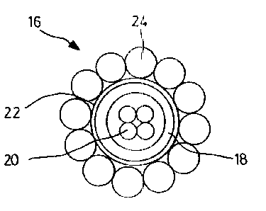
Figure 3 is an end view of the ground wire shown in figure 2.
Figure 4 is an enlarged view of a portion of the wire shown in figure 2.
Figure 5 is a schematic representation of a step in the manufacture in the
ground wire of
figure 2.
Figure 6 is a graph showing the variation of temperature across a component of
the wire
shown in figure 2.
Referring therefore to Figure 1, an electrical power transmission system
generally
indicated at 10 includes a pair of pylons 12 supporting high-tension phase
conductors 14.
A ground wire 16 extends between the pylons 12 above the conductors 14 between
each
of the pylons. The ground wire 16 is fixed at each of the pylons 12 by
suitable clamps
and provides a continuous conductive path between the pylons.
The ground wire 16 is shown in more detail in figures 2 and 3 and includes a
plastics tube 18 in which are a number of optic fibers 20. The optic fibers
are utilized to
carry information and typically the tube will carry a significant number of
fibers,
sometimes upwards of 200. The fibers 20 are loosely located within the tube 18
and, in a
free body state, have an excess length greater than the length of the tube. In
one
3

CA 02297877 2000-02-03
embodiment this excess length is about 0.1% to 0.3%. In this way the tube 18
may
elongate without inducing a corresponding strain upon the fibers 20. As can be
seen in
figure 4, the fibers 20 are marked with ring markings 21 that are applied at
periodic
intervals. The markings are distinguishable from one another by varying the
number and
colour of the markings to allow the same fiber to be identified at opposite
ends of the
wire 16. One of the fibers, 20a is marked periodically with a single ring,
another 20b is
marked with a double ring and a further 20c is marked with a triple ring. The
rings may
all be the same colour or may be different colours or combinations of colours
to allow
each fiber to be marked uniquely. In addition, each of the fibers themselves
may be
different colours to allow each type of marking, 1 ring, 2-ring etc. to
identify more than
one fiber.
An metal cladding 22 encompasses the tube 18 to provide an electrically
conductive path along the tube. The metal cladding is preferably formed from
aluminum
to provide a high conductivity and closely conforms to the outer wall of the
tube 18.
A plurality of wire strands 24 are helically wound around the outside of the
tube
22. The strands 24 are typically a steel wire 26 having an aluminum coating 28
and an
aluminum alloy strand 27. The strands 24 provide the requisite tensile
strength for the
tube to span between the pylons 12 and provide similar surface material to the
cladding to
inhibit galvanic action.
The tube 18 is formed from a plastics material having a relatively high
modulus of
elongation to permit extension greater than 1 % and typically in the order of
6%. The
extension can be approximately 10 times the excess length of the fibres 20.
The tube is
formed from an engineering thermoplastic, typically polycarbonate or
polybutylene
terephtalate (PBT) or polyethylene terephthalate (PET) or polyethylene
napthalate (PEN).
In the preferred embodiment tube 18 has a diameter of between 2 and 7
millimeters and a
wall thickness of between 0.7 and 2.5 millimeter.
4

CA 02297877 2000-02-03
The metallic coating 22 is preferably an aluminum tape rolled about the
plastic
tube 18 having a thickness in the order of 0.5 to 0.7 millimeters. As shown in
figure 4,
the metallic cladding 22 is wrapped around the plastic tube 18 as the tube is
pulled
through supporting rollers. The material 22 closely conforms to the outer
surface of the
tube 18 and provides a continuous seam at opposite edges of the tape. The tape
abuts the
outer surface of the tube 18 and may be adhered to the wall of the tube by a
liquid or
solid adhesive 29 applied to the tape or subsequently activated by high
frequency or heat.
The wire strands 24 are chosen to be of sufficient diameter and number to
provide
the tensile strength required for the span between the pylons 12 and may if
preferred be
arranged in 2 annular bands.
In use, the tube 18 has sufficient radial strength to withstand the radial
loads
imposed on the cable due to the clamping at the pylon or installation over a
pulley. At
the same time the plastic tube provides protection for the fibers from water
and ice and
the excess length of the fibers in the tubes prevents strain being induced in
the fibers
when the ground wire is subject to mechanical loading.
The tube 18 is also effective to prevent overheating in the event a short
circuit is
experienced in the strands 24. As can be seen from figure 6, the tube 18 is
effective to
maintain a significant temperature difference of about 100 degrees between the
inside
temperature 30 and outside temperature 32 of the tube 18 when the outside
surface of the
tube 18 is subjected to a temperature of 300° C.
It will be appreciated that the dimensions noted above with respect to the
preferred embodiment are exemplary only and the individual components may be
adjusted to suit the particular mechanical requirements of a given
installation.
5

Dessin représentatif
Une figure unique qui représente un dessin illustrant l'invention.
États administratifs

2024-08-01 : Dans le cadre de la transition vers les Brevets de nouvelle génération (BNG), la base de données sur les brevets canadiens (BDBC) contient désormais un Historique d'événement plus détaillé, qui reproduit le Journal des événements de notre nouvelle solution interne.

Veuillez noter que les événements débutant par « Inactive : » se réfèrent à des événements qui ne sont plus utilisés dans notre nouvelle solution interne.

Pour une meilleure compréhension de l'état de la demande ou brevet qui figure sur cette page, la rubrique Mise en garde , et les descriptions de Brevet , Historique d'événement , Taxes périodiques et Historique des paiements devraient être consultées.

Historique d'événement

Description Date
Inactive : CIB de MCD 2006-03-12
Demande non rétablie avant l'échéance 2003-12-01
Inactive : Morte - Aucune rép. dem. par.30(2) Règles 2003-12-01
Réputée abandonnée - omission de répondre à un avis sur les taxes pour le maintien en état 2003-02-03
Inactive : Abandon. - Aucune rép dem par.30(2) Règles 2002-11-29
Inactive : Dem. de l'examinateur par.30(2) Règles 2002-07-29
Demande publiée (accessible au public) 2001-08-03
Inactive : Page couverture publiée 2001-08-02
Lettre envoyée 2001-05-17
Lettre envoyée 2001-05-16
Inactive : Demandeur supprimé 2001-05-15
Exigences pour une requête d'examen - jugée conforme 2001-04-12
Toutes les exigences pour l'examen - jugée conforme 2001-04-12
Requête d'examen reçue 2001-04-12
Inactive : Correspondance - Formalités 2001-04-05
Inactive : Transfert individuel 2001-04-05
Exigences relatives à la révocation de la nomination d'un agent - jugée conforme 2001-02-07
Inactive : Lettre officielle 2001-02-07
Exigences relatives à la nomination d'un agent - jugée conforme 2001-02-07
Inactive : Correspondance - Formalités 2001-02-01
Demande visant la révocation de la nomination d'un agent 2001-01-25
Demande visant la nomination d'un agent 2001-01-25
Inactive : CIB attribuée 2000-04-20
Inactive : CIB en 1re position 2000-04-20
Inactive : Certificat de dépôt - Sans RE (Anglais) 2000-03-10
Demande reçue - nationale ordinaire 2000-03-03

Historique d'abandonnement

Date d'abandonnement Raison Date de rétablissement
2003-02-03

Taxes périodiques

Le dernier paiement a été reçu le 2002-02-01

Avis : Si le paiement en totalité n'a pas été reçu au plus tard à la date indiquée, une taxe supplémentaire peut être imposée, soit une des taxes suivantes :

  • taxe de rétablissement ;
  • taxe pour paiement en souffrance ; ou
  • taxe additionnelle pour le renversement d'une péremption réputée.

Les taxes sur les brevets sont ajustées au 1er janvier de chaque année. Les montants ci-dessus sont les montants actuels s'ils sont reçus au plus tard le 31 décembre de l'année en cours.
Veuillez vous référer à la page web des taxes sur les brevets de l'OPIC pour voir tous les montants actuels des taxes.

Historique des taxes

Type de taxes Anniversaire Échéance Date payée
Taxe pour le dépôt - générale 2000-02-03
Enregistrement d'un document 2001-04-05
Requête d'examen - générale 2001-04-12
TM (demande, 2e anniv.) - générale 02 2002-02-04 2002-02-01
Titulaires au dossier

Les titulaires actuels et antérieures au dossier sont affichés en ordre alphabétique.

Titulaires actuels au dossier
PHILLIPS-FITEL INC.
Titulaires antérieures au dossier
CARLTON CHOO-WING
HIROJI AKASAKA
MICHEL HUOT
TAKASHI SHINOHARA
TARLOCHAN SINGH
TEWFIK SCHEHADE
Les propriétaires antérieurs qui ne figurent pas dans la liste des « Propriétaires au dossier » apparaîtront dans d'autres documents au dossier.
Documents

Pour visionner les fichiers sélectionnés, entrer le code reCAPTCHA :


Pour visualiser une image, cliquer sur un lien dans la colonne description du document (Temporairement non-disponible). Pour télécharger l'image (les images), cliquer l'une ou plusieurs cases à cocher dans la première colonne et ensuite cliquer sur le bouton "Télécharger sélection en format PDF (archive Zip)" ou le bouton "Télécharger sélection (en un fichier PDF fusionné)".

Liste des documents de brevet publiés et non publiés sur la BDBC .

Si vous avez des difficultés à accéder au contenu, veuillez communiquer avec le Centre de services à la clientèle au 1-866-997-1936, ou envoyer un courriel au Centre de service à la clientèle de l'OPIC.

({010=Tous les documents, 020=Au moment du dépôt, 030=Au moment de la mise à la disponibilité du public, 040=À la délivrance, 050=Examen, 060=Correspondance reçue, 070=Divers, 080=Correspondance envoyée, 090=Paiement})


Description du
Document 
Date
(aaaa-mm-jj) 
Nombre de pages   Taille de l'image (Ko) 
Dessin représentatif 2001-08-01 1 7
Revendications 2000-02-02 2 72
Description 2000-02-02 5 236
Abrégé 2000-02-02 1 8
Dessins 2000-02-02 3 189
Dessins 2001-01-31 3 46
Certificat de dépôt (anglais) 2000-03-09 1 163
Demande de preuve ou de transfert manquant 2001-02-05 1 108
Accusé de réception de la requête d'examen 2001-05-16 1 178
Courtoisie - Certificat d'enregistrement (document(s) connexe(s)) 2001-05-15 1 113
Rappel de taxe de maintien due 2001-10-03 1 116
Courtoisie - Lettre d'abandon (R30(2)) 2003-02-09 1 167
Courtoisie - Lettre d'abandon (taxe de maintien en état) 2003-03-02 1 179
Correspondance 2000-03-09 1 19
Correspondance 2001-01-24 2 53
Correspondance 2001-02-06 1 9
Correspondance 2001-02-06 1 10
Correspondance 2001-01-31 4 72
Correspondance 2001-04-04 1 38
Correspondance 2001-04-04 1 41
Taxes 2002-01-31 1 24