Language selection

Search

Patent 2298080 Summary

Third-party information liability

Some of the information on this Web page has been provided by external sources. The Government of Canada is not responsible for the accuracy, reliability or currency of the information supplied by external sources. Users wishing to rely upon this information should consult directly with the source of the information. Content provided by external sources is not subject to official languages, privacy and accessibility requirements.

Claims and Abstract availability

Any discrepancies in the text and image of the Claims and Abstract are due to differing posting times. Text of the Claims and Abstract are posted:

  • At the time the application is open to public inspection;
  • At the time of issue of the patent (grant).
(12) Patent: (11) CA 2298080
(54) English Title: COMBINATION ROOF OR BED HEIGHT LOAD SUPPORT
(54) French Title: COMBINAISON DE TOIT ET DE SUPPORT DE CHARGE A LA HAUTEUR DU CAMION
Status: Deemed expired
Bibliographic Data
(51) International Patent Classification (IPC):
  • B60R 9/06 (2006.01)
  • B60P 3/10 (2006.01)
  • B60P 3/40 (2006.01)
(72) Inventors :
  • DARBY, KEN (United States of America)
(73) Owners :
  • DARBY, KEN (United States of America)
(71) Applicants :
  • DARBY, KEN (United States of America)
(74) Agent: NA
(74) Associate agent: NA
(45) Issued: 2004-03-30
(22) Filed Date: 2000-02-03
(41) Open to Public Inspection: 2001-08-03
Examination requested: 2000-02-03
Availability of licence: Yes
(25) Language of filing: English

Patent Cooperation Treaty (PCT): No

(30) Application Priority Data: None

Abstracts

English Abstract

A combination load support for use as a roof height carrier or pickup box extender that inserts into a standard receiver hitch. The device provides support for one end of ladders, canoes, etc. and the pickup cab or sport utility roof provides support for the other end. When one section of this combination load support is inserted in the opposite direction, long loads extending beyond the pickup truck's tailgate can be supported


French Abstract

Une combinaison de support de charge destinée à être utilisée comme porteur de hauteur de toit ou extenseur de caisse de camionnette qui s'introduit dans un attelage de réception standard. Le dispositif fournit un support pour une extrémité d'échelles, de canoës, etc., et la cabine de camionnette ou le toit utilitaire de sport fournit un support pour l'autre extrémité. Lorsqu'une section de cette combinaison de support de charge est introduite dans la direction opposée, de longues charges s'étendant au-delà du hayon de la camionnette peuvent être supportées.

Claims

Note: Claims are shown in the official language in which they were submitted.


What I claim is:

1. A load support device for attachment to a receiver hitch of a vehicle,
the device
comprising an L-shaped member having a first part and a second part extending
transverse
to the first part, said first part being longer than the second part, said
first part having a
free end selectively attachable to the hitch receiver of the vehicle, said
second part having
a free end selectively attachable to the receiver hitch of the vehicle; and a
support member
for selective attachment to one of the free ends, said support member
including a means
for adjusting the height of the device and tie-down cleats secured thereto;
wherein, in a
first use, the free end of the first part is selectively attached to the
receiver hitch and the
support member is adjustably attached to the free end of the support member is
adjustably
attached to the free end of the second part to support a load at a bed height
of the vehicle
and, in a second use, the free end of the second part is selectively attached
to the receiver
hitch and the support member is adjustably attached to the free end of the
first part for
supporting a load at a roof height of the vehicle.

2. The device in claim 1, said tie-down cleats further comprising rounded
edges so as not to
fray a rope or a strap and has a broad enough opening to accept flat straps
with metal
ends.

3. The device in claim 1, wherein said support member defines a T-shaped
member with
multiple holes on both side of the lower side of the T-shape to allow a pin to
be inserted
through one side of the T-shaped support member, through both sides of the
inserted L-
shaped member, and out through the other side of the T-shaped support member
securing
the load support at the needed height.

7

Description

Note: Descriptions are shown in the official language in which they were submitted.


CA 02298080 2003-11-12
Title: COMBINATION ROOF OR BED HEIGHT LOAD SUPPORT
FIELD OF INVENTION
This invention relates to a combination load support that inserts into a
receiver hitch and can
either support items carried on top of a vehicle or items that extend beyond
the pickup truck box.
BACKGROUND of the INVENTION
Many sport utilities have a rack on the roof for carrying various loads but
often these racks are
not strong enough to carry long loads such as 17-foot canoe or long lumber.
There is also a need
to carry long items such as a ladder or canoe on top of a pickup truck while
carrying other items
in the pickup truck box. Many of the new pickup trucks have larger cabs and in
turn a shorter
pickup box for carrying loads. This present invention relates to a combination
load support that
solves both problems of carrying long loads on top of the roof or elongated
loads that stretch out
behind the pickup truck box.
Various units are available to do either one of these jobs but fail to do both
roof top carrying and
pickup box extending with one device. With a pickup truck it is often an
advantage to carry a
long item such as a ladder at the height of the cab roof so that other items
and tools can be
carried in the pickup truck box.
Prior racks such as US Patent Reg. No. 5,451;088 granted September 19, 1995,
to Broad and US
Patent Reg: No. 5,458,389 granted October 17, 1995, to Young insert into a
receiver hitch and
support a load extending beyond the bed of a truck. Neither will aid in
supporting a load at the
level of the roof. Broad has a pair of eye bolts, one on each end of the load
rest. These eye bolts
would work with a rope but not well with hold-down straps if the straps and
their anchoring
devices are too broad for the eye bolts.
1

CA 02298080 2003-11-12
Young had load holders extending vertically from each end of the horizontal
support bar. They
are welded and not adjustable with no means for fastening a rope or hold-down
straps to secure
the load. Young's load holders have a solid top which would not allow for easy
tie down.
US Patent Registration No. 5,560,666 granted October 1, 1996, to Vieira can
support a load at
the height of the roof but requires a separate unit to support a load
extending from the bed of the
truck. Vieira's two units are welded, are not adjustable, and are awkward to
store.
It would be an advantage to the user if one apparatus could support loads on
the roof of a pickup
or a sport utility and also be adjusted to support loads extending beyond the
tailgate of a pickup
truck box.
This apparatus should be easy to assemble or disassemble and require only a
small amount of
storage space such as behind the seat of a pickup truck.
OBJECTS of the INVENTION
It is an object of the present invention to provide a load support for two
different needs which
prior to this invention required tow separate load supports.
Another aspect of the present invention is to provide a device that is easily
attached to and
detached from the vehicle without the use of special tools and equipment.
This combination roof level load support and pickup box extender makes use of
a standard
receiver hitch.
Still another aspect of this invention is to supply a means to tie down the
load being supported by
this device using hold-down cleats that will not fray a rope or strap and are
wide enough to
accept even flat ends of ratchet tie-down straps.
2

CA 02298080 2000-02-03
It is a further object of this invention to provide a load support for roof
level and bed level of both
sport utility vehicles and pickup trucks and for said device to be adjustable
to accommodate all
models of both types of vehicles.
SUN1NIARY
An apparatus to be used as a load support having a combination of uses. One
use is to support
:l 0 the back end of a long load at roof height where the front end is
supported by the roof of the
vehicle. The other use is to support a long load extending from the pickup
truck box.
This load support apparatus consists of an "L"-shaped device that inserts into
the receiver hitch of
the vehicle and into the vertical tube projecting downward of the "T" bar
which supports the load.
When the short leg of the "L" section is inserted in the receiver hitch the
long leg rises vertically
15 high enough to support the "T" bar at roof height. When the long leg of the
"L" section is
inserted in the receiver hitch, the short leg of the "L" rises vertically
enough to support the "T"
bar at the level of the bed of a pickup truck. The "T" bar and the "L" section
are held in place by
a pin in one of several holes which allows a height adjustment to accommodate
the needed height
of various models of pickup trucks and sport utility vehicles.
20 The "T" bar section has a means to secure the load using hold-down cleats
that are smooth,
rounded and formed to provide a flat area to accommodate hold-down straps or a
rope.
BRIEF DESCRIPTION OF THE DRAWING
Fig. I - Illustrates an exploded perspective view of the load support
positioned to
support roof height loads.
25 Fig. II - Illustrates and exploded perspective view of the load support
positioned to
support pickup truck bed height loads.
3

CA 02298080 2000-02-03
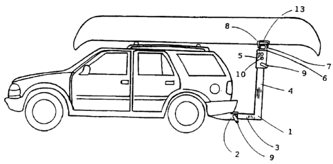
Fig. III - Illustrates a side view of a sport utility vehicle with the
combination load support.
Fig. IV - Illustrates a perspective view of a pickup truck with a combination
load support
adjusted to the roof height.
Fig. V - Illustrates a perspective view of a pickup truck with the combination
load
support adjusted to the bed height.
REFERENCE TO NUMERALS IN DRAWINGS
1. "L" section
2. Insertion hitch
3. Short leg
4. Long Leg
5. Lower Leg
6. "T" lower leg
7. Horizontal support bar
8. Tie down cleats
9. Pin 13.
2.0 10. Adjustment holes
11. Pin keeper
12. Holes
13. Flat area
DETAILED DESCRIPTION OF THE DRAWING
Fig. 1 - Illustrates an exploded view with the "L" section (1) adjusted to
provide roof height
support. The "L" shaped section ( 1 ) has holes ( 12) drilled through both
sides of the tubing at
4

CA 02298080 2000-02-03
both ends of the "L" section ( I ). "L" section ( 1 ) has the long section of
the "L" (4) vertical and
the short leg of the "L" (3) horizontal.
Shown above the "L" section is the "T" support bar (6) having the lower leg
(5) of the "T"
constructed of larger tubing that will slip on the outside of either end of
the "L" section ( I ) drilled
with numerous holes (10) through both sides of the tubing to allow height
adjustments. The "T"
:l0 bar (6) has a horizontal support bar (7) with two tie-down cleats (8), one
at each end. These tie-
down cleats (8) are round to eliminate any fraying and are formed with a flat
area (13) to
accommodate hold-down straps with flat metal ends. The adjustment to proper
height is
accomplished by sliding the "T: (6) with holes (10) over the "L" (1) and
inserting pin (9) when the
holes line up for the desired height of the support bar (7). The keeper pin (
11 ) holds pin (9) in
place.
Fig. II - Illustrates the "L" shaped section of the load support ( 1 )
reversed so as the long leg (4)
of the "L" section is horizontal and the short leg (3) is vertical. The lower
portion (5) of the "T"
bar (6) can be slid around the end of the "L" section (1) as in Fig. I to now
provide support for a
load at a pickup truck bed height.
Fig. III - Illustrates a combination load support with the short leg (3) of
the "L" section (I)
inserted into the receiver hitch and the long leg (4) extending vertically and
inserted into the
bottom (5) of the "T" (6) with a horizontal support bar (7) and smooth tie-
down cleats (8).
The "T" section (6) is adjustable up and down by inserting a pin (9) through
adjustment holes (10)
and the hole (12) of the "L" section (1). The "L" section (1) in the receiver
hitch (2) is held in
place by another pin (9). The pins (9) are retained in place by a keeper pin (
I 1 ). The "L" section
( 1 ) has holes ( 12) drilled through both sides near each end. The "T" bar
(6) has several holes ( 10)

CA 02298080 2000-02-03
drilled through the sides of the lower leg (5) for height adjustment of the
support bar.
Fig. IV - Illustrates the use of this adjustable load support with the short
leg (3) of "L" section (1)
inserted in the insertion hitch (2) and the long leg (4) reaching vertically
to support a roof height
load on the "T" bar (6).
Fig. V - Illustrates the use of this adjustable load support with the long leg
(4) of the "L" section
1l0 (1) inserted in the hitch (2) and the short leg (3) of "L" (1) rising
vertically to accept "T" bar (6)
to support a load at the bed height of the pickup truck.
6

Representative Drawing
A single figure which represents the drawing illustrating the invention.
Administrative Status

For a clearer understanding of the status of the application/patent presented on this page, the site Disclaimer , as well as the definitions for Patent , Administrative Status , Maintenance Fee  and Payment History  should be consulted.

Administrative Status

Title Date
Forecasted Issue Date 2004-03-30
(22) Filed 2000-02-03
Examination Requested 2000-02-03
(41) Open to Public Inspection 2001-08-03
(45) Issued 2004-03-30
Deemed Expired 2017-02-03

Abandonment History

Abandonment Date Reason Reinstatement Date
2003-02-03 FAILURE TO PAY APPLICATION MAINTENANCE FEE 2003-03-14

Payment History

Fee Type Anniversary Year Due Date Amount Paid Paid Date
Request for Examination $200.00 2000-02-03
Application Fee $150.00 2000-02-03
Maintenance Fee - Application - New Act 2 2002-02-04 $50.00 2002-02-04
Reinstatement: Failure to Pay Application Maintenance Fees $200.00 2003-03-14
Maintenance Fee - Application - New Act 3 2003-02-03 $50.00 2003-03-14
Maintenance Fee - Application - New Act 4 2004-02-03 $50.00 2003-11-04
Final Fee $150.00 2004-01-16
Maintenance Fee - Patent - New Act 5 2005-02-03 $100.00 2005-01-21
Maintenance Fee - Patent - New Act 6 2006-02-03 $100.00 2006-02-03
Maintenance Fee - Patent - New Act 7 2007-02-05 $100.00 2006-11-27
Maintenance Fee - Patent - New Act 8 2008-02-04 $100.00 2007-11-15
Maintenance Fee - Patent - New Act 9 2009-02-03 $100.00 2009-01-23
Maintenance Fee - Patent - New Act 10 2010-02-03 $125.00 2010-01-28
Maintenance Fee - Patent - New Act 11 2011-02-03 $125.00 2011-01-28
Maintenance Fee - Patent - New Act 12 2012-02-03 $125.00 2012-01-13
Maintenance Fee - Patent - New Act 13 2013-02-04 $125.00 2013-01-30
Maintenance Fee - Patent - New Act 14 2014-02-03 $125.00 2014-01-27
Maintenance Fee - Patent - New Act 15 2015-02-03 $425.00 2015-05-15
Owners on Record

Note: Records showing the ownership history in alphabetical order.

Current Owners on Record
DARBY, KEN
Past Owners on Record
None
Past Owners that do not appear in the "Owners on Record" listing will appear in other documentation within the application.
Documents

To view selected files, please enter reCAPTCHA code :


To view images, click a link in the Document Description column. To download the documents, select one or more checkboxes in the first column and then click the "Download Selected in PDF format (Zip Archive)" or the "Download Selected as Single PDF" button.

List of published and non-published patent-specific documents on the CPD .

If you have any difficulty accessing content, you can call the Client Service Centre at 1-866-997-1936 or send them an e-mail at CIPO Client Service Centre.


Document
Description 
Date
(yyyy-mm-dd) 
Number of pages   Size of Image (KB) 
Cover Page 2001-08-02 1 35
Abstract 2000-02-03 1 13
Representative Drawing 2001-08-02 1 10
Description 2003-11-12 6 199
Description 2000-02-03 6 197
Claims 2000-02-03 1 41
Drawings 2000-02-03 2 55
Cover Page 2004-03-02 1 35
Assignment 2000-02-03 2 78
Fees 2003-03-14 1 52
Prosecution-Amendment 2003-09-22 2 44
Fees 2003-11-04 1 35
Fees 2002-02-04 1 38
Prosecution-Amendment 2003-11-12 6 231
Correspondence 2004-01-16 2 126
Assignment 2004-10-15 3 116
Correspondence 2004-12-06 1 15
Fees 2005-01-21 1 41
Correspondence 2005-04-22 2 66
Correspondence 2005-04-25 1 32
Correspondence 2005-05-18 1 13
Correspondence 2005-05-18 1 15
Fees 2006-02-03 1 40
Fees 2006-11-27 1 47
Fees 2007-11-15 1 48
Fees 2009-01-23 1 47
Fees 2010-01-28 1 43
Fees 2011-01-28 1 100
Fees 2012-01-13 2 92
Fees 2013-01-30 1 77
Fees 2014-01-27 1 79
Correspondence 2014-01-27 1 78
Correspondence 2014-01-31 1 12
Fees 2015-05-15 1 31