Note: Descriptions are shown in the official language in which they were submitted.
CA 02298296 2000-02-04
23792-161
LUBRICATING DEVICE FOR A PLURALITY OF LUBRICATING STATIONS
The invention relates to a lubricating device for a
plurality of lubricating stations, especially for supplying
lubricant, preferably oil, to lubricating stations of a knitting
machine. . _
In knitting machines, for instance, the needle drive
requires constant lubrication, which is equally true for the
needle guide in the needle bed or needle cylinder, and so forth.
Yet satisfactory, regular lubrication is extremely important,
precisely in modern high-speed knitting machines. The
lubricating stations must be reliably supplied with oil. As a
rule, failure of the lubrication leads to increased wear and
early failure of the knitting machine. On the other hand, the
lubrication must be done in a thrifty way. It is
counterproductive to supply too much oil to the lubricating
stations. Such knitting machines are therefore often equipped
with so-called pressure oilers or pressure oil lubricating
systems, which feed oil under pressure from a central point to
the individual lubricating stations via suitable lines.
A lubricating device for this purpose, known for instance
from European Patent Disclosure EP 0 499 810 B1, permits
reliable, metered lubrication of a plurality, of lubricating
stations. The lubricating device has a lubricant container in
which a piston pump is accommodated. The output of the piston
pump is connected to a motor-driven distributor valve, so that
the pump outlet can be connected to one lubricant line at a
time, selected from a group of lubricant lines.
With this as the point of departure, it is the object of
the invention to create a simplified lubricating device. It is
also the object of the invention to create an improved method of
1
CA 02298296 2003-12-31
23792-161
lubrication.
The invention provides a lubricating device for a
plurality of lubricating stations, in particular for
supplying lubricant to a plurality of lubricating stations
in a knitting machine, having a pump device (7a) for pumping
lubricant, the pump device having a piston (21) supported
axially displaceably in a cylinder (8), and having a
distributor device (7b), by which the lubricant pumped by
the piston (21) is to be distributed to one or more lines
( 5 ) of a group ( 4 ) of lines ( 5 ) leading away from the
distributor device (7b), characterized in that the
distributor device (7b) is part of the pump device (7a), and
the piston (21) is connected to a locking device (46, 48),
which serves to arrest the piston (21) in a manner fixed
against relative rotation in selected rotary positions,
while allowing an axial motion.
In the lubricating device of the invention, a
distributor device is provided with which lubricant
furnished by a pump is diverted to selected lines and can
thus be delivered to selected lubricating stations. The
distributor device and the pump device are combined into one
unit. Combining the distributor device and the pump device
into a unit makes for a considerably simpler design of the
lubricating device. The triggering of the lubricating
device can be simplified as well.
The pump device is embodied as a piston pump and
has a piston that is axially displaceable in a cylinder.
Together with the cylinder, this piston serves as a pumping
element. The cylinder and the piston are also embodied as a
control element. To that end, the piston is rotatably
supported in the cylinder and is provided with control faces
2
CA 02298296 2003-12-31
23792-161
or conduits, with which control slots or outlets disposed in
the cylinder are associated. The piston can be provided on
its jacket face with at least one control conduit that is
embodied in such a way that by suitable rotary positioning
of the piston, it can be brought into coincidence with at
lest one of the outlet conduits at a time. If needed, the
arrangement can also be made such that the control conduit
can be switched into coincidence with a plurality of outlet
conduits. The control conduit and the outlet conduits are
disposed such that the work chamber, defined by the piston
and the cylinder, communicates with whichever has been
selected, over the entire stroke of the piston. In this
way, all the oil volume positively displaced by the piston
can be pumped into the outlet conduit. The piston pump
embodied in this way is both a pump device and distributor
device at one and the same time.
2a
CA 02298296 2000-02-04
The pump device and the distributor device can be
connected to a drive device that effects the rotation and
displacement of the piston. This displacement motion is a
pumping motion, so that the displacement drive forms a pump
drive. If no displacement motion occurs, the rotary motion of
the piston causes no change in volume in the cylinder, and as a
result, only the blocking or uncovering of outlet conduits is
controlled by the rotary motion. Thus the rotary drive is a
distributor drive, and the piston is a control slide. The
pumping and switchover can thus each be effected independently,
by rotating and displacing the piston. This can be done by
means of separate drive devices, or by a combined drive device
that is capable of generating both a rotary and a displacement
motion.
For rotating the piston, a stepping motor is preferably
used, which generates a desired rotary positioning motion.
Rotary positions to be taken for selecting an outlet conduit and
thus for activating a lubricating station are simple to attain
with a stepping motor. However, the displacement motion of the
piston can be derived from this stepping motor as well. To that
end, the piston is preferably connected to the stepping motor or
other kind of control motor via a coupling, which initially
allows a set or adjustable rotary play, and the relative
rotation within the rotary play is converted by a gear means
into the desired linear motion.
The rotary angle of the rotary play can be utilized to
generate a linear motion. To that end, the piston is preferably
connected to a locking device, which keeps the piston
nonrotatable in arbitrary or selected rotary positions, but
without blocking its axial displacement. By way of example,
this locking device can be formed by a locking wheel, which can
be brought into and out of engagement with a locking member.
This is preferably done by means of a suitable radial motion of
3
CA 02298296 2000-02-04
the locking member, for instance by means of a pull magnet. If
the piston is held in a manner fixed against relative rotation,
then a rotation of the stepping motor within the context of the
rotary play of the coupling device is possible. The
y 5 displacement device is now preferably formed by a gear, which
converts this relative rotation between the piston and the
rotator device into a linear motion of the piston.
In an especially durable, simple embodiment, the locking
wheel is embodied as a ratchet wheel. The locking element then
acts as a pawl, which allows a rotation of the locking wheel in
a selected direction. The pawl can also be releasable, for
instance by a lifting magnet, to allow rotation of the locking
wheel in the other direction. Such an arrangement allows normal
operation of the lubricating device with only a very few
actuations of the lifting magnet, used by way of example, for
releasing and locking the paw. Even if simple, inexpensive
lifting magnets are used, this makes a long service life
possible.
The gear can be formed by two threaded elements meshing
with one another. The pitch of the thread of the threaded
elements is dimensioned such that by the relative rotation
between the piston and the control motor, within the context of
the rotary play of the coupling device, one complete piston
stroke is executed. The piston can be moved back and forth by
rotating the control motor forward and in reverse.
As needed, still other devices can serve as the gear
means. For instance, it may be expedient to provide a cam
drive, which enables a reciprocating motion of the piston upon
rotation of the rotary drive in a single specified direction.
Such a cam drive can be formed by an undulating annular groove
provided in the wall of a bush, in which groove a radially
extending pin or prong runs, driven by the control motor.
4
' CA 02298296 2000-02-04
The gear that generates the linear motion is preferably
prestressed. This can for instance be accomplished by means of
a magnet that keeps flanks of the gear that slide past one
another in contact with one another. This is advantageous
. 5 particularly with a view to correct metering of the lubricant.
If the drive reverses its rotary direction, for instance to
change from a forward piston stroke to a reverse piston stroke,
then the turning points are precisely defined, and incorrect
metering is avoided.
The outlet conduits leading out of the cylinder and one
inlet conduit are each preferably provided with check valves.
The pump device thus makes do without further control means.
The check valves are preferably automatic valves, controlled by
the differential pressure applied. No other valve control
arrangements are needed.
For monitoring proper operation of the lubricating device,
a sensor device that detects and monitors the reciprocating
motion of the piston can be advantageous. It may suffice to
monitor whether the piston attains a certain stroke or not. For
instance, if one lubricating conduit is stopped up, the piston
is unable to pump any lubricant into this conduit and is
accordingly blocked. It fails to reach the switching point of
the sensor device, and the sensor device detects this and turns
off the affected machine.
Regardless of the specific design of the pump device and
distributor devices in attached lines, and regardless of how
many lubricating stations are connected, it is expedient for the
pump pressure to be modulated during individual lubricating
pulses. If a stepping motor is used to drive the pump, its
individual steps can be converted into micropumping pulses,
whose train forms a lubricating pulse. The intervals between
individual micropumping pulses are expediently dimensioned such
5
CA 02298296 2003-12-31
23792-161
that the pressure in the lines does not drop below a minimum
limit value. The minimum pressure is preferably somewhat
less than the requisite injection pressure for the connected
nozzles. It suffices to keep any resilience (elasticity) of
the lines under initial stress. This makes it possible
either to meter especially small quantities of lubricant, or
to prolong the lubricating process.
According to a broad aspect of the invention,
there is further provided a lubricating device for a
plurality of lubricating stations, in particular for
supplying lubricant to a plurality of lubricating stations
in a knitting machine, having a pump device (7a) for pumping
lubricant, the pump device having a piston (21) supported
axially displaceably in a cylinder (8), and having a
distributor device (7b), by which the lubricant pumped by
the piston (21) is to be distributed to one or more lines
(5) of a group (4) of lines (5) leading away from the
distributor device (7b), characterized in that the
distributor device (7b) is part of the pump device (7a), the
pump device (7a) and the distributor device (7b) are
connected to a drive device (33), and the drive device (33)
includes a rotator device (55) and a displacement device
(44), with the piston (21) connected to both the
displacement device (44) and the rotator device (55), the
displacement device (44) is actuated by the rotator device
(55), and the displacement device (44) is formed by a gear,
which converts a relative rotation between the piston (21)
and the rotator device (55) into a linear motion of the
piston (21) .
There is also provided a lubricating device for a
plurality of lubricating stations in a machine, comprising:
a combined pump and distributor unit including a piston
6
CA 02298296 2003-12-31
23792-161
supported to be axially displaceable and rotatable in a
cylinder, said piston having a control groove adapted to
eject the lubricant therethrough toward the lubricating
stations due to axial displacement of the piston within the
cylinder, a wall of said cylinder having a plurality of
radial openings with which said control groove is
sequentially alignable as said piston is rotated within the
cylinder; pump drive means for axially displacing said
piston within said cylinder to eject lubricant through said
control groove; and distributor drive means for rotating
said piston within said cylinder into sequential alignment
with said openings in the cylinder wall; wherein said pump
drive means and said distributor drive means are operable
independently of each other to controllably produce axial
displacement of said piston without rotation thereof, or
rotation of the piston without axial displacement thereof,
or both axial displacement and rotation of said piston with
respect to one of said openings with which said control
groove is brought into alignment.
Further details of advantageous embodiments of the
invention are the subject of dependent claims. Embodiments
of the invention are shown in the drawing.
6a
CA 02298296 2000-02-04
Fig. 1 shows the lubricating device in a schematic
perspective view;
Fig. 2 shows the lubricating device of Fig. 1, in a
sectional view of a detail and on a different scale;
Fig. 3 is a horizontal section through a pumping and
control device belonging to the lubricating device;
Fig. 4 is a horizontal section through a drive device
belonging to the lubricating device of Fig. 2;
Fig. 5 is a plan view of a locking wheel belonging to the
drive device of Fig. 4;
Fig. 6 is a horizontal section through a coupling device
belonging to the drive device of Fig. 4;
Fig. 7 shows a pump device, belonging to the lubricating
device of Fig. 2, with an associated coupling device, an
associated locking wheel, and a threaded element for generating
a linear motion;
Fig. 8 is a graph showing the course over time of the
injection pressure of the oil stream flowing to an injection
nozzle and the oil stream output by the injection nozzle;
Fig. 9 is a schematic plan view of a modified embodiment
of a locking device with a locking wheel embodied as a ratchet;
and
Fig. 10 is a schematic plan view of a further modified
embodiment of a locking device with a locking wheel embodied as
a ratchet.
7
CA 02298296 2000-02-04
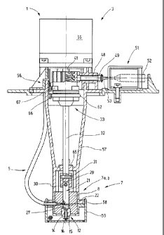
In Fig. 1, a lubricating device 1 is shown, which includes
a supply container 2, for lubricant, such as oil. A distributor
and pump unit 3 is inserted into the supply container 2 and
dispenses predetermined portions of lubricant at predetermined
_ 5 times to a group 4 of lubricant lines 5a through 51 that lead
away from it.
The pump and distributor unit 3 schematically shown in
Fig. 1 is shown separately in Fig. 2. A piston pump 7, which is
both a pump device 7a and a distributor device 7b simultaneously
is used for pumping and allocating the lubricant. The piston
pump 7, as seen particularly from Figs. 3 and 7, includes a
cylinder body 8 with a cylindrical through bore 9. The through
bore 9 is embodied on its lower end in terms of Figs. 2 and 7 as
a stepped bore, because it has one portion 10 of increased
diameter. This portion serves to receive a check valve 12,
whose valve body 14 is screwed for instance into a corresponding
thread in the portion 10.
The valve body 14 is provided with a through conduit 15
for receiving a valve closure member 16. The head of the valve
closure member 16 points toward the inner chamber, defined by
the through bore 9, of the cylinder body 8. If needed, a
spring, not shown, can brace the valve closure member against a
valve seat embodied on the valve body 14.
The valve body 14 is provided with a plurality of radial
bores 17, in the present example 12 of them (17a-171; Fig. 3),
which are all disposed in the same plane 18 to which the through
bore 9 is perpendicular. The radial bores 17a-171 are disposed
at equal angular spacings from one another, while the spacing
between the radial bore 171 and the radial bore 17a is somewhat
greater than the otherwise uniform spacings among the radial
bores 17a through 171. Check valves, not identified by '
reference numeral, are inserted into the radial bores 17 (the
8
CA 02298296 2000-02-04
reference numeral without a letter following it stands equally
for all the radial bores 17a through 171), and these check
valves allow a fluid flow in the radial direction outward, that
is, from the db 9 outward through the outlet conduit formed by
the respective radial bore 17, but not back again.
The lubricant lines 5a through 51 are connected to the
outlet valves and lead to the lubricating stations. The check
valves can be provided as needed also on an end of the
respective line 5a through 51 remote from the distributor device
7b, in which case only connection nipples are screwed into the
radial bores 17.
A piston 21 is inserted into the through bore 9, and its
outer diameter substantially matches the inside diameter of the
through bore 9, so that while the piston is seated axially
displaceably and rotatably in the through bore 9, it also
together with the through bore defines a work chamber 22
relatively tightly (Fig. 2). Along with its cylindrical jacket
face 23, the piston 21 also has a substantially plane end face
24. A control groove 25 extends over the jacket face, beginning
at the end face 24, parallel to the center axis 26 of the
piston. The length of the control groove 25 is preferably equal
to or somewhat greater than the spacing of the plane 18 from a
"top" dead center 27 of the piston; this point is represented by
a dashed line in Fig. 2.
The piston 21 reaches top dead center 27 with its end face
24 when the work chamber 22 is smallest, or in other words, in
terms of Fig. 2, when the piston 21 is in its bottommost
position.
The control groove 25, as Fig. 3 shows, is relatively
narrow and extends in the circumferential direction along the
jacket face 23 over a circumferential region that is
9
,' CA 02298296 2000-02-04
approximately equivalent to the diameter of the radial bores 17
at the wall of the through bore 9. The depth of the control
groove 25 is dimensioned such that the flow resistance in the
control groove 25 is not substantially greater than in the
radial bores 17.
On its end protruding out of the cylinder element 8, the
piston 21 is mounted in a connection cuff 29 and pinned to it
(pin 30). The connection cuff 29 is also connected via a
further pin 31 to an actuating rod 32 that leads to a drive
device 33. The actuating rod 32 is connected in a manner fixed
against relative rotation and solidly in the axial direction to
a coupling half 34, which has two ribs 35 and 36 extending
axially and disposed parallel to and spaced apart from one
another. Between these ribs, windows 37, 38 are formed, which
can be seen particularly in Fig. 6.
The coupling half 34 belongs to a coupling device 39,
whose other coupling half 40 is formed by a radial pin 42 driven
by a shaft 41. This pin with both ends engages the windows 37,
38, and after each execution of a certain rotary play, here
defined at 90°, it can come into contact with one flank of each
of the ribs 35, 36.
The shaft 41 also has a bush 43, which can be seen from
Fig. 7 and establishes the connection to the radial pin 42 and
is provided on its outside with a threaded element 44. This
threaded element has a male thread with multiple turns. Its
pitch is dimensioned such that over 90° of the circumference of
the threaded element 44, a distance is traversed in the axial
direction that corresponds to the complete piston stroke of the
piston 21.
During operation, the threaded element 44 is in
communication with a threaded element 45, which is seen in Fig.
CA 02298296 2000-02-04
and is embodied in an annular element or portion that is
supported by the ribs 35, 36 of the coupling half 34. Thus when
the rotary play of the coupling 39 is executed, the coupling
half 34 changes its axial position relative to the coupling half
5 40.
The portion of the coupling half 34 provided with the
female thread (threaded element 45) is embodied, on its outside,
as a locking wheel 46. This locking wheel has axially extending
teeth 47 of approximately trapezoidal cross section, which serve
to lock the coupling half 34 in a manner fixed against relative
rotation but axially displaceably. This can be seen from Fig.
4. A locking bar 48 is displaceably supported radially to the
locking wheel 46. the locking bar 48 is prestressed by a
compression spring 49 toward its radially outer position, in
which it is not in engagement with the locking wheel 46. A
lifting magnet 51 serves with its armature 52, via a
corresponding rod 53, to but the locking bar 48 into engagement
with the locking wheel 46, so that the rotation of the locking
wheel is blocked in discrete positions specified by the teeth
47. These blocking or locking positions each correspond to
rotary positions in which the control groove 25 (Fig. 3) is
aligned with one of the radial bores 17. Accordingly, 13
interstices between teeth are present, 12 of which correspond to
the positions of the radial bores 17, and the 13th of which
corresponds to the larger interstice between the radial bores
171 and 17a. The size of the interstices between teeth
corresponds to the size of the spacings of the radial bores 17.
The coupling half 40 is connected in a manner fixed
against relative rotation to the shaft 41, which forms the power
takeoff shaft of a stepping motor 55. This motor is oriented
coaxially to the actuating rod 32 and is supported by a
corresponding mount 56. The mount 56, which is embodied in
multiple parts, also carries the lifting magnet 51 and has a
11
CA 02298296 2000-02-04
tubular, tapering extension 57, which is disposed coaxially to
the actuating rod 32 and carries the pump unit 7 on its lower
free end. There, it has a flange-like extension 57, on which
the lubricant lines 5 can be retained and which moreover has a
_ 5 microporous sieve 59. This sieve is embodied in cup-like shape
and encloses the lower end of the extension 57. The lubricant
flowing to the inlet valve 12 must accordingly pass through the
microporous sieve 59 and is thus filtered.
On its side toward the actuating rod 32, the coupling half
34 is provided with a hub 60, which has a male thread 61. On
the hub 60, an annular, axially polarized permanent magnet 62,
shown separately in Fig. 7, is retained with the aid of a nut
63, for which nut the male thread 61 is intended. By means of
its magnetic field, the permanent magnet 62 generates a force
that keeps the threaded element 44 in engagement with the thread
45 without play. This serves to prevent an undesired idle
motion in the gear at the reversal of the rotary direction of
the stepping motor 55; the gear is formed by the threaded
element 44 and the female thread 45 and serves to convert a
rotary motion into a linear motion.
The actuating rod 32 is supported on the extension 57 in
a bush 65, which is disposed adjacent the connecting cuff 29 in
a corresponding partition of the extension 57. The bush 65
allows both a rotary and an axial motion of the actuating rod
32.
For monitoring the motion of the piston 21, a magnetic
sensor, for instance a Hall sensor 66, is disposed on the inside
of the extension 57, adjacent to the permanent magnet 62; it
detects the position of the permanent magnet 62 and
distinguishes between at least overshooting and undershooting a
switching position. If needed, a further Hall sensor or other
kind of position sensor 67 may be provided in the vicinity of
12
CA 02298296 2000-02-04
the transverse pin 42, in order to detect the position of this
pin. Both the Hall sensors as well as the stepping motor 55 and
the lifting magnet 51 are all connected to a control device,
which controls the lubricating device 1 as follows:
For describing proper operation, it will be assumed that
the piston 21 is initially in the position shown in Fig. 3, and
the locking bar 48, as a consequence of triggering of the pull
magnet 51, is in engagement with the locking wheel 46 (Fig. 4).
If the thread of the threaded element 44 is a right-handed
thread, then the stepping motor 55, at least if the transverse
pin 42 is not yet in the position represented by heavy lines in
Fig. 6, is now rotated in such a way that the transverse pin 42
is pivoted clockwise. For example, it is moved out of the
position shown in dashed lines in Fig. 6 to the position shown
in heavy lines. On traversing this course, the axially fixed
element 44 lifts the coupling half 34 in the axial direction in
such a way that the piston 21 executes one complete intake
motion. The work chamber 22 becomes larger, and lubricant, such
as oil, flows into the work chamber 22 via the inlet valve 12.
The locking wheel 46 is held in a manner fixed against
relative rotation. At the latest when the transverse pin 42
runs up against the ribs 35, 36, the stepping motor 55 stops.
The pull magnet 51 is now deexcited, and as a result the locking
wheel 46 is released. The stepping motor 55, which until now
has served to impart a reciprocating motion to the piston 21,
now positions the now freely rotatable locking wheel 46 onward
by one tooth. In the process, the transverse pin 42 carries the
ribs 35, 36 and thus the coupling half 34 along with it. The
control groove 25 is thereby moved into coincidence with the
radial bore 17a. Once this position is reached, the pull magnet
51 is triggered again and as a result presses the locking bar 48
into the corresponding interstice between teeth of the locking
wheel 46. As a result, this locking wheel is once again
13
' , , ' CA 02298296 2000-02-04
retained in a manner fixed against relative rotation.
For dispensing a desired portion of lubricant to the
lubricant line 5a, the stepping motor 55 is now triggered
counter clockwise. Because of the size of the windows 37, 28,
S the rotary motion is limited here to a one-quarter rotation. If
the stepping motor 55 traverses this course, this rotary motion
is converted, by interaction of the threaded element 44 with the
female thread 45, into an axial motion of the coupling half 34
that is oriented downward, in terms of Fig. 2. Via the
actuating rod 32, the piston 21 is moved, without rotating,
downward in the direction of its top dead center 27. The
positively displaced oil is correspondingly dispensed at the
lubricant line 5a. There is no need for the entire course
available to be traversed. The stepping motor 55 can also be
stopped before it has executed a one-quarter rotation. A lesser
quantity of oil is then correspondingly dispensed. As a result,
fine metering of the oil portions to be dispensed is attainable.
Once the downward motion of the piston 21 has ended, the
stepping motor 55 is actuated clockwise again, until the
transverse pin 42 again meets the ribs 35, 36. The pull magnet
51 is now released, and as a result the compression spring 49
moves the locking bar 48 radially outward and releases the
locking wheel 46. The stepping motor can now rotate onward by
one tooth (or as needed a plurality of teeth), carrying the
coupling half 34 and thus the piston 21 by rotation along with
it, in order to approach the next lubricating position. For
instance, the control groove 25 is now made to coincide with the
radial bore 17b. The process described in conjunction with the
radial bore 17a now begins over again. As described, all the
radial bores 17 can thus be approached in succession, and thus
all the lubricant lines 5 can be supplied separately with
suitable portions of oil. '
14
CA 02298296 2000-02-04
The dispensing of an oil portion can be done in pulsed
fashion, as illustrated by Fig. 8; the injection pressure p
built up by the pump device 7a is modulated within a lubricating
interval tl t2. To that end, the stepping motor 55 is triggered
. 5 and moved incrementally, so that the piston 21 is likewise moved
incrementally. In each of the brief resting periods, the
pressure p can drop somewhat below a pressure limit value pl.
The connected nozzles begin to inject at the pressure limit
value pl. If the pressure meanwhile drops below this value, for
instance to a somewhat lesser value po, then the nozzles inject
intermittently. The incoming flow vl to the nozzles fluctuates
as a result and over time, as a consequence of the elasticity of
the lines. The nozzles inject the oil stream v2 droplet by
droplet in the form of micropulses, so that the oil stream
between individual droplets, because of the brief pressure
drops, is zero. In this way, even small oil quantities can be
dispensed over a prolonged time in the injection stream, using
relatively large nozzles that are not likely to become stopped
up.
When the lubricating device 1 is put into operation,
venting of the pump device 7a may initially be needed. To that
end, the piston 21 is rotated into a venting position, in which
its control groove 25 coincides with a radial bore 171 that is
open to the outside and in which no check valve is disposed.
One or more complete piston strokes now cause the expulsion of
air and the filling of the pump volume with oil. Proper
operation can then be begun.
A modified embodiment of the locking mechanism is shown in
Fig. 8. Here the locking wheel 46 is embodied as a ratchet
wheel. The locking bar 48 is embodied as a pawl. This makes it
unnecessary to trigger the pull magnet each time the locking
wheel 46 is to be indexed onward. The locking bar 48 is spring-
loaded toward the locking wheel 46. It enables a rotation of
. , " ~ CA 02298296 2000-02-04
the ratchet wheel 46 in the clockwise direction (arrow 70) for
rotating the piston 21 and thus actuating the distributor. In
the opposite direction (arrow 71), however, any rotation is
blocked, so that the pumping operation can be performed. It is
now necessary to actuate the lifting magnet 51 only in a very
few exceptional cases.
A further modified embodiment is shown in Fig. 10. The
toothing of the locking wheel 46 has teeth 47 with a relatively
slight flank pitch. The locking bar 48 is embodied as a
radially resilient pawl. The control of the rotary motion of
the piston 21 in this embodiment is effected in that the
stepping motor 55, once the play of the coupling device 39 has
been traversed, overcomes the detent moment of the locking bar
by rotating clockwise or counterclockwise.
In a lubricating device for a plurality of lubricating
stations, especially for supplying lubricant to knitting
machines, a pump device 7a is provided that acts at the same
time as distributor device 7b. To that end, the pump and
distributor unit 7 has a piston 25, which is provided with a
control groove 25. The corresponding pump cylinder has one
inlet and a plurality of outlets that are distributed over the
cylinder wall. Depending on which of the outlets the control
groove 25 of the piston 21 is made to coincide with, a
corresponding lubricating station is selected. The pump device
7 is thus at the same time a distributor device.
16