Note: Descriptions are shown in the official language in which they were submitted.
CA 02298524 2000-O1-28
WO 99/06167 PGT/EP98/04932
-1-
METAL POWDER COMPRESSION TOOL
The present invention relates generally to the manufacture of articles by
sintering
techniques and more specifically to a powder compression tool for forming a
work piece
herein termed a compact, which is then placed in a sintering furnace.
In general terms, sintering consists of compressing metal powder, generally a
steel
powder, to obtain a compact of definitive shape. This compact, whose shape is
maintained only by cohesion of the powder, is then passed through a furnace at
a
sintering temperature below the melting temperature, but sufficient for the
powder partiGes
to join.
After sintering, the product will typically exhibit a final density which
approaches, but does
not equal the density of the metal in question. In the case of steel powder,
it is possible to
achieve final densities on the order of 7.4 - 7.5 g/cc, using the conventional
pressing and
sintering techniques described below, whereas the density of steel itself is
on the order of
7.8 - 7.9. For ease of reference, this will be referred to as the maximum
density.
It is an object of the present invention to provide a modii:led pressing
process and
apparatus capable of operation to yield sintered products having a final
sintered density
which more nearly approaches the maximum density of the material, and in the
case of
steel, a final sintered density of over 7.5. According to the present
invention, this is
achieved by a single press, single sinter process in which a metal powder mix
containing
from about 0.3 to 0.5 weight % of a solid lubricant is pressed in a single
step in a die
having a working clearance of at least 45 pm under a pressure of at least 800
MPa to form
a compact for subsequent sintering.
CA 02298524 2000-O1-28
WO 99/06167 PCT/EP98/04932
-2-
For better understanding of the basic technology, conventional powder
compression
processes will now be described with the aid of Figures 1A, 1 B and 1C.
Figures 1A to 1C illustrate the operation of a powder compression tool. The
tool includes a
die 10 with a cavity 12 arranged through it. This cavity 12 defines the shape
or profile of
the desired compact, including features such as a smooth surface, an
indentation, or other
characteristic. Die 10 co-operates with an upper punch 14 and a lower punch 15
which
penetrate through both ends of the cavity 12.
In Figure 1A, the cavity 12 is filled with metal powder flush with the upper
surface of
die 10. Lower punch 15 is at a specific position determined by the volume of
powder
required to obtain the desired height and density of the final product. Once
cavity 12 is
filled with powder, upper punch 14 is lowered.
In Figure 1 B, upper punch 14 reaches an end position determined by the
pressure applied
to both punches. A compact 17 of desired shape is then obtained in cavity 12,
formed of
powder particles sufficiently cohered together to allow it to be handled and
carried to a
sintering furnace (not shown).
In Figure 1C, upper punch 14 is withdrawn while lower punch 15 is raised to
eject
compact 17 from the cavity 12. The compact is then carried to the sintering
furnace. To
eject compact 17, instead of raising the punch 15, die 10 could be lowered. It
will be
appreciated that various options are possible.
As illustrated in Figures 1A and 1B, the volume of the powder decreases
considerably on
application of pressure. For conventional pressures, on the order of 700 MPa,
the volume
decreases by a factor 2.3 to 2.5. This decrease in volume is accompanied by
rubbing of
the powder against the walls of the cavity 12 over the length of travel of the
punch. It is
thus essential to lubricate the walls of the cavity 12 to minimise friction.
Lubrication of the walls of the cavity 12 being impractical in production, it
is preferred to
include the lubricant in the metal powder. For the powder to be able to
properly flow to fill
up the cavity, the lubricant also comes as a powder.
Of course, lubrication also facilitates ejection of the compact 17, without
damage.
CA 02298524 2000-O1-28
WO 99/06167 PCT/EP98/04932
-3-
The proportion of lubricant commonly used in the metal powder is from 0.6 to
0.8% in
weight. However, the lubricant is about eight times less dense that the metal
powder, and
occupies an incompressible volume which cannot be replaced by metal during the
compression. As a result, especially upon elimination of the lubricant while
sintering, the
obtained compacts are porous and have a mechanical strength which is
substantially
lower than that of pure metal.
Thus in practical terms, conventional pressing and sintering processes can
yield products
with a final density (in the case of steel) of up to 7.5. More typically,
using a pressure of
700 MPa and 0.8% lubricant, the final density is only around 7.15. In theory,
higher
pressures would tend to increase the final density, but in practice, pressures
exceeding
about 800 MPa have been observed to result in rapid tool damage, even though
the tool
itself is, in isolation, capable of withstanding more than 2000 MPa.
It is appropriate to mention that final sintered density is much more
significant than the so-
called "theoretical maximum density" of the compact, including lubricant,
before sintering.
Reducing the lubricant quantity may make it possible to achieve a higher
percentage of
the maximum theoretical density of a particular metal powderllubricant
mixture, but even
values such as 96% of maximum theoretical density correspond only to a final
sintered
density of 7.15 in the case of steel powder containing 0.8% lubricant.
A final density, in the case of steel powder, of around 7.15 thus is typical
of that obtained
through a conventional single pressJsingle sinter process, in which a single
powder
compression step is performed, at about 700 MPa, followed by sintering to
obtain the final
product.
To obtain sintered compacts with higher densities, a double press/double
sinter process
can be used, in which, after compression under the above-mentioned conditions,
the
compact undergoes a pre-sintering treatment to vaporise the lubricant, so as
to empty the
pores that it occupies. The compact is then submitted, before a final
sintering, to a second
compression during which the material, not yet generally integral, tends,
through plastic
deformation, to occupy the empty pores. With such a process, however, final
densities
above 7.5 cannot be achieved. Further, such a two-stage process is more
expensive to
implement than a single press/single sinter process.
CA 02298524 2000-O1-28
WO 99/06167 PCT/EP98/04932
-4-
There is also a warm forming process in which the die and powder are heated to
about
100-150°C to liquefy the lubricant which then escapes by draining from
the pores. The
maximum densities obtained are on the order of 7.4 (in the case of steel) and
the process
is also expensive to implement.
A further object of the present invention is to provide a compression tool
which can more
successfully withstand operation at higher than normal pressures.
Yet another object of the present invention is to provide such a tool which
enable
compacts of particularly high final density to be obtained through a single
pressing
process.
In conventional compression tools, the clearance between punches and dies has
always
been made as small as possible. This is to avoid or at least minimise
extrusion of powder
through the clearance, as well as the formation of moulding flash, generally
referred to as
"beards". The clearance commonly found in typical tools ranges from 10 to
20Nm.
Figure 2 illustrates on an enlarged scale the clearance in the tool and the
deformation
which take place during a compression operation. The nominal diameters of
moving
punch 14 and of cavity 12 of the die are indicated in dotted lines. During
compression,
punch 14 tends to undergo barrel deformation. At a certain pressure level, the
punch
comes into contact with the die along its entire circumference while still
moving. The
resulting friction increases as punch 14 comes closer to its final position
and the
deformation also increases.
If the friction were uniform over the punch circumference, the tool would be
able to better
withstand high pressure. However, in practice, punch 14 always rubs more
against one
side than against the other, which causes a high bending stress in the punch
and even in
the die. The compression tool, which is designed primarily for hardness,
poorly withstands
bending stress and prematurely deteriorates if the pressure exceeds 800 MPa.
Of course, the friction of punch 14 against die 10 may also damage the surface
finish of
the cavity 12, making the subsequent ejection of the compact 17 more difficult
and
affecting in tum its surface finish and that of components subsequently
pressed in the die.
CA 02298524 2000-O1-28
WO 99/06167 PCT/EP98/04932
-5-
As shown in Figure 2, the compact 17 itself also tends to undergo barrel
deformation
when under compression, pushing against the side walls of the cavity 12. When
the punch
is withdrawn, the compact 17 and the walls of cavity 12 may, if excessive
force has been
applied, undergo permanent deformation, making the ejection of the compact
more
difficult. This ejection is normally facilitated by the presence of a
sufficient amount of
lubricant, of course.
To avoid or at least minimise the above-mentioned problems, the present
invention
provides an increased clearance between the elements of the tool, especially
between the
moving punch and the die, so that this clearance is not affected by any
deformation of the
elements during the compression operation. The presence of a clearance may
tend to
accentuate the generation of beards on the edges of the produced compacts, but
such
beards only affects, for the most part the aesthetic appearance of the
compacts. The
increased clearance is preferably not greater than the mean grain size of the
powder, or
else the powder grains will tend to jam together in the gap, thereby
increasing friction as
well as causing excessive loss of powder, in an extreme case.
The article by G Bockstiegel et al: 'The influence of lubrication, die
material and tool
design upon die wear in the compacting of iron powders", Modem Developments in
Powder Metallurgy, Proceedings of the 1970 International Powder Metallurgy
Conference,
vol. 4, 1971, New York, London, describes experiments made with punchldie
clearances
of 5, 10, 25 and 45 Nm, and concludes that the use of large clearances is
detrimental in
terms of tool wear.
In contrast, the present invention uses large clearances, in particular
greater than 45 Nm.
According to one embodiment of the present invention, the elements of the tool
are
arranged to form a compact having one face flush with a surface of the die.
According to another embodiment of the present invention, the tool includes a
second
punch (15, 14) co-operating with the cavity (12) from the side opposite to the
point of entry
of the first punch, the second punch, during compression, being arranged to
seal the
cavity at or in the vicinity of the die surface, the first punch being used to
eject the
compact at the end of compression.
CA 02298524 2000-O1-28
WO 99/06167 PCT/EP98/04932
-6-
According to another embodiment of the present invention, the >arst punch (15)
includes
axially protruding edge portions which serve to form recessed edge regions on
the
compact these edge regions serving to accommodate to a significant extent any
beards
formed.
According to a further embodiment of the present invention, the walls of the
cavity are
coated with a material having a low friction coefficient relative to the
powder and which is
able to withstand repeated use.
According to a preferred embodiment of the present invention, the coating is
of a
diamond-like carbon material.
According to a preferred embodiment of the present invention, less than 0.5,
or more
preferably, less than 0.4 weight % of lubricant is included in the powder to
be moulded into
a compact.
According to a particularly preferred embodiment of the present invention, the
powder
includes about 0.3% weight of lubricant when the die cavity walls are coated
as mentioned
above.
It is preferred that the green density of the compact prior to sintering is at
least 7.4 g/cc,
It has been found that the present invention can in the case of steel powder,
achieve, by a
cold, single pressing/sintering of a mixture of metal powders and
significantly reduced
amount of lubricant, a final density of at least 7.5.
In order than the invention be better understood, particularly preferred
embodiments of it
will now be described, by way of example only, with reference to the
accompanying
Figures, which are as follows:-
Figures 1A to 1C, (previously described) show a conventional tool for metal
powder
compression, at three steps of a compression process;
Figure 2, (also previously described) illustrates on an enlarged scale the
deformations of
the tool during a compression operation;
CA 02298524 2000-O1-28
WO 99/06167 PCT/EP98/04932
_7_
Figure 3 further illustrates on an enlarged scale the deformation of a tool
according to the
present invention during a compression operation;
Figures 4A and 4B show a tool according to the present invention at two stages
of a
compression operation; and
Figure 5 shows an enlarged view of one edge of a compact obtained using the
tool of
Figures 4A and 4B.
In the interests of clarity the relative deformations have been exaggerated to
make them
more visible. In practice they are very small but significant.
In Figure 3, the nominal shapes of punch 14 and of stamp 12 are illustrated by
dotted
lines. According to the present invention, the dimensions of the tool are
chosen so that the
clearance between moving punch 14 and die 10 is relatively large with respect
to ttte
clearance of a conventional tool illustrated in Figure 2. More specifically,
as illustrated,
this clearance is greater than the maximum radial expansion reached by punch
14 at the
desired maximum compression pressure. However, this clearance is selected to
be not
greater than a limit at which the powder escapes from the die, This limit
reaches 100 Nm
for commonly used metal powders, and it is greater than the mean grain size of
the
powder, because the grains tend to jam together in the clearance, as mentioned
earlier.
In practice, the clearance is chosen according to the diameter of the compact.
For
example, good results are obtained by choosing a clearance of 50 Nm for
diameters
reaching 50mm, a Gearance of 60 Nm for diameters between 50 and 80mm, and a
clearance of 80 Nm for clearances above 80mm.
By choosing such a clearance, the punch and die will undergo much less
distortion as
compared to the conventional tool of Figure 2 and will successfully operate at
higher
pressures. A tool according to the present invention has been successfully
tested at more
than 1050 MPa. Further, since the contact areas are of smaller extent and the
effects of
friction are lower, the wall of cavity 12 maintains an acceptable surface
finish for a longer
period of time in service.
CA 02298524 2000-O1-28
WO 99/06167 PCT/EP98/04932
.$_
Preferably, the largest practicable clearance is chosen for all the tool
elements. Indeed,
these elements are generally designed to be movable one with respect to
another during
use so as to promote homogenisation within the compact. Further, assembly of
the tool is
thus facilitated by having the largest practicable clearance.
It will be noted that the existence of the preferred relatively large
clearance between
punch and die inevitably causes the forming of beards. One might expect that
the beard
produced by a tool according to the present invention would be bigger, and
thus more
unacceptable, than that produced by conventional low or tight clearance tools.
In fact, the
beard produced by a tool according to the present invention is wider than that
produced by
a conventional tool, but it is not taller. 1t is mostly the height of beards
which in
unacceptable. The beards obtained on the compacts produced by means of a tool
according to the present invention may be removed or otherwise processed
conventionally.
If a tool according to the present invention is used under above normal
pressure, in the
way described in relation with Figures 1A to 1C, compact 17 will exhibit
greater barrel
deformation than in a conventional case. As a result, compact 17 would be more
difficult
to eject and more lubricant would accordingly be required, which militates
directly against
the desired increase in density.
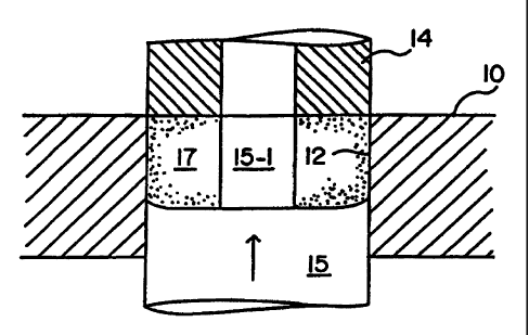
Figures 4A and 4B illustrate a particularly prefer-ed form of tool according
to the present
invention, minimising this problem. The moving punch is in this case the lower
punch 15
which is provided with an upwardly extending broach portion 15-1. This co-
operates with a
corresponding recess in the upper punch 14 to make a recess or opening in a
compact 17
to be compressed.
In Figure 4A, lower punch 15 is, as in Figure 1A, set at a specific position
which
determines the volume of powder contained by cavity 12. This cavity 12 is
filled flush with
the upper surface of die 10. Then, upper punch 14 is lowered to seal the
cavity 12, if
necessary by slightly penetrating into the latter. The compression operation
is then
performed at the top of the die by appropriately combining relative motions of
the punches
and of the die.
CA 02298524 2006-05-08
WO 99/0667 PCT/EP98/04932
_g_
In Figure 4B, punch 15 has reached its final position, as determined by the
pressure
applied to it.
As previously, the compression of compact 17 generates radial force vrrhich
deform die 10.
However, since compact_17 is then positioned towards one face of the die, the
wails of
cavity 12 do not deform as a barrel but, as illustrated, as an upwardly
opening cone. This
conical shape is partially retained when punch 14 is raised, which
considerably helps the
ejection of compact 17 by Power punch 95.
Using the concepts of this invention, the proportion of lubricant may be
smaller than 0.5
weight %. The combination of this reduction in the proportion of lubricant and
of the
increase in the compression pressure, up to approximately 1050 MPa, produced
final
product densities in excess of 7.5 (based on steel powder).
Even less lubricant, about 0.3 weight %, may be used when the walls of the die
cavity 12
are coated with a material having a low. friction coefficient with the powder.
This material
should, as previously mentioned, withstand repeated forces ca~rsed by
successive
compression operations. A material which meets these requirements is DLC
(Diarnond
Like Carbon). ~'
The punch edges, as is shown in Figures 4A and 4B for lower punch 15,
preferably slightly
protrude axially because this has been found to attenuate beard formation.
Figure 5 shows an enlarged and deliberately exaggerated view of an edge of
compact 17
obtained with such an arrangement: The edge of compact 17 is indented with
respect to
the lower surface, so that beard 17-1 resulting from the clearance is entirely
included
within this indentation. Thus, beard 17-1 does not affect the technical
function of the
corresponding surtace of the compact, if this surface is not subsequently
machined.
Various alterations and modi#ications of the present invention will readily
occur to those
skilled in the art. For example, it is not required to compress a compact
right at or closely
adjacent one surface of the die cavity, as shown in Figures 4A and 4B, if this
compact
already has a tapered shape facilitating its ejection. The compact may then be
formed at
the middle of the die cavity, as shown in Figure 1B, while applying the higher
pressures
useable according to the present invention, with a reduced amount of
Lubricant.