Language selection

Search

Patent 2298678 Summary

Third-party information liability

Some of the information on this Web page has been provided by external sources. The Government of Canada is not responsible for the accuracy, reliability or currency of the information supplied by external sources. Users wishing to rely upon this information should consult directly with the source of the information. Content provided by external sources is not subject to official languages, privacy and accessibility requirements.

Claims and Abstract availability

Any discrepancies in the text and image of the Claims and Abstract are due to differing posting times. Text of the Claims and Abstract are posted:

  • At the time the application is open to public inspection;
  • At the time of issue of the patent (grant).
(12) Patent: (11) CA 2298678
(54) English Title: VENTILATION VALVE FOR A MOLD IN PRODUCING INSULATORS
(54) French Title: SOUPAPE DE VENTILATION POUR UN MOULE DANS LA FABRICATION D'ISOLANTS
Status: Term Expired - Post Grant Beyond Limit
Bibliographic Data
(51) International Patent Classification (IPC):
  • H01B 19/00 (2006.01)
(72) Inventors :
  • JEUTHNER, HERMANN (Germany)
  • LEICHT, ALFONS (Germany)
  • WELZ, JOHANN GEORG (Germany)
(73) Owners :
  • HAEFELY TRENCH MWB GMBH
  • TRENCH GERMANY GMBH
(71) Applicants :
  • HAEFELY TRENCH MWB GMBH (Germany)
  • TRENCH GERMANY GMBH (Germany)
(74) Agent: MARKS & CLERK
(74) Associate agent:
(45) Issued: 2005-10-25
(86) PCT Filing Date: 1998-07-29
(87) Open to Public Inspection: 1999-02-18
Examination requested: 2003-07-09
Availability of licence: N/A
Dedicated to the Public: N/A
(25) Language of filing: English

Patent Cooperation Treaty (PCT): Yes
(86) PCT Filing Number: PCT/DE1998/002210
(87) International Publication Number: WO 1999008291
(85) National Entry: 2000-01-31

(30) Application Priority Data:
Application No. Country/Territory Date
297 14 181.3 (Germany) 1997-08-08

Abstracts

English Abstract


The aim of the invention is to provide an improved
ventilation valve, especially for ventilating a mould in the
production of umbrella type insulators, so that harmful
deformation of the moulded body can be avoided during removal
from the mould. This is achieved by providing the
ventilation valve with a rod-like or pin-shaped housing with
an orifice on one of its front faces and by providing a valve
body on the other front face which is detachably mounted in
an axial extension of the valve housing.


French Abstract

L'invention vise à perfectionner une soupape de ventilation (8), notamment pour ventiler un moule (5) destiné à la fabrication d'isolateurs type parapluie (1), de manière à éviter une déformation préjudiciable du corps moulé lors de l'extraction du moule (5). A cet effet, la soupape de ventilation (8) est constituée d'un carter (8.2) en forme d'aiguille, sur une face frontale duquel un orifice de soupape (8.5) est disposé et sur une autre face frontale duquel un corps de soupape (8.3) est monté amovible dans le prolongement axial du carter de soupape (8.2).

Claims

Note: Claims are shown in the official language in which they were submitted.

The embodiments of the invention in which an exclusive
property or privilege is claimed are defined as follows:
1. A valve to ventilate a mold for producing umbrella-
shaped insulators, the valve comprising:
a pin-shaped valve housing;
a valve orifice on a front face of the valve housing;
a valve body detachably mounted on a back face as an
axial extension of the valve housing, the valve body having
a bore extending coaxially to an axially extending
cylindrical valve space in the valve housing;
a connecting rod extending through the bore and through
the valve space to the valve orifice;
a valve piston positioned at one end of the connecting
rod and having a seal positioned on the front face of the
valve piston to engage and tightly close the valve orifice;
at least one axial overflow duct in the piston;
the valve piston having a diameter corresponding to an
inside diameter of the valve housing adjacent the valve
orifice;
a pressure spring between a pressure surface of the valve
body and a back side of the valve piston, and
the valve housing having an air inlet opening which
extends into the valve space.
2. The ventilation valve according to claim 1, further
comprising a stop flange on the connecting rod and
8

positioned at least partially within the valve space;
wherein, the pressure spring biases the piston toward the
orifice by engaging the stop flange.
3. ~The ventilation valve according to claim 1, wherein
the pressure spring biases the piston toward the orifice by
engaging the back side of the valve piston.
4. ~The ventilation valve according to any one of claims 1
to 3, wherein the seal is a flat, disk-shaped seal.
5. ~The ventilation valve according to any one of claims 1
to 4, wherein the seal is provided with at least one axial
overflow duct.
6. ~The ventilation valve according to any one of claims 1
to 5, wherein the inside diameter of the housing extending
from the valve orifice is constant over a path of travel of
the valve piston.
7. ~The ventilation valve according to any one of claims 1
to 6, wherein another end of the connecting rod projects
beyond the valve body.
8. ~The ventilation valve according to claim 7 wherein the
seal is provided with at least one axial overflow duct.
9

9. The ventilation valve according to any one of claims 1
to 8, wherein the valve body is screwed into the valve
housing.
10. The ventilation valve according to claim 9, wherein
the seal is provided with at least one axial overflow duct.
11. The ventilation valve according to claim 9 wherein
another end of the connecting rod projects beyond the valve
body.
12. The ventilation valve according to claim 11 wherein
the seal is provided with at least one axial overflow duct.

Description

Note: Descriptions are shown in the official language in which they were submitted.


CA 02298678 2005-05-04
VENTILATION VALVE FOR A MOLD IN PRODUCING INSULATORS
The present invention relates to a ventilation valve,
particularly for ventilating a mold for producing umbrella-type
insulators as described herein.
In the production of umbrella-type insulators, which consist
of a core constructed as a solid or hollow body and several
umbrellas which are molded to it and have downward extending
collars provided thereon and connected with the core, the
substantially funnel-shaped mold is filled with an elastomer,
preferably made of silicone. The solidified body is then removed
from the mold (German Patent Document DE-A-2618653_ In the
process, a vacuum is initially formed between the mold and the
umbrella which first deforms the umbrella until air can flow into
the mold at one point. During the. removal from the mold,
tensions and even cracks occur in the umbrella which make the
umbrella unsuitable for a use as an insulator.
It is an object of the present invention to avoid the
damaging deformation of molded bodies of any type during the
removal from the mold by using a new type of ventilation valve.
1

CA 02298678 2005-O1-04
According to an aspect of the present invention there
is provided a valve to ventilate a mold for producing
umbrella-shaped insulators, the valve comprising a pin-
shaped valve housing, a valve orifice on a front face of
the valve housing, a valve body detachably mounted on a
back face as an axial extension of the valve housing, the
valve body having a bore extending coaxially to an axially
extending cylindrical valve space in the valve housing, a
connecting rod extending through the bore and through the
valve space to the valve orifice, a valve piston positioned
at one end of the connecting rod and having a seal
positioned on the front face of the valve piston to engage
and tightly close the valve orifice, at least one axial
overflow duct in the piston, the valve piston having a
diameter corresponding to an inside diameter of the valve
housing adjacent the valve orifice, a pressure spring
between a pressure surface of the valve body and a back
side of the valve piston, and the valve housing having an
air inlet opening which extends into the valve space.
2

CA 02298678 2005-O1-04
The ventilation valve according to the invention can be
cleaned in a fast and simple manner because the valve body can
easily be demounted from the valve housing and can therefore be
cleaned outside a mold or the like. The ventilation valve
according to the invention can also be used for other ventilation
measures, particularly for other removal processes from a mold,
in the case of which a vacuum will or may form_
Additional advantageous details of the invention are
indicated in the subclaims and will be explained in detail in the
following by means of an embodiment illustrated in the drawing.
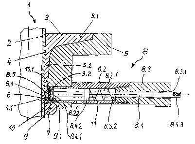
Figure 1 is one half of a lateral view in the cross-section
of an umbrella molded to a hollow core, together with the mold
and the ventilation valve according to the invention in the cast
condition of the umbrella;
Figure 2 is a view of a section of the ventilation valve
with the valve seat; and
Figure 3 is a view of the valve seat according to the
2a

CA 02298678 2000-O1-31
intersection I-I of Figure 2.
Reference number 1 indicates a part of an umbrella-type
insulator which has a core 2 or a core wall constructed as a
hollow body and an umbrella 3 molded thereto which has a molded-
on collar 4. The core 2 consists of an insulating material,
preferably silicone, which is reinforced by means of reinforcing
materials, particularly glass fibers. A one-piece or multi-piece
mold 5 is pushed over the core 2, which mold 5 has a funnel-
shaped mold space 5.1 shaped corresponding to the umbrella 3 with
the collar 4 to be molded. The portion 5.2 of the mold space 5.1
forming the collar 4 has a ring gap 6 at the collar end 4.1,
which ring gap 6 is closed off for the casting process by an
elastic seal 7, such as a ring seal or O-seal.
In the area of the collar end 4.1, a rod-like or pin-shaped
ventilation valve 8 is provided laterally in the mold 5, for
example, in the form of a disk valve or cone valve. The
ventilation valve 8 can be screwed into the mold 5 or may, for
example, by tightly inserted and fastened by means of a stud
screw or the like. The outer surface 8.1 of the ventilation
valve 8 advantageously extends to the surface of the umbrella 3
or to the surface 4.2 of the collar 4 of_ the umbrella 3. In
particular, it is flush with the surface of the mold 5.
3

CA 02298678 2000-O1-31
For producing an umbrella 3 with a collar 4, the mold 5 is
first placed at the assigned location on the core 2 or on the
core wall and is sealed off by means of the elastic seal 7.
Subsequently, the mold space 5.1 is filled from above with a
casting material which will then solidify to form an insulating
body. A suitable material is an unreinforced or reinforced
polymeric material, such as silicone, which is at first pourable
and then solidifies as the result of cross-linkage. During the
cross-linkage, this material bonds with the material of the core
2 or of the core wall. After the hardening or solidifying of the
cast-in material, the mold 5, together with the seal 7, is moved
downward in the drawing. In the resulting hollow space, a vacuum
is now formed which, in the absence of the valve 8, pulls the
umbrella 3 downward, particularly at the outer edge, whereby
tensions or even cracks may be formed on its top side.
According to the invention, the ventilation valve 8 is
constructed as a valve which, in the inoperative position, is in
the closed position. It consists of a rod-type or pin-shaped
valve housing 8.2 and of a valve body 8.3 which is screwed onto
this valve housing 8.2 in an axial extension or can be screwed
into this valve housing 8.2. In a preferably central bore 8.3.1,
which is coaxial to the valve space 8.2.1 of the valve housing
8.1, a connecting rod 8.4 is guided in a displaceable manner.
4

CA 02298678 2000-O1-31
The connecting rod 8.4 extends through the valve space
8.2.1. At the end 8.4.1 of the connecting rod 8.4, a valve
piston 9 is provided which has a seal 10. In the inoperative
position of the ventilation valve 8" the seal rests sealingly
against an orifice 8.5 of the outer surface 8.1 of the valve
housing 8.2, in that it is held in the closed position by way of
a pressure spring 11. For this purpose, the pressure spring 11
is clamped between a pressure surface 8.3.2 of the valve body 8.3
and a stop flange 8.4.2 provided in the area of the valve space
8.2.1 on the connecting rod 8.4, or is clamped on the rear side
9.1 of the valve piston 9.
By pulling on the end 8.4.3 protruding from the valve body
8.3, the connecting rod 8.4 can be pulled to the outside against
the force of the pressure spring 11; the seal 10 can be lifted
off the valve orifice 8.5; and the ventilation valve 8 can thus
be opened.
The valve housing 8.2 has an air inlet opening 8.2.2, by way
of which, when the ventilation valve 8 is open, air or another
gaseous medium can flow into the valve space 8.2.1 and can flow
out by way of the valve orifice 8.5. For a better air flow-
through, the valve piston 9 is preferably provided with lateral
overflow ducts 9.2 and optionally also the seal 10 is provided

CA 02298678 2000-O1-31
with correspondingly arranged lateral overflow ducts 10.1.
In the case of the illustrated system, the method of
operation of the ventilation valve 8 according to the invention
is as follows:
The initially described casting material is poured into the
mold 5. After the solidification of the casting material, the
mold 5, together with the elastic seal 7, is pushed downward in
the drawing. Simultaneously - or preferably, shortly before -,
the ventilation valve 8 is opened up and the mold 5 is ventilated
thereby, so that the cast umbrella 3 can easily and without any
damage be removed from the mold S.
An important advantage of the new ventilation valve 8
consists of the fact that the valve housing 8.2 can be placed in
the mold 5 and can be fastened in the mold 5, for example, by way
of a stud screw, while, on the other hand, the valve body 8.3
with the connecting rod 8.4, the pressure spring 11, the valve
piston 9 and the seal 10 can easily be detached from and taken
out of the valve housing 8.2. These removed parts can then be
cleaned outside the mold 5, if, for example, the overflow ducts
9.2 and/or 10.1 are clogged with the cast resin, particularly
silicone. Individual parts may also easily be replaced. The
6

CA 02298678 2000-O1-31
valve housing 8.2 therefore remains fixedly connected with the
mold 5. The cleaning and a possibly required replacement of
parts can therefore take place more rapidly and more conveniently
than in the case of a ventilation valve which forms a unit which
cannot be separated.
7

Representative Drawing
A single figure which represents the drawing illustrating the invention.
Administrative Status

2024-08-01:As part of the Next Generation Patents (NGP) transition, the Canadian Patents Database (CPD) now contains a more detailed Event History, which replicates the Event Log of our new back-office solution.

Please note that "Inactive:" events refers to events no longer in use in our new back-office solution.

For a clearer understanding of the status of the application/patent presented on this page, the site Disclaimer , as well as the definitions for Patent , Event History , Maintenance Fee  and Payment History  should be consulted.

Event History

Description Date
Inactive: Expired (new Act pat) 2018-07-29
Grant by Issuance 2005-10-25
Inactive: Cover page published 2005-10-24
Inactive: Final fee received 2005-08-10
Pre-grant 2005-08-10
Letter Sent 2005-06-17
Notice of Allowance is Issued 2005-06-17
Inactive: Approved for allowance (AFA) 2005-05-27
Amendment Received - Voluntary Amendment 2005-05-04
Inactive: S.30(2) Rules - Examiner requisition 2005-01-28
Amendment Received - Voluntary Amendment 2005-01-04
Letter Sent 2003-08-18
Request for Examination Requirements Determined Compliant 2003-07-09
Request for Examination Received 2003-07-09
Amendment Received - Voluntary Amendment 2003-07-09
All Requirements for Examination Determined Compliant 2003-07-09
Letter Sent 2000-11-09
Inactive: Single transfer 2000-10-12
Inactive: Multiple transfers 2000-10-12
Inactive: Cover page published 2000-03-29
Inactive: First IPC assigned 2000-03-28
Inactive: Courtesy letter - Evidence 2000-03-21
Inactive: Notice - National entry - No RFE 2000-03-14
Application Received - PCT 2000-03-13
Application Published (Open to Public Inspection) 1999-02-18

Abandonment History

There is no abandonment history.

Maintenance Fee

The last payment was received on 2005-05-04

Note : If the full payment has not been received on or before the date indicated, a further fee may be required which may be one of the following

  • the reinstatement fee;
  • the late payment fee; or
  • additional fee to reverse deemed expiry.

Please refer to the CIPO Patent Fees web page to see all current fee amounts.

Owners on Record

Note: Records showing the ownership history in alphabetical order.

Current Owners on Record
HAEFELY TRENCH MWB GMBH
TRENCH GERMANY GMBH
Past Owners on Record
ALFONS LEICHT
HERMANN JEUTHNER
JOHANN GEORG WELZ
Past Owners that do not appear in the "Owners on Record" listing will appear in other documentation within the application.
Documents

To view selected files, please enter reCAPTCHA code :


To view images, click a link in the Document Description column. To download the documents, select one or more checkboxes in the first column and then click the "Download Selected in PDF format (Zip Archive)" or the "Download Selected as Single PDF" button.

List of published and non-published patent-specific documents on the CPD .

If you have any difficulty accessing content, you can call the Client Service Centre at 1-866-997-1936 or send them an e-mail at CIPO Client Service Centre.


Document
Description 
Date
(yyyy-mm-dd) 
Number of pages   Size of Image (KB) 
Description 2000-01-31 7 203
Abstract 2000-01-31 1 17
Drawings 2000-01-31 1 35
Claims 2000-01-31 3 61
Cover Page 2000-03-29 1 48
Claims 2005-01-04 3 69
Description 2005-01-04 8 225
Description 2005-05-04 8 227
Representative drawing 2005-06-10 1 18
Abstract 2005-06-16 1 17
Cover Page 2005-10-05 1 48
Notice of National Entry 2000-03-14 1 193
Courtesy - Certificate of registration (related document(s)) 2000-11-09 1 113
Reminder - Request for Examination 2003-04-01 1 120
Acknowledgement of Request for Examination 2003-08-18 1 173
Commissioner's Notice - Application Found Allowable 2005-06-17 1 160
Correspondence 2000-03-14 1 14
PCT 2000-01-31 10 404
Correspondence 2005-08-10 1 31