Sélection de la langue

Search

Sommaire du brevet 2298678 

Énoncé de désistement de responsabilité concernant l'information provenant de tiers

Une partie des informations de ce site Web a été fournie par des sources externes. Le gouvernement du Canada n'assume aucune responsabilité concernant la précision, l'actualité ou la fiabilité des informations fournies par les sources externes. Les utilisateurs qui désirent employer cette information devraient consulter directement la source des informations. Le contenu fourni par les sources externes n'est pas assujetti aux exigences sur les langues officielles, la protection des renseignements personnels et l'accessibilité.

Disponibilité de l'Abrégé et des Revendications

L'apparition de différences dans le texte et l'image des Revendications et de l'Abrégé dépend du moment auquel le document est publié. Les textes des Revendications et de l'Abrégé sont affichés :

  • lorsque la demande peut être examinée par le public;
  • lorsque le brevet est émis (délivrance).
(12) Brevet: (11) CA 2298678
(54) Titre français: SOUPAPE DE VENTILATION POUR UN MOULE DANS LA FABRICATION D'ISOLANTS
(54) Titre anglais: VENTILATION VALVE FOR A MOLD IN PRODUCING INSULATORS
Statut: Durée expirée - au-delà du délai suivant l'octroi
Données bibliographiques
(51) Classification internationale des brevets (CIB):
  • H01B 19/00 (2006.01)
(72) Inventeurs :
  • JEUTHNER, HERMANN (Allemagne)
  • LEICHT, ALFONS (Allemagne)
  • WELZ, JOHANN GEORG (Allemagne)
(73) Titulaires :
  • HAEFELY TRENCH MWB GMBH
  • TRENCH GERMANY GMBH
(71) Demandeurs :
  • HAEFELY TRENCH MWB GMBH (Allemagne)
  • TRENCH GERMANY GMBH (Allemagne)
(74) Agent: MARKS & CLERK
(74) Co-agent:
(45) Délivré: 2005-10-25
(86) Date de dépôt PCT: 1998-07-29
(87) Mise à la disponibilité du public: 1999-02-18
Requête d'examen: 2003-07-09
Licence disponible: S.O.
Cédé au domaine public: S.O.
(25) Langue des documents déposés: Anglais

Traité de coopération en matière de brevets (PCT): Oui
(86) Numéro de la demande PCT: PCT/DE1998/002210
(87) Numéro de publication internationale PCT: DE1998002210
(85) Entrée nationale: 2000-01-31

(30) Données de priorité de la demande:
Numéro de la demande Pays / territoire Date
297 14 181.3 (Allemagne) 1997-08-08

Abrégés

Abrégé français

L'invention vise à perfectionner une soupape de ventilation (8), notamment pour ventiler un moule (5) destiné à la fabrication d'isolateurs type parapluie (1), de manière à éviter une déformation préjudiciable du corps moulé lors de l'extraction du moule (5). A cet effet, la soupape de ventilation (8) est constituée d'un carter (8.2) en forme d'aiguille, sur une face frontale duquel un orifice de soupape (8.5) est disposé et sur une autre face frontale duquel un corps de soupape (8.3) est monté amovible dans le prolongement axial du carter de soupape (8.2).


Abrégé anglais


The aim of the invention is to provide an improved
ventilation valve, especially for ventilating a mould in the
production of umbrella type insulators, so that harmful
deformation of the moulded body can be avoided during removal
from the mould. This is achieved by providing the
ventilation valve with a rod-like or pin-shaped housing with
an orifice on one of its front faces and by providing a valve
body on the other front face which is detachably mounted in
an axial extension of the valve housing.

Revendications

Note : Les revendications sont présentées dans la langue officielle dans laquelle elles ont été soumises.


The embodiments of the invention in which an exclusive
property or privilege is claimed are defined as follows:
1. A valve to ventilate a mold for producing umbrella-
shaped insulators, the valve comprising:
a pin-shaped valve housing;
a valve orifice on a front face of the valve housing;
a valve body detachably mounted on a back face as an
axial extension of the valve housing, the valve body having
a bore extending coaxially to an axially extending
cylindrical valve space in the valve housing;
a connecting rod extending through the bore and through
the valve space to the valve orifice;
a valve piston positioned at one end of the connecting
rod and having a seal positioned on the front face of the
valve piston to engage and tightly close the valve orifice;
at least one axial overflow duct in the piston;
the valve piston having a diameter corresponding to an
inside diameter of the valve housing adjacent the valve
orifice;
a pressure spring between a pressure surface of the valve
body and a back side of the valve piston, and
the valve housing having an air inlet opening which
extends into the valve space.
2. The ventilation valve according to claim 1, further
comprising a stop flange on the connecting rod and
8

positioned at least partially within the valve space;
wherein, the pressure spring biases the piston toward the
orifice by engaging the stop flange.
3. ~The ventilation valve according to claim 1, wherein
the pressure spring biases the piston toward the orifice by
engaging the back side of the valve piston.
4. ~The ventilation valve according to any one of claims 1
to 3, wherein the seal is a flat, disk-shaped seal.
5. ~The ventilation valve according to any one of claims 1
to 4, wherein the seal is provided with at least one axial
overflow duct.
6. ~The ventilation valve according to any one of claims 1
to 5, wherein the inside diameter of the housing extending
from the valve orifice is constant over a path of travel of
the valve piston.
7. ~The ventilation valve according to any one of claims 1
to 6, wherein another end of the connecting rod projects
beyond the valve body.
8. ~The ventilation valve according to claim 7 wherein the
seal is provided with at least one axial overflow duct.
9

9. The ventilation valve according to any one of claims 1
to 8, wherein the valve body is screwed into the valve
housing.
10. The ventilation valve according to claim 9, wherein
the seal is provided with at least one axial overflow duct.
11. The ventilation valve according to claim 9 wherein
another end of the connecting rod projects beyond the valve
body.
12. The ventilation valve according to claim 11 wherein
the seal is provided with at least one axial overflow duct.

Description

Note : Les descriptions sont présentées dans la langue officielle dans laquelle elles ont été soumises.

CA 02298678 2005-05-04
VENTILATION VALVE FOR A MOLD IN PRODUCING INSULATORS
The present invention relates to a ventilation valve,
particularly for ventilating a mold for producing umbrella-type
insulators as described herein.
In the production of umbrella-type insulators, which consist
of a core constructed as a solid or hollow body and several
umbrellas which are molded to it and have downward extending
collars provided thereon and connected with the core, the
substantially funnel-shaped mold is filled with an elastomer,
preferably made of silicone. The solidified body is then removed
from the mold (German Patent Document DE-A-2618653_ In the
process, a vacuum is initially formed between the mold and the
umbrella which first deforms the umbrella until air can flow into
the mold at one point. During the. removal from the mold,
tensions and even cracks occur in the umbrella which make the
umbrella unsuitable for a use as an insulator.
It is an object of the present invention to avoid the
damaging deformation of molded bodies of any type during the
removal from the mold by using a new type of ventilation valve.
1

CA 02298678 2005-O1-04
According to an aspect of the present invention there
is provided a valve to ventilate a mold for producing
umbrella-shaped insulators, the valve comprising a pin-
shaped valve housing, a valve orifice on a front face of
the valve housing, a valve body detachably mounted on a
back face as an axial extension of the valve housing, the
valve body having a bore extending coaxially to an axially
extending cylindrical valve space in the valve housing, a
connecting rod extending through the bore and through the
valve space to the valve orifice, a valve piston positioned
at one end of the connecting rod and having a seal
positioned on the front face of the valve piston to engage
and tightly close the valve orifice, at least one axial
overflow duct in the piston, the valve piston having a
diameter corresponding to an inside diameter of the valve
housing adjacent the valve orifice, a pressure spring
between a pressure surface of the valve body and a back
side of the valve piston, and the valve housing having an
air inlet opening which extends into the valve space.
2

CA 02298678 2005-O1-04
The ventilation valve according to the invention can be
cleaned in a fast and simple manner because the valve body can
easily be demounted from the valve housing and can therefore be
cleaned outside a mold or the like. The ventilation valve
according to the invention can also be used for other ventilation
measures, particularly for other removal processes from a mold,
in the case of which a vacuum will or may form_
Additional advantageous details of the invention are
indicated in the subclaims and will be explained in detail in the
following by means of an embodiment illustrated in the drawing.
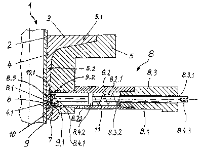
Figure 1 is one half of a lateral view in the cross-section
of an umbrella molded to a hollow core, together with the mold
and the ventilation valve according to the invention in the cast
condition of the umbrella;
Figure 2 is a view of a section of the ventilation valve
with the valve seat; and
Figure 3 is a view of the valve seat according to the
2a

CA 02298678 2000-O1-31
intersection I-I of Figure 2.
Reference number 1 indicates a part of an umbrella-type
insulator which has a core 2 or a core wall constructed as a
hollow body and an umbrella 3 molded thereto which has a molded-
on collar 4. The core 2 consists of an insulating material,
preferably silicone, which is reinforced by means of reinforcing
materials, particularly glass fibers. A one-piece or multi-piece
mold 5 is pushed over the core 2, which mold 5 has a funnel-
shaped mold space 5.1 shaped corresponding to the umbrella 3 with
the collar 4 to be molded. The portion 5.2 of the mold space 5.1
forming the collar 4 has a ring gap 6 at the collar end 4.1,
which ring gap 6 is closed off for the casting process by an
elastic seal 7, such as a ring seal or O-seal.
In the area of the collar end 4.1, a rod-like or pin-shaped
ventilation valve 8 is provided laterally in the mold 5, for
example, in the form of a disk valve or cone valve. The
ventilation valve 8 can be screwed into the mold 5 or may, for
example, by tightly inserted and fastened by means of a stud
screw or the like. The outer surface 8.1 of the ventilation
valve 8 advantageously extends to the surface of the umbrella 3
or to the surface 4.2 of the collar 4 of_ the umbrella 3. In
particular, it is flush with the surface of the mold 5.
3

CA 02298678 2000-O1-31
For producing an umbrella 3 with a collar 4, the mold 5 is
first placed at the assigned location on the core 2 or on the
core wall and is sealed off by means of the elastic seal 7.
Subsequently, the mold space 5.1 is filled from above with a
casting material which will then solidify to form an insulating
body. A suitable material is an unreinforced or reinforced
polymeric material, such as silicone, which is at first pourable
and then solidifies as the result of cross-linkage. During the
cross-linkage, this material bonds with the material of the core
2 or of the core wall. After the hardening or solidifying of the
cast-in material, the mold 5, together with the seal 7, is moved
downward in the drawing. In the resulting hollow space, a vacuum
is now formed which, in the absence of the valve 8, pulls the
umbrella 3 downward, particularly at the outer edge, whereby
tensions or even cracks may be formed on its top side.
According to the invention, the ventilation valve 8 is
constructed as a valve which, in the inoperative position, is in
the closed position. It consists of a rod-type or pin-shaped
valve housing 8.2 and of a valve body 8.3 which is screwed onto
this valve housing 8.2 in an axial extension or can be screwed
into this valve housing 8.2. In a preferably central bore 8.3.1,
which is coaxial to the valve space 8.2.1 of the valve housing
8.1, a connecting rod 8.4 is guided in a displaceable manner.
4

CA 02298678 2000-O1-31
The connecting rod 8.4 extends through the valve space
8.2.1. At the end 8.4.1 of the connecting rod 8.4, a valve
piston 9 is provided which has a seal 10. In the inoperative
position of the ventilation valve 8" the seal rests sealingly
against an orifice 8.5 of the outer surface 8.1 of the valve
housing 8.2, in that it is held in the closed position by way of
a pressure spring 11. For this purpose, the pressure spring 11
is clamped between a pressure surface 8.3.2 of the valve body 8.3
and a stop flange 8.4.2 provided in the area of the valve space
8.2.1 on the connecting rod 8.4, or is clamped on the rear side
9.1 of the valve piston 9.
By pulling on the end 8.4.3 protruding from the valve body
8.3, the connecting rod 8.4 can be pulled to the outside against
the force of the pressure spring 11; the seal 10 can be lifted
off the valve orifice 8.5; and the ventilation valve 8 can thus
be opened.
The valve housing 8.2 has an air inlet opening 8.2.2, by way
of which, when the ventilation valve 8 is open, air or another
gaseous medium can flow into the valve space 8.2.1 and can flow
out by way of the valve orifice 8.5. For a better air flow-
through, the valve piston 9 is preferably provided with lateral
overflow ducts 9.2 and optionally also the seal 10 is provided

CA 02298678 2000-O1-31
with correspondingly arranged lateral overflow ducts 10.1.
In the case of the illustrated system, the method of
operation of the ventilation valve 8 according to the invention
is as follows:
The initially described casting material is poured into the
mold 5. After the solidification of the casting material, the
mold 5, together with the elastic seal 7, is pushed downward in
the drawing. Simultaneously - or preferably, shortly before -,
the ventilation valve 8 is opened up and the mold 5 is ventilated
thereby, so that the cast umbrella 3 can easily and without any
damage be removed from the mold S.
An important advantage of the new ventilation valve 8
consists of the fact that the valve housing 8.2 can be placed in
the mold 5 and can be fastened in the mold 5, for example, by way
of a stud screw, while, on the other hand, the valve body 8.3
with the connecting rod 8.4, the pressure spring 11, the valve
piston 9 and the seal 10 can easily be detached from and taken
out of the valve housing 8.2. These removed parts can then be
cleaned outside the mold 5, if, for example, the overflow ducts
9.2 and/or 10.1 are clogged with the cast resin, particularly
silicone. Individual parts may also easily be replaced. The
6

CA 02298678 2000-O1-31
valve housing 8.2 therefore remains fixedly connected with the
mold 5. The cleaning and a possibly required replacement of
parts can therefore take place more rapidly and more conveniently
than in the case of a ventilation valve which forms a unit which
cannot be separated.
7

Dessin représentatif
Une figure unique qui représente un dessin illustrant l'invention.
États administratifs

2024-08-01 : Dans le cadre de la transition vers les Brevets de nouvelle génération (BNG), la base de données sur les brevets canadiens (BDBC) contient désormais un Historique d'événement plus détaillé, qui reproduit le Journal des événements de notre nouvelle solution interne.

Veuillez noter que les événements débutant par « Inactive : » se réfèrent à des événements qui ne sont plus utilisés dans notre nouvelle solution interne.

Pour une meilleure compréhension de l'état de la demande ou brevet qui figure sur cette page, la rubrique Mise en garde , et les descriptions de Brevet , Historique d'événement , Taxes périodiques et Historique des paiements devraient être consultées.

Historique d'événement

Description Date
Inactive : Périmé (brevet - nouvelle loi) 2018-07-29
Accordé par délivrance 2005-10-25
Inactive : Page couverture publiée 2005-10-24
Inactive : Taxe finale reçue 2005-08-10
Préoctroi 2005-08-10
Lettre envoyée 2005-06-17
Un avis d'acceptation est envoyé 2005-06-17
Inactive : Approuvée aux fins d'acceptation (AFA) 2005-05-27
Modification reçue - modification volontaire 2005-05-04
Inactive : Dem. de l'examinateur par.30(2) Règles 2005-01-28
Modification reçue - modification volontaire 2005-01-04
Lettre envoyée 2003-08-18
Exigences pour une requête d'examen - jugée conforme 2003-07-09
Requête d'examen reçue 2003-07-09
Modification reçue - modification volontaire 2003-07-09
Toutes les exigences pour l'examen - jugée conforme 2003-07-09
Lettre envoyée 2000-11-09
Inactive : Transfert individuel 2000-10-12
Inactive : Transferts multiples 2000-10-12
Inactive : Page couverture publiée 2000-03-29
Inactive : CIB en 1re position 2000-03-28
Inactive : Lettre de courtoisie - Preuve 2000-03-21
Inactive : Notice - Entrée phase nat. - Pas de RE 2000-03-14
Demande reçue - PCT 2000-03-13
Demande publiée (accessible au public) 1999-02-18

Historique d'abandonnement

Il n'y a pas d'historique d'abandonnement

Taxes périodiques

Le dernier paiement a été reçu le 2005-05-04

Avis : Si le paiement en totalité n'a pas été reçu au plus tard à la date indiquée, une taxe supplémentaire peut être imposée, soit une des taxes suivantes :

  • taxe de rétablissement ;
  • taxe pour paiement en souffrance ; ou
  • taxe additionnelle pour le renversement d'une péremption réputée.

Les taxes sur les brevets sont ajustées au 1er janvier de chaque année. Les montants ci-dessus sont les montants actuels s'ils sont reçus au plus tard le 31 décembre de l'année en cours.
Veuillez vous référer à la page web des taxes sur les brevets de l'OPIC pour voir tous les montants actuels des taxes.

Titulaires au dossier

Les titulaires actuels et antérieures au dossier sont affichés en ordre alphabétique.

Titulaires actuels au dossier
HAEFELY TRENCH MWB GMBH
TRENCH GERMANY GMBH
Titulaires antérieures au dossier
ALFONS LEICHT
HERMANN JEUTHNER
JOHANN GEORG WELZ
Les propriétaires antérieurs qui ne figurent pas dans la liste des « Propriétaires au dossier » apparaîtront dans d'autres documents au dossier.
Documents

Pour visionner les fichiers sélectionnés, entrer le code reCAPTCHA :


Pour visualiser une image, cliquer sur un lien dans la colonne description du document. Pour télécharger l'image (les images), cliquer l'une ou plusieurs cases à cocher dans la première colonne et ensuite cliquer sur le bouton "Télécharger sélection en format PDF (archive Zip)" ou le bouton "Télécharger sélection (en un fichier PDF fusionné)".

Liste des documents de brevet publiés et non publiés sur la BDBC .

Si vous avez des difficultés à accéder au contenu, veuillez communiquer avec le Centre de services à la clientèle au 1-866-997-1936, ou envoyer un courriel au Centre de service à la clientèle de l'OPIC.


Description du
Document 
Date
(aaaa-mm-jj) 
Nombre de pages   Taille de l'image (Ko) 
Description 2000-01-30 7 203
Abrégé 2000-01-30 1 17
Dessins 2000-01-30 1 35
Revendications 2000-01-30 3 61
Revendications 2005-01-03 3 69
Description 2005-01-03 8 225
Description 2005-05-03 8 227
Dessin représentatif 2005-06-09 1 18
Abrégé 2005-06-15 1 17
Avis d'entree dans la phase nationale 2000-03-13 1 193
Courtoisie - Certificat d'enregistrement (document(s) connexe(s)) 2000-11-08 1 113
Rappel - requête d'examen 2003-03-31 1 120
Accusé de réception de la requête d'examen 2003-08-17 1 173
Avis du commissaire - Demande jugée acceptable 2005-06-16 1 160
Correspondance 2000-03-13 1 14
PCT 2000-01-30 10 404
Correspondance 2005-08-09 1 31