Note: Descriptions are shown in the official language in which they were submitted.
~
. CA 02298691 2000-O1-28
1:
PCT/EP98/04433
Alfing Kessler Sondermaschinen GmbH July 23, 1999
Apparatus for Crack Splitting
a Big-End Cap and Rod of a Connecting Rod
The present invention relates to an apparatus for crack
splitting a big-end cap and rod of a connecting rod,
cluding a fixed expander mandrel half o xed part of
the apparatus, a movable er mandrel half on a part
of the ap a movable in the expanding direction and
as set forth in the preamble of claim 1.
Known from EO 0 396 797 is an apparatus for crack split-
ting rod and cap, comprising advanceable supporting ele-
ments on both the movable and fixed part of the apparatus.
In this known prior art the advanceable supporting ele-
ments are formed by set screws (illustrated symbolically
as grub screws). Turning the set screws permits advancing
the supporting elements to tension the connecting rod to
be split relative to the fixed and movable expander man-
drel half and in the apparatus. Experience has shown that
clamping in place the connecting rod to be split, espe-
cially to prevent it from turning out of place, is ne-
cessary to achieve a defined crack with no negative
bending effects.
With the advanceable supporting elements it is also pos-
sible to set the apparatus for crack splitting rod and cap
of a connecting rod differing in size. In addition, with
the advanceable supporting elements differences due to
manufacturing tolerances can also be compensated.
CA 02298691 2000-O1-28
Z
To achieve speedy adaptation powered advanceable sup-
porting elements are known from prior art.
In the case of both manual set screws and of powered ad-
vanceable supporting elements there is the problem that
the advanceable supporting elements provided on the mov-
able part of the apparatus are exposed to shock and vi-
bration automatically involved in the crack splitting.
Thus, in splitting, the two expander mandrel halves are
usually urged apart with the aid of a cleaving wedge. This
movement and splitting of the cap from the rod occurs ab-
ruptly. In addition the movable part of the apparatus im-
pacts a stop at which the movement of the movable part of
the apparatus is halted. It is especially powered ad-
vanceable supporting elements that are heavily stressed by
this action, resulting in problems with proper functioning
and long useful life.
an apparatus for crack splitting a big-end cap d rod
with a long useful life with no functionin roblems and
with which the big-end cap can be spli rom the rod with
high precision.
This object is achiev in accordance with the invention
by an apparatus aracterized in that the advanceable sup-
porting el ents are arranged on a fixed part of the ap-
para and the fixed supporting elements are arranged on
Z .~J
Known from DE-A-43 16 354 is an apparatus for crack split-
ting rod and big-end cap of a connecting rod; including a
fixed expander mandrel half on a fixed part of the ap-
paratus; with a movable expander mandrel half on a part of
the apparatus movable in the expanding direction; with a
cleaving wedge arranged for being powered forwards between
the expander mandrel halves for parting the expander man-
CA 02298691 2000-O1-28
drel halves from each other in the expanding direction;
and including a fixed supporting element for the rod ar-
ranged on the movable part of the apparatus and with an
advanceable supporting element for the cap arranged on the
fixed part of the apparatus.
D2 (US-A-5105538) discloses an apparatus for crack split-
ting the rod and annular cap of a connecting rod; in-
cluding a fixed expander mandrel half on a fixed part of
the apparatus; with a movable expander mandrel half on a
part of the apparatus movable in the expanding direction,
and with supporting elements for rod and cap. The movable
part of the apparatus is designed to accommodate the cap
and the fixed part of the apparatus to accommodate the
rod. The supporting element for the rod is formed by a
slide having a notch for contacting the outer cir-
cumference of the small-end of the rod. The supporting
element for the cap is an advanceable flexible supporting
element arranged on the movable part of the apparatus,
this supporting element acting centered on the outer cir-
cumference of the cap. The apparatus is provided fur-
thermore with two side supporting elements arranged on the
side opposite the cap supporting element, i.e. on the
fixed part of the apparatus. Of these side supporting ele-
ments one is fixed and the other is advanceable laterally
to a lateral stop surface area of the cap for flexible
contact therewith. In the region of the fixed supporting
element the fixed part of the apparatus is canted so that
it protrudes partly beyond the annular contour of the cap
without contacting it, however. The apparatus is provided
further with opposing side stops or defining elements
fixedly arranged on the movable part of the apparatus on
both sides of the flexible cap supporting element. These
stops are not in contact with the part to be crack split,
they instead being first positioned slightly spaced away
from the cap so that they do not function as a stop for
two shoulder portions of the parted part of the cover un-
CA 02298691 2000-O1-28
Y
til directly following cracking and define a further con-
tinued movement of the parted cap part. The side stops are
advanceable only in common. However, their advancement may
be done irrespective of advancement of the flexible stop.
The ends of the side stops facing the cap are bevelled so
that they contactlessly accommodate between them a side
rounded portion of the cap and partly protrude there-
beyond. Thus, in this apparatus the actual support or
clamping of the connecting rod is done merely via the
notch for the small-end (rod end) and the single flexible
cap supporting element. The side supporting elements serve
merely to provide a certain lateral stabilization. The
side stops function merely as elements defining or
stopping the parted cap part.
advanceable supporting elements differences due to~u-
facturing tolerances can also be compensated ~.
To achieve speedy adaptation powered advancea a support-
ing elements are known from prior art.
In the case of both manual setscrew and of powered ad-
vanceable supporting elements the is the problem that
the supporting elements provid on the movable part of
the apparatus are exposed shock and vibration auto-
matically involved in t a crack splitting. Thus, in
splitting, the two ex nder mandrel halves are usually
urged apart with a aid of a cleaving wedge. This
movement and sp tting the cap from the rod occurs
abruptly. In dition the movable part of the apparatus
impacts a s op at which the movement of the movable part
of the a aratus is halted. It is especially powered ad-
vance le supporting elements that are heavily stressed by
th' action, resulting in problems with proper functioning
CA 02298691 2000-O1-28
z8 5
The present invention is based on the object of providing
an apparatus for crack splitting a big-end cap and rod
with a long useful life with no functioning problems and
with which the big-end cap can be split from the rod with
high precision.
This object is achieved in accordance with the invention
by an apparatus
porting elements are arranged on part of the
apparatus and th supporting elements are arranged
having the features of claim 1. Further advantageous
aspects of the apparatus in accordance with the invention
are the subject matter of the sub-claims.
CA 02298691 2000-O1-28
.~.._.~~~~.wg.~.~'.~ ..Sa.~.~.~.he.~.~p~~x'dt'L.I's._.~..exp~y,~~~Mahn~k ~~~-
~,
tion automatically involved in the crack splitting. Th~:~,
in splitting, the two expander mandrel halves are usually
urged apart with the aid of a cleaving wedget. This
movement and splitting of the cap from the,r~'rod occurs
abruptly. In addition the movable part of..~ftrhe apparatus
impacts a stop at which the movement ofy,-'the movable part
of the apparatus is halted. It is es.~~cially powered ad-
vanceable supporting elements that ire heavily stressed by
this action, resulting in problemsrwith proper functioning
and long useful-life.
The present invention is.,based on the object of providing
an apparatus for crackt~splitting the rod (shaft) and big-
end cap of a connecting rod with a long useful life with
no functioning prgblems and with which rod and the big-end
cap of a connect''ing rod can be split with high precision.
This objecj~ is achieved in accordance with the invention
by an a aratus characterized in that the advanceable sup-
portielements are arranged on a fixed part of the ap-
par~tus and the fixed supporting elements are arranged on
part of''th~--a~~~ ~.
The gist of the invention is to provide the advanceable
supporting elements, automatically exposed to more stress,
on the fixed part of the apparatus to thus significantly
reduce the problems involved in reliable functioning and
long useful life. This is particulary important where use
is made of powered advanceable supporting elements. These
are usually powered by pneumatic or hydraulic cylinders or
by electric motor drives which are not only in themselves
sensitive to shock and vibration but also incorporate
flexible input and output tubing for supply and control.
Flexible input and output tubing in pneumatic, hydraulic
or electric motor drives are particularly sensitive to
shock and vibration and cyclic stresses of reciprocating
CA 02298691 2000-O1-28
operation. Arranging these sensitive parts on the fixed
part of the apparatus in accordance with the invention
avoids the resulting loads and at least the influence of
direct shock and vibration which is particularly damaging
to flexible tubing and electric wiring.
Since the big-end caps of connecting rods always need to
comprise outer contact surface areas for the bolts for
connecting rod and cap, the cap can be supported par-
ticularly effectively at these contact surface areas. It
is thus proposed in one preferred embodiment of the pre-
sent invention that the fixed part of the apparatus is
equipped to mount the cap and the movable part of the ap-
paratus to mount the rod.
In this arrangement the rod is held particular simply and
effectively in the apparatus when at least one fixed sup-
porting element is formed by a locating peg for mounting
the small-end bore of the rod.
As an alternative the fixed supporting element may also be
formed by a recess contacting suitable portions of the
outer surface area of the rod end (small end) at least in
part.
One particularly effectively actuation of the advanceable
supporting elements is provided in that they contact at
least one wedge element shiftable substantially trans-
versely to the advance movement. Such an arrangement en-
ables a particular rigid arrangement to be achieved for
loading.
Advantageously in this arrangement two supporting elements
are provided and a wedge element assigned to each sup-
porting element. Thus it is possible to benefit from the
advantages of wedge actuation whilst simultaneously
CA 02298691 2000-O1-28
clamping the connecting rod reliably in place at two
opposite locations.
By adapting the advance movement of each supporting ele-
ment to uniformly clamp in place the connecting rod to be
split, both wedge elements comprise wedge surface areas
having an identical angle of attack. This thus achieves
for both supporting elements an identical advance movement
in such a configuration when both wedge elements are
shifted by the same amount.
Production tolerance inaccuracies on the part of the con-
necting rod to be supported can now be compensated in that
two advanceable supporting elements are provided, each of
which can be advanced independently of the other. Due to
the two supporting elements, each advanceable indepen-
dently of the other, each connecting rod part to be
fixedly secured can be individually set.
Auto-centering by actuating the wedge elements is simply
achieved in that the wedge surface areas of the wedge ele-
ments are arranged opposite in angle of attack and in that
a hydraulic or pneumatic cylinder is provided whose face
cooperates with the one wedge element and whose piston
cooperates with the other wedge element.
However, a particularly effective actuation of the ad-
vanceable supporting elements is also achievable by
direct-acting hydraulic cylinders. This enables each sup-
porting element in such a case to be connected to the
piston rod of a supporting piston. This connection is con-
figured to advantage such that each of the supporting
elements may be arranged directly at the front end of the
piston rod of the pistons.
For loading the connecting rods into the crack splitting
apparatus numerous proposals exist in prior art. One fur-
. CA 02298691 2000-O1-28
ther development in the sense of the object of the present
invention is, however, achieved with such a loading device
with which the crack splitting apparatus is located sub-
stantially stationary whilst the connecting rods are
inserted therein. In such a configuration the pneumatic or
hydraulic cylinders or the electric motor drives including
the feed and discharge lines for supply and control can be
stationary whilst loading is achieved exclusively by
moving the connecting rod.
There are basically two possibilities available for the
loading arrangement. In the one possibility a transport
means may be arranged above the stationary apparatus for
overhead insertion/removal of the connecting rod into/from
the apparatus.
In the other possibility a clocked transport means is pro-
vided under the stationary apparatus from which the con-
necting rod is picked out for insertion into the ap-
paratus, held in the apparatus during crack splitting, and
then lowered back into the transport means.
To protect the sensitive drive system including the feed
and discharge lines also from indirect shock and vibration
it is further expedient to provide a baseframe on which
the apparatus is mounted via shock absorbers.
Embodiments of the invention will now be detailled for
further explanation and a better understanding of the in-
vention with reference to the attached drawings in which:
Fig. 1 is a schematic partially sectioned plan view of
a first example embodiment of the apparatus in
accordance with the invention,
Fig. 2 is a schematic partially sectioned detail view
CA 02298691 2000-O1-28
/0
of a second example embodiment of the apparatus
in accordance with the invention, and
Fig. 3 is a schematic partially sectioned plan view of
a third example embodiment of the apparatus in
accordance with the invention.
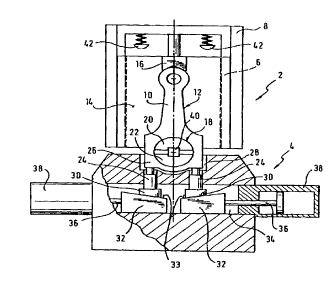
Referring now to Fig. 1 there is illustrated the first
example embodiment of an apparatus in accordance with the
invention comprising a movable part 2 and a fixed part 4
of the apparatus. The movable part 2 of the apparatus is
guided longitudinally on a frame 8 via guides 6, shown
schematically, so that the movable part 2 of the apparatus
reciprocates on the frame 8 like a slide. The frame 8 as
well as the fixed part 4 of the apparatus are held secured
in place on a common baseframe (not shown).
Retained in the movable part 2 of the apparatus is a rod
of a connecting rod 12 to be split. For this purpose
the movable part 2 of the apparatus comprises a sub-
stantially flat retaining surface area 14 on which the
connecting rod 12 rests. Furthermore the movable part of
the apparatus comprises a supporting element which in this
case is configured as a vee block 16 (prism holder) whose
retaining surface areas are at least partly in contact
with the outer surface area of the connecting rod small-
end of the rod 10. As an alternative the rod 10 may be
locked to prevent it turning out of place by a fixed pin
protruding into the small-end bore of the connecting rod.
Engaging a bore 18 of the connecting rod 12 are two ex-
pander mandrel halves 20, 22. The expander mandrel half 20
is secured to the movable part 2 of the apparatus and pro-
trudes beyond the retaining surface area 14. Accordingly,
the connecting rod 12 to be split is retained in the
region of the rod, on the one hand, by the vee block 16
CA 02298691 2000-O1-28
//
protruding beyond the retaining surface area 14 and, on
the other by the expander mandrel half 20.
On the fixed part 4 of the apparatus the connecting rod 12
to be split is clamped in place between the expander man-
drel half 22 and two advanceable supporting elements dis-
posed spaced away from each other which in the present
example are formed by two pins 24 guided in the longi-
tudinal direction of the connecting rod 12 to be split. As
evident from Fig. 1 the two pins 24 engage the contact
surface areas of a big-end cap 26 of the connecting rod
12. These contact surface areas are needed in later as-
sembly of the connecting rod 12 for j oining rod and big-
end cap together for contacting the heads of the tie-
bolts.
It is evident from Fig. 1 that the big-end cap 26 of the
connecting rod 12 is clamped in place merely between the
expander mandrel half 22 and the two pins 24. The fixed
part 4 of the apparatus comprises in addition in the
region of the cap a recess 28 into which the big-end cap
26 of the connecting rod 12 can be inserted with no prob-
lem when the pins 24 are retracted.
Whilst the front face of the advanceable pins 24 is in
contact with the cap 26 the rear ends of the pins 24 are
flared into a contact piece 30, each contacting a wedge
element 32 via its wedge surface area 33. Each wedge ele-
ment 32 is shiftingly held in a recess 34 oriented sub-
stantially perpendicular to the longitudinal axis of the
connecting rod 12 and supported at the surface of the re-
cess 34 relative to the fixed part 4 of the apparatus.
Each wedge element 32 cooperates via a piston rod 36 with
a double-ended hydraulic cylinder 38.
To split the big-end cap 26 from the rod 10 of a con-
necting rod 12 the latter is mounted by its bore 18 on the
CA 02298691 2000-O1-28
~.
adjoining expander mandrel halves 20, 22. In this ar-
rangement the connecting rod 12 is oriented so that the
outer surface area of the rod-end is inserted in the vee
block 16.
After this, the connecting rod 12 is clamped in place. For
this purpose the hydraulic cylinders 38 are energized so
that the two wedge elements 32 are moved towards each
other. The contact pieces 30 slide on the inclined wedge
surface area 33. This results in the guided pins 24 being
advanced in the direction of the connecting rod 12. Due to
the connecting rod being defined between the vee block 16
and the two expander mandrel halves 20, 22 the connecting
rod is arranged such that the front faces of the pins 24
are urged against the contact surface areas of the big-end
cap 26.
To uniformly clamp the connecting rod in place between the
expander mandrel half 22 and the pins 24 the hydraulic
cylinders 38 can be energized individually. By sensing the
internal pressure in each hydraulic cylinder 38 the force
with which each pin 24 is urged against the cap 26 can be
controlled. This makes a uniform clamping in place of the
connecting rod 12 possible.
Once the connecting rod 12 has been inserted in the ap-
paratus and clamped in place via the pins 24, the actual
splitting follows as known from prior art. For this pur-
pose a cleaving wedge 40 disposed between the the expander
mandrel halves 20, 22 is powered forwards to part the two
expander mandrel halves 20, 22 from each other. On rupture
of the joint between rod 10 and cap 26 the movable part 2
of the apparatus distances itself from the fixed part 4 of
the apparatus abruptly. This sudden movement is cushioned
by spring stops 42 secured to the frame 8.
CA 02298691 2000-O1-28
~3
The connecting rod now split can then be removed from the
apparatus. This first requires the wedge elements 32 to be
retracted via the hydraulic cylinders 38 to release the
tension on the cap 26. After this the rod 10 and the cap
26 can be lifted out of the apparatus either manually or
automatedly.
Referring now to Fig. 2 there is illustrated a detail of a
second example embodiment of the present invention on a
magnified scale. It is to be noted that like components as
in Fig. 1 are identified by like reference numerals in
Fig. 2.
The example embodiment as shown in Fig. 2 differs sub-
stantially from the example embodiment as shown in Fig. 1
by the two wedge elements 32 being powered by a common hy-
draulic cylinder 44. In the example embodiment as shown in
Fig. 2 the hydraulic cylinder 44 is fixedly connected to a
wedge element 32, whereas the other wedge element 32 co-
operates with the hydraulic cylinder 44 by a piston rod 46
which penetrates the first wedge element and is connected
to a piston 48 sealed in the cylinder 44.
The two wedge surface areas 33 in the example embodiment
shown have an identical angle of attack relative to the
sliding plane of the wedge elements 32. In addition the
wedge elements are disposed opposingly inclined relative
to each other.
Advancing the pins 24 to clamp the big-end cap 26 in place
results in the two wedge elements 32 being moved towards
each other, this advance movement actuation being possible
with the aid of just a single hydraulic cylinder 44. Due
to the geometry of the hydraulic cylinder 44 a substan-
tially identical advancing force acts on the two wedge
elements 32. In this arrangement, this simple design fea-
CA 02298691 2000-O1-28
1~
ture thus achieving that each of the two pins 24 is in
contact with the cap 26 with identical force.
To release the tension on the cap 26 once it has been
split from the rod 10, the two wedge elements 32 are
forced away from each other by actuation of the cylinder
44. Stops (not shown) defining this movement of the wedge
elements 32 prevent merely one wedge element being shifted
whilst the other wedge element remains in place. This thus
ensures that both pins 24 are distanced from the expander
mandrel half 22 to make room for inserting a new con-
necting rod.
Referring now to Fig. 3 there is illustrated a third
example embodiment comprising supporting elements 24 in
the form of pins, each arranged directly at the front end
of the piston rods 50 of hydraulic supporting pistons 51.
The positioning of the pistons is sensed by a sensor means
52 indicated merely schematically in Fig. 3.
The pistons rods 50 and the pistons 51 are mounted in a
cylinder housing 53 arranged on the fixed part 4 of the
apparatus.
During crack splitting the supporting elements 24 are
maintained in contact with the big-end cap 26 of the con-
necting rod 12 by a controlled hydraulic pressure. Re-
traction of each supporting element 24 during crack split-
ting is assured by a separate controlled check valve 54
sealingly arranged on the cylinder housing 53.