Note: Descriptions are shown in the official language in which they were submitted.
CA 02298753 2000-02-11
1
DUAL BRAKE VALVE FOR A STEERING ASSIST SYSTEM
Field of the Invention
The present invention relates generally to steering assist systems.
More particularly, the present invention relates to hydraulic valving
arrangements for
steering assist systems or other systems where precise equal braking pressures
are
desirable.
Background of the Invention
Steering assist vehicles are advantageous because they are highly
maneuverable. A typical steering assist vehicle is turned by driving the
wheels on
one side of the vehicle at a different speed than the wheels on the other side
of the
vehicle. Also, turning can be achieved by stopping the wheels on one side of
the
vehicle, while driving the wheels on the other side of the vehicle. When
braking a
steering assist vehicle, it is desirable to have equal braking pressures on
both sides of
the vehicle to prevent unintentional turning. Examples of typical steering
assist
vehicles include farm tractors, construction backhoe loaders, farm combines,
as well
as other vehicles.
Summar,y of the Invention
One aspect of the present invention relates to a valve arrangement for
use with a steering assist system having left and right actuating members. The
valve
arrangement includes a valve body defining a left brake port adapted for
connection
to a left hydraulic brake and a right brake port adapted for connection to a
right
hydraulic brake. The arrangement also includes a left brake valve member for
controlling hydraulic fluid flow through the left brake port, and a right
brake valve
member for controlling hydraulic fluid flow through the right brake port. The
left
and right brake valve members are adapted to the actuated, respectively, by
left and
right brake actuating members. The valve arrangement also includes means for
providing the highest pressure present at either of the first and second brake
valve
members to both the first and second brake ports, wherein equal braking
pressures
are provided to the first and second brakes even when the first and second
brake
actuating members have been actuated unequal amounts.
Another aspect of the present invention relates to a steering assist
system including left and right hydraulic brakes, and left and right actuating
members for respectively actuating the left and right brakes. The system also
includes a valve body defining a left brake port connected to the left
hydraulic brake
and a right brake port connected to the right hydraulic brake. The valve body
also
CA 02298753 2000-02-11
2
defines left and right brake pressure ports connected to a source of hydraulic
pressure. The valve body further defines a left brake passageway for providing
fluid
communication between the left brake pressure port and the left brake port,
and a
right brake passageway for providing fluid communication between the right
brake
pressure port and the right brake port. The steering system further includes a
left
brake valve member for controlling hydraulic fluid flow through the left brake
port
and through the left brake pressure port, and a right brake valve member for
controlling hydraulic fluid flow through the right brake port and through the
right
brake pressure port. The left and right brake valve members are respectively
operatively coupled to corresponding left and right brake actuating members. A
bypass passage arrangement provides fluid communication between the left brake
passageway and the right brake port, and also provides fluid communication
between
the right brake passageway and the left brake port. A plurality of valves
function to:
(1) close the left brake passageway and direct hydraulic fluid from the right
brake
passageway through the bypass passage arrangement to the left brake port when
the
right brake actuating member has been actuated more than the left brake
actuating
member; and (2) close the right brake passageway and direct hydraulic fluid
from the
left brake passageway through the bypass passage arrangement to the right
brake
port when the left brake actuating member has been actuated more than the
right
brake actuating member.
A variety of advantages of the invention will be set forth in part in the
description that follows, and in part will be apparent from the description,
or may be
learned by practicing the invention. It is to be understood that both the
foregoing
general description and the following detailed description are exemplary and
explanatory only and are not restrictive of the invention as claimed.
Brief Description of the Drawings
The accompanying drawings, which are incorporated in and
constitute a part of this specification, illustrate several aspects of the
invention and
together with the description, serve to explain the principles of the
invention. A
brief description of the drawings is as follows:
Fig. 1 is a schematic representation of an embodiment of a braking
system including a brake valve in accordance with the principles of the
present
invention, push rods of the brake valve are shown in first, neutral positions;
Fig. 2 is a schematic representation of the system of Fig. 1 with the
push rods oriented in second positions;
Fig. 3 is a schematic representation of the system of Fig. 1 with the
push rods in third positions;
CA 02298753 2000-02-11
3
Fig. 4 is a schematic representation of the system of Fig. 1 with the
push rods in fourth positions;
Fig. 5 is a schematic representation of the system of Fig. 1 with the
push rods in fifth positions;
Fig. 6 is a schematic representation of the system of Fig. 1 with more
actuating pressure being applied to the left push rod than the right push rod;
Fig. 7 is a schematic representation of the system of Fig. 1 with more
actuating pressure being applied to the right push rod than the left push rod;
Fig. 8 is a schematic representation of the brake valve of Fig. 1 with
the left push rod actuated and the right push rod in the neutral position;
Fig. 9 is a schematic representation of the brake valve of Fig. 1 with
the right push rod actuated and the left push rod in the neutral position;
Fig. 10 is perspective view of an embodiment of a dual brake valve in
accordance with the principles of the present invention;
Fig. 11 is a bottom view of the brake valve of Fig. 10;
Fig. 12 is a cross-sectional view taken along section line 12-12 of
Fig. 11;
Fig. 13 is a cross-sectional view taken along section line 13-13 of
Fig. 12; and
Fig. 14 is a cross-sectional view taken along section line 14-14 of
Fig. 13.
Detailed Description of the Preferred Embodiment
Reference will now be made in detail to exemplary aspects of the
present invention that are illustrated in the accompanying drawings. Wherever
possible, the same reference numbers will be used throughout the drawings to
refer
to the same or like parts.
Fig. 1 is a schematic representation of an embodiment of a steering
assist system 20 in accordance with the principles of the present invention.
The
steering assist system 20 includes a full power dual brake valve 22 for
controlling
hydraulic fluid pressure to left and right hydraulic brakes 24L and 24R.
Hydraulic
fluid (e.g., hydraulic oil) for pressurizing the brakes 24L and 24R is stored
in a
conventional reservoir or tank 26. Pressurized hydraulic fluid from the tank
26 is
provided to the dual brake valve 22 by a source of pressure such as an
accumulator
28. Preferably, a pump (not shown) is used to direct the hydraulic fluid from
the
tank 26 to the accumulator 28. The steering assist system 20 also includes
left and
right actuating members 3 0L and 3 0R (e.g., pedals or manual levers) for
selectively
CA 02298753 2000-02-11
4
actuating the dual brake valve 22 to either activate or deactivate the
hydraulic brakes
24L and 24R.
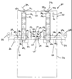
The dual brake valve 22 of the steering assist system 20 includes a
valve body 32. The valve body 32 defines left and right push rod chambers 34L
and
34R. The push rod chambers 34L and 34R are substantially parallel and
generally
cylindrical in shape. Left and right push rods 36L 36R are respectively
mounted in
the left and right push rod chambers 34L and 34R. The push rods 36L and 36R
are
adapted to slide axially within the push rod chambers 34L and 34R. Preferably,
the
push rods 36L and 36R are mechanically coupled, respectively, to the left and
right
actuating members 30L and 30R. By depressing or otherwise moving the actuating
members 30L and 30R, the push rods 36L and 36R are axially moved within the
rod
chambers 34L and 34R to provide selective activation and deactivation of the
left and
right hydraulic brakes 24L and 24R.
The valve body 32 also defines a plurality of fluid passageways for
conveying hydraulic fluid. For example, the valve body 32 defines left and
right
brake passages or ports 38L and 38R, left and right tank passages or ports 40L
and
40R, and left and right pressure passages or ports 42L and 42R. The left
brake, tank
and pressure ports 38L, 40L and 42L are each separate from one another and
preferably extend from an exterior from the valve body 32 to the left push rod
chamber 34L. Similarly, the right brake, tank and pressure ports 38R, 40R and
42R
are preferably separate from one another and extend from the exterior of the
valve
body 32 to the right push rod chamber 34R. It will be appreciated that
hydraulic
hoses are preferably used to provide fluid communication between the brake
ports
38L, 38R and the hydraulic brakes 24L, 24R, between the tank ports 40L, 40R
and the
tank 26, and between the pressure ports 42L, 42R and the accumulator 28.
Pressure switches 44 are used to sense the pressure within the
pressure ports 42L and 42R. Preferably, the pressure switches 44 activate a
warning
signal if the pressure within the pressure ports 42L and 42R falls below a
predetermined level.
The valve body 32 also defines an interior passage arrangement
located between the left and right push rod chambers 34L and 34R. For example,
the
passage arrangement includes left and right check valve passages 46L and 46R.
Left
and right check valves 48L and 48R respectively control flow through the left
and
right check valve passages 46L and 46R. The valve body 32 also defines first
and
second interior left ports 50L, 50R and first and second interior right ports
50R, 50L.
The left ports 50L and 52L provide fluid communication with the left
push rod chamber 34L, and the right ports 50R and 52R provide fluid
communication
with the right push rod chamber 34R. A left brake passageway 54L loops from
the
CA 02298753 2000-02-11
left port 52L through the check valve passage 46L to the left port 50L. The
check
valve 48L allows flow through the check valve passage 46L in a direction
toward the
port 50L, and prevents flow in an opposite direction through the check valve
passage
46L. A similar right brake passageway 54R loops from the right port 52R
through the
5 check valve passage 46R to the right port 50R. The check valve 48R allows
flow
through the check valve passage 46R in a direction toward the port 50R, and
prevents
flow through the check valve passage 46R in the opposite direction.
The valve body 32 further defines first and second cross-
passageways 56 and 58 that extend between the check valve passageways 46L and
46R. The first cross-passageway 56 is located on the upstream sides of the
check
valves 48L and 48R (i.e., the passageway 56 is located on the same side of the
check
valves 48L and 48R as the ports 50L and 50R). The second cross-passageway 58
is
located on the downstream side of the check valves 48L, 48R, (i.e., the
passageway
58 is located on the same side of the check valves 48L, 48R as the ports 52L
and 52R).
A bypass line 60 interconnects the first and second cross-passageways 56 and
58.
The bypass line 60 is shown as being generally parallel with respect to the
check
valve passages 46L and 46R. A shuttle valve 62 is located at the intersection
between
the second cross-passageway 58 and the bypass line 60. Left and right orifices
64L
and 64R are located along the first cross-passageway 56. The left orifice 64L
is
located between the bypass line 60 and the left check valve passage 46L, and
the
right orifice 64R is located between the bypass line 60 and the right check
valve
passage 64R. The orifices preferably have diameters in the range of.035-.039
inches, and are preferably about .08 inches long. Of course, the dimensions
are
application specific and may vary depending upon the particular application in
which
the valve configuration is being used.
The valve further defines left and right hydraulic pilot passages 66L
and 66R that respectively extend from ports 52L, 52R to left and right
hydraulic pilot
volumes 68L and 68R. In use of the dual brake valve 22, pressurized hydraulic
fluid
from the accumulator 28 travels through the hydraulic pilot passages 66L and
66R
and into the hydraulic pilot volumes 68L and 68R. The pressurized hydraulic
fluid
within the hydraulic pilot volumes 68L and 68R applies axial pressure or
loading
upon the push rods 36L and 36R in a direction opposite to the actuating forces
provided by the actuating members 30L and 30R (i.e., toward the neutral
positions of
Fig. 1).
The steering assist system 20 also includes left and right spring
assemblies 70L and 70R that form force transfer mechanisms between the
actuating
members 30L, 30R and the push rods 36L, 36R. For example, if an operator
slightly
depresses the actuating members/pedals 30L, 30R, the spring assemblies 70L and
70R
CA 02298753 2000-02-11
6
transfer relatively small axial loads to the push rods 36L, 36R. If the
operator pushes
harder on the actuating members/pedals 30L, 30R, the spring assemblies 70L and
70R
transfer larger axial loads to the push rods 36L, 36R. The axial spring forces
transferred by the spring assemblies 70L, 70R are balanced by equal and
opposite
forces provided by pressurized hydraulic fluid within the hydraulic pilot
volumes 68L
and 68R.
The spring assemblies 70L, 70R are positioned within spring chambers
72L, 72R. The spring chambers 72L, 72R are typically filled with hydraulic
fluid that
is maintained at tank pressure. A passageway 73 interconnects the two spring
chambers 72L, 72R. A check ba1174 is used to close fluid communication between
the spring chambers 72L, 72R and the tank 26 at the time of brake release. By
blocking flow between the tank 26 and the chambers 72L, 72R , the check ba1174
inhibits pedal/actuating member kick-back caused by increased tank line
pressure
during brake release. It will be appreciated that the chambers 72L, 72R need
not be
filled with hydraulic fluid. However, hydraulic fluid commonly enters the
chambers
72L, 72R via leakage along the push rods 36L, 36R. Additionally, hydraulic
fluid can
also enter the chambers 72L, 72R by flowing past the check ball 74 before the
ball 74
reaches a closed position.
Figs. 1-5 illustrate the dual brake valve 22 with the push rods 36L and
36R oriented in five different positions. For example, Fig. 1 shows each of
the push
rods 36L and 36R in a neutral first position. When the push rods 36L and 36R
are in
the first positions, the brake ports 38L and 38R are in fluid communication
with the
left and right ports 52L and 52R, and the tank 26 is in fluid communication
with the
brake ports 38L, 38R and the left and right ports 52L, 52R. Additionally, the
pressure
ports 42L, 42R and the left and right ports 50L, 50R are closed. In such a
configuration, the check valves 48L, 48R are biased closed, the shuttle valve
62 is in
a central position, and the entire dual brake system is at tank pressure.
Fig. 2 shows each of the push rods 361_, 36R in a second position.
With the push rods 36L, 36R in the second position, the tank ports 40L, 40R
are
respectively in fluid communication with the left and right ports 52L, 52R.
Additionally, the brake ports 38L, 38R, the pressure ports 42L, 42R, and the
left and
right ports 50L, 50R are closed.
Fig. 3 shows each of the push rods 361,, 36R in a third position. When
the push rods 36L, 36R are in the third positions, the brake ports 38L, 38R
are in fluid
communication with their corresponding ports 50L, 50R, and the tank ports 40L,
40R
are in fluid communication with their corresponding ports 52L, 52R.
Additionally,
the pressure ports 42L, 42R are closed.
CA 02298753 2000-02-11
7
Fig. 4 shows each of the push rods 36L, 36R in a fourth position.
When each push rod 36L, 36R is in the fourth position, the brake ports 38L,
38R are in
fluid communication with their corresponding ports 50L, 50R. Additionally, the
tank
ports 40L, 40R, the pressure ports 42L, 42R and the ports 52L, 52R are closed.
Fig. 5 shows each of the push rods 36L, 36R in a fifth position. When
each of the push rods 36L, 36R is in the fifth position, the brake ports 38L,
38R are in
fluid communication with their corresponding ports 50L, 50R, the pressure
ports 42L,
42R are in fluid communication with their corresponding ports 52L, 52R, and
the tank
ports 40L, 40R are closed. In such a configuration, pressurized hydraulic
fluid from
the accumulator 28 flows through the pressure ports 42L, 42R, through the
brake
passageways 54L, 54R , and through the brake ports 38L, 38R, to the hydraulic
brakes
24L, 24R thereby causing the brakes 24L, 24R to be activated.
By way of example, an operator can use the steering assist system 20
to brake a vehicle by depressing or otherwise moving the actuating members
30L,
30R such that the push rods 36L, 36R are moved by the spring assemblies 70L,
70R to
the fifth position shown in Fig. 5. As described above, when each push rod
36L, 36R
is in the fifth position, pressurized hydraulic fluid from the accumulator 28
travels
through the dual brake valve 22 and causes the hydraulic brakes 24L, 24R to be
activated. The pressurized hydraulic fluid from the accumulator 28 also flows
through the hydraulic pilot passages 66L, 66R causing the hydraulic pilot
volumes
68L, 68R to be pressurized. The pressure within the hydraulic pilot volumes
68L, 68R
causes the push rods 36L, 36R to move, against the forces provided by the
spring
assemblies 70L, 70R, from the fifth position of Fig. 5 to the fourth position
of Fig. 4.
At the fourth position of Fig. 4, the axial forces applied by the hydraulic
fluid in the
hydraulic pilot volumes 68L, 68R preferably balance the axial forces applied
by the
spring assemblies 70L, 70R .
When each push rod 36L, 36R is in the fourth position, the pressure
ports 42L, 42R are closed and a modulated brake pressure (i.e., a brake
pressure that
is at least slightly less than the pressure provided by the accumulator 28) is
provided
to the brakes 24L, 24R. The modulated pressure is provided because the
movement
of each push rod 36L, 36R from the fifth position to the fourth position at
least
slightly increases the volume of the hydraulic pilot volumes 68L, 68R while
the
pressure ports 42L, 42R are closed thereby at least slightly reducing the
pressure
supplied to the brakes 24L, 24R.
Thereafter, the push rods 36L, 36R will float between the five
positions shown in Figs. 1-5 depending upon the amount of pressure the
operator
supplies to the push rods 36L, 36R through the actuating members 30L, 30R and
the
spring assemblies 70L, 70R. For example, if the operator releases all pressure
from
CA 02298753 2000-02-11
8
the actuating members 30L, 30R, the push rods 36L, 36R will return to the
neutral
position of Fig. 1 and the hydraulic brakes 24L, 24R will be deactivated. If
the
operator reduces only some of the pressure applied to the actuating members
30L,
30R, the push rods 36L, 36R will float to one of the intermediate positions
between
the first positions and the fifth positions until the hydraulic forces
provided by the
pressurized fluid within the hydraulic pilot volumes 68L, 68R balance the
spring
forces provided by the spring assemblies 70L, 70R . If the operator increases
the
pressure applied to the actuating members 30L, 30R, the push rods 36L, 36R
will move
to the fifth positions until the pressure within the hydraulic pilot volumes
68L, 68R
exceeds the spring loads provided by the spring assemblies 70L, 70R and force
the
push rods 36L, 36Rto positions where the push rods are force balanced.
A pressure switch 75 measures the hydraulic pressure at the shuttle
valve 62. If the pressure exceeds a predetermined limit, the pressure switch
75
causes a brake light to be illuminated. The positioning of the pressure switch
75 at
the shuttle valve 62 is significant because a single switch can detect if: 1)
the right
brake has been independently actuated; 2) the left brake has been
independently
actuated; and 3) both brakes have been actuated.
When braking a steering assist vehicle it is desirable that uniform
braking pressure be applied to both the left and right hydraulic brakes 24L,
24R to
prevent inadvertent turning of the vehicle. With conventional steering assist
vehicles, applying uniform braking pressure to both the left and right brakes
is at
times problematic. For example, if an operator applies unequal pressures to
the left
and right brake pedals of a conventional steering assist vehicle, unequal
brake
pressures will be provided to the left and right brakes thereby causing
unintentional
or inadvertent turning during the braking process. A valve in accordance with
the
principles of the present invention overcomes the above-identified problems by
providing the highest pressure present at either of the left and right push
rods (or
other type of valve member) to both the first and second brake ports. For
example, if
the pressure is greater at the left push rod than the right push rod, the
pressure from
the left push rod is shuttled to the right brake such that the pressure at the
right brake
is elevated to match the pressure at the left brake. Similarly, if the
pressure is greater
at the right push rod than the left push rod, the pressure from the right push
rod is
shuttled to the left brake such that the pressure at the left brake is
elevated to match
the pressure at the right brake.
Fig. 6 illustrates a situation in which both the left and right brakes
24L, 24R have been actuated, but the left actuating member 30L has been
actuated
more than the right actuating member 30R (i.e., the actuation force provided
by the
left spring assembly 70L is greater than the actuation force provided by the
right
CA 02298753 2000-02-11
9
spring assembly 70R). In such a configuration, the hydraulic pressure in the
right
hydraulic pilot volume 68R is less than the pressure in the left hydraulic
pilot volume
68L. This imbalance of pressure causes the ball of the shuttle valve 62 to
move
rightward and close the right branch of the second cross-passageway 58. With
the
right branch of the second cross-passageway 58 closed, a bypass passageway
(shown in thickened line) is opened. The bypass passageway extends from the
left
hydraulic pilot passage 66L through the left branch of the second cross-
passageway
58 to the bypass line 60. From the bypass line 60, the bypass passageway
extends
through the right branch of the first cross-passageway 56 to the right port
50R. From
the right port 50R, the bypass passageway extends through the push rod 36R to
the
brake port 38R, and then to the right hydraulic brake 24R. In this manner, the
higher
pressure from the left side of the brake valve 22 moves to the right side of
the brake
valve 22 to increase the right brake pressure to equal that of the left brake
pressure.
Fig. 7 shows a situation in which the right actuating member 30R has
been actuated more than the left actuating member 30L (i.e., the actuation
force
provided by the left spring assembly 70L is less than the actuation force
provided by
the right spring assembly 70R ). In such a situation, the hydraulic pressure
within the
left hydraulic pilot volume 68L is less than the hydraulic pressure in the
right
hydraulic pilot volume 68R. Consequently, the ball of the shuttle valve 62
moves
left to close the left branch of the second cross-passageway 58. Concurrently,
a
bypass passageway (shown in thickened line) is opened between the right
hydraulic
pilot volume 68R and the left hydraulic brake 24L. For example, pressure from
the
right hydraulic pilot volume 68R moves through the right hydraulic pilot
passage
66R, through the right branch of the second cross-passageway 58, through the
bypass
line 60, through the left branch of the first cross-passageway 56, through the
left
port 50L, through the left push rod 36L, and through the left brake port 36L
to the left
hydraulic brake 24L. As a result, higher pressure from the right side of the
brake
valve 22 moves through the brake valve 22 to increase the left brake pressure
to
equal that of the right brake.
It will be appreciated that the hydraulic brakes also perform a steering
assist function. For example, to make a left turn, the left push rod 36L is
actuated
while the right push rod 36R is left in the neutral position as shown in Fig.
8. In such
a configuration pressure from the accumulator 28 moves through the left
pressure
port 42L, through the left push rod 36L, through the left port 52L, through
the left
check valve passage 46L, through the left port 50L, back through the left push
rod
36L, and through the left brake port 38L to the left hydraulic brake 24L.
Concurrently, the ball of the shuttle valve 62 moves rightward to prevent the
hydraulic pressure from reaching the right brake 24R.
CA 02298753 2000-02-11
To make a right turn, the right push rod 36R is actuated while the left
push rod 36L is oriented in the neutral position. Such a configuration is
shown in
Fig. 9. With the right push rod 36R actuated, pressure from the actuator 28
moves
through the right pressure port 42R, through the right push rod 36R, through
the right
5 port 52R, through the right check valve passage 46R, through the right port
50R, back
through the right push rod 36R, and through the right brake port 38R to the
right
hydraulic brake 24R. Concurrently, the ball of the shuttle valve 62 moves left
to
prevent hydraulic pressure from moving through the brake valve 22 to the left
hydraulic brake 24L.
10 In addition to the uniform braking pressure identified above, the
various aspects of the present invention provides additional advantages. For
example, the left and right orifices 64L, 64R provide the advantage of
limiting the
amounts of oil that is exhausted should one of the brake lines rupture. For
example,
should the right brake line rupture, the right orifice 64R limits the amount
of oil that
is exhausted, and also allows the left brake 24L to be pressurized. Similarly,
should
the left brake line rupture, the left orifice 64L limits the amount of oil
that is allowed
to exhaust through the ruptured brake line, and also allows the right brake
24R to be
pressurized.
Figs. 10-14 provide mechanical illustrations of an embodiment of a
brake valve 122 incorporating aspects of the hydraulic configuration
schematically
shown in Figs. 1-9. The brake valve 122 includes a pair of push rod connectors
87
adapted for connection to left and right brake pedals (not shown). It is
preferred for
the push rod connectors 87 to be at least partially mounted within resilient
boots 89.
Each push rod connector 87 is mechanically coupled to a corresponding push rod
136 (shown in Fig. 12) slidably mounted within the valve body. A spring
assembly
170 (shown in Fig. 12) forms a mechanical interface between each push rod 136
and
its corresponding push rod connector 87. Since the two push rods 136 and the
two
spring assemblies 170 are virtually identical, only one of the push rods 136
and its
corresponding spring assembly 170 is shown.
Referring to Fig. 10, the dual brake valve 122 includes a main tank
port 91 visible at the top of the valve body. The main tank port 91 is adapted
for
connection to a conventional tank or hydraulic fluid reservoir. A branch tank
port
140 (shown in Fig. 12) provides fluid communication between the illustrated
push
rod 136 and the main tank port 91. It will be appreciated that a similar
branch tank
port (not shown) provides fluid communication between the non-illustrated push
rod and the main tank port 91.
Referring to Fig. 11, two brake ports 138 and two pressure ports 142
are formed at the bottom of the valve body. The brake ports 138 are adapted to
be
CA 02298753 2000-02-11
11
connected to left and right hydraulic brakes (not shown), and the pressure
ports 142
are adapted to be connected to a source of pressure (not shown) such as an
accumulator.
Fig. 12 is a cross-sectional view cut lengthwise through one of the
push rods 136. As previously described, the two push rods 136 are essentially
identical. Also, the flow passages that provide fluid communication between
the
two push rods 136 are substantially symmetrical. Consequently, the following
description of flow passages corresponding to the illustrated push rod are
representative of a set of generally symmetrical flow passages corresponding
to the
non-illustrated push rod.
Referring now to Fig. 12, the illustrated push rod 136 is mounted
within a push rod chamber 134. One of the brake ports 138 and one of the
pressure
ports 142 are in fluid communication with the rod chamber 134. A pressure test
passage 141 provides fluid communication between the pressure port 142 and a
corresponding pressure switch port 143 (shown in Fig. 10) adapted for
receiving a
pressure switch (not shown) used to monitor the braking pressure supplied to
the
valve 122. First and second interior ports 150 and 152 are also in fluid
communication with the rod chamber 134. A check valve passage 146 extends
between the first and second interior ports 150 and 152. A check valve 148
controls
flow through the check valve passage 146. The second interior port 152, the
check
valve passage 146 and the first interior port 150 cooperate to form an
interior loop
for transferring pressure from the pressure port 142 to the brake port 138.
Referring still to Fig. 12, the push rod 136 defines first, second and
third annular recesses 86, 88 and 90. The annular recesses are configured to
provide
the five separate valving configurations shown in Figs. 1-5. In Fig. 12, the
push rod
136 is in the neutral position corresponding to Fig. 1. In such a position,
the third
annular recess 90 provides fluid communication between the second interior
port
152 and the branch tank port 140. Additionally, the second annular recess 88
provides fluid communication between the branch tank port 140 and the brake
port
138. None of the annular recesses 86, 88 and 90 are in fluid communication
with the
pressure port 142. Hence, the pressure port 142 is closed. It will be
appreciated that
by sliding the push rod 136 within the push rod chamber 134, the annular
recesses
86, 88 and 90 provide the five separate flow paths shown in Figs. 1-5.
Referring again to Fig. 12, the first interior port 150 is in fluid
communication with a first cross-passageway 156. As shown in Fig. 13, the
first
cross- passage 156 is in fluid communication with a bypass line 160. A left
orifice
164 is positioned within the first cross-passageway 156 at a location between
the
first interior port 150 and the bypass line 160. The bypass line 60 extends
from the
CA 02298753 2000-02-11
12
first cross-passageway 156 to a shuttle valve 162. The shuttle valve 162
controls
flow through a second cross-passageway 158. As best shown in Fig. 12, fluid
communication between the second cross-passageway 158 and the second interior
port 152 is provided by an annular passage 92 that surrounds a pressure switch
175.
Referring still again to Fig. 12, a hydraulic pilot volume 168 is
located at the lower end of the push rod 136. A spring 194 positioned within
the
hydraulic pilot volume 168 biases the push rod 136 toward the neutral
position. The
hydraulic pilot passage 166 extends axially through the center of the push rod
136.
One end of the hydraulic pilot passage 166 terminates at the lower end of the
push
rod 136 to provide fluid communication with the hydraulic pilot volume 168. A
radial orifice 96 provides fluid communication between the other end of the
hydraulic pilot passage 166 and the third annular recess 90 defined by the
push rod
136.
Referring once more to Fig. 12, the push rod 136 defines a plurality
of shallow annular grooves 198. The grooves 198 are configured for enhancing
lubrication of the push rod 136, center balancing the push rod 136 within the
push
rod chamber 134, and reducing hydraulic fluid leakage along the push rod 136.
The
grooves 198 also function as wells for trapping contaminants and assist in
inhibiting
wear of the left push rod 136.
Referring still to Fig. 12, one particular embodiment of the spring
assembly 170 is illustrated. The spring assembly 170 includes a plunger 104
that is
slidably mounted in a spring chamber 172. The plunger 104 contacts the push
rod
connector 87. A return spring 106 is positioned between the plunger 104 and
the
valve body. When pressure is applied to the push rod connector 87, the plunger
104
slides into the spring chamber 172 against the resistance of the return spring
106.
When the pressure is removed from the push rod connector 87, the return spring
106
returns the plunger 104 to a normal position.
The spring assembly 170 also includes a small pressure modulation
spring 108 and a large pressure modulation spring 110. The large pressure
modulation spring 110 is captured between the plunger 104 and a first
retaining
member 112. The small pressure modulation spring 108 is captured between the
first retaining member 112 and a second retaining member 114. The second
retaining member 114 is connected to the push rod 136 by a ball bearing member
116 that functions as a universal joint. A washer 118 prevents the push rod
136
from being removed from the left push rod chamber 134.
The small and large pressure modulation springs 108 and 110 are
preferably sized to apply predetermined axial loads upon the push rod 136. For
example, the small spring 108 can be sized to apply a maximum load of 300
lbs/in2,
CA 02298753 2000-02-11
13
and the large spring 110 can be sized to apply a maximum load of 15001bs/in2.
When the push rod connector 87 is initially depressed, force is transferred
from the
push rod connector 87 through the plunger 104, through the large spring 110,
through the first retaining member 112, through the small spring 108, through
the
second retaining member 114 through the steel ball 116, to the push rod 136.
When
the pressure applied by the push rod connector 87 exceeds the maximum load
transmittable by the small spring 108, the first and second retaining members
112
and 114 abut against one another such that loading is transferred directly
from the
first retaining member 112 to the second retaining member 114. In such a
configuration, the modulated pressure is controlled by the large pressure
modulation
spring 110. As the load applied to the large pressure modulation spring 110
continues to increase, the plunger 104 slides within the spring chamber 172.
Before the large pressure modulation spring 110 becomes completely
compressed, the plunger 104 preferably bottoms against the valve body. In this
manner, the maximum pressure that be reached at the hydraulic brakes is
limited by
the force of the springs 108 and 110 regardless of higher accumulator
pressures or
actuating member/pedal force. For example, if the accumulated pressure exceeds
the
maximum force of the springs 108 and 110 (e.g., 15001bs/in2), the hydraulic
pressure in the hydraulic pilot volume 168 will push the push rod 136 toward
the
neutral position against the resistance of the modulation springs 108, 110
thereby
causing a lower modulated brake pressure to be supplied to the brakes. It will
be
appreciated that the maximum brake pressure can be set or adjusted by one or
more
shims 119 placed between the first retaining member 112 and the large
modulation
spring 110.
Referring now to Figs. 12 and 14, a passageway 173 provides fluid
communication between the two spring chambers 172 (only one shown). A passage
82 provides fluid communication between the main tank port 91 and the passage
173. A check ball 174 controls flow between the tank (not shown) and the
spring
chambers 172.
A primary application for the various aspects of the present invention
relates to steering assist systems. However, it will be appreciated that the
invention
is also applicable to any application where dual and precise equal pressures
(e.g.,
braking pressures) are desired. For example, certain types of vehicles (e.g.,
telehandlers) require precise equal braking pressures at front and rear axles.
For
such an application, a single brake pedal is used to concurrently depress
separate
brake valve members controlling the front and back brakes. Although a single
brake
pedal is used, braking pressure variations can at times develop between the
front and
-- - ---- - - ------
CA 02298753 2000-02-11
14
rear brakes. Valves in accordance with the principles of the present invention
can be
used to correct such pressure variations.
With regard to the foregoing description, it is to be understood that
changes may be made in detail, especially in matters of the shape, size and
arrangement of the parts without departing from the scope of the present
invention.
It is intended that the specification and depicted aspects be considered
exemplary
only, with a true scope and spirit of the invention being indicated by the
broad
meaning of the following claims.