Note: Descriptions are shown in the official language in which they were submitted.
CA 02298988 2000-02-18
CROP RESIDUE SPREADER
Background of the Invention
1. Field of the Invention
The present invention relates to a crop residue spreader for a combine and in
particular to a spreader that is pivotally mounted to the combine for movement
between a spreading position and a windrowing position.
2. Description of the Related Art
Management of crop residue, i.e. straw and chaff, at the time of harvesting is
becoming of greater importance with the increased use of reduced tillage or no-
tillage farming practices. By widely dispersing the crop residue, as opposed
to
dropping the residue in a narrow width row immediately behind the combine, the
residue is more evenly distributed across the ground. This produces benefits
during
the spring planting season including greater uniformity in soil temperature
and
greater uniformity in ground conditions for operation of seeding equipment. It
is
known to spread the residue at the rear of the combine with one or two
rotating
disks. The rotating disks disperse the residue over a wide area behind the
combine.
Such spreaders work well as long as the operator desires to spread the
residue. If
the operator wishes to windrow the residue for later collection, it is often
necessary
to remove the spreader to provide a clear path for the crop residue to fall to
the
ground. This is a time consuming process.
Summary of the Invention
Accordingly, it is an object of the present invention to provide a spreader
that
is movably mounted to the combine for movement between a spreading position in
which the crop residue is dispersed and an inoperative windrowing position in
which
the crop residue is dropped from the combine in a narrow width windrow.
The spreader of the present invention has one, or preferably two, rotating
disks mounted to a frame at the rear of the combine. The disks have raised
radial
ribs to engage and disperse the crop residue as they rotate. The rotating
disks also
act as a fan, creating airflow to further propel the residue. The frame is
rotatably
mounted to the combine for rotation about a transverse pivot axis. The frame
and
disks are pivoted to a raised position in which the crop residue is able to
drop from
CA 02298988 2000-02-18
the combine in front of the spreader. A top shroud is carried by the frame and
spaced above the disks to prevent upward dispersal of the residue. In
addition, side
shrouds extend laterally outward from the top shroud, beyond the combine side
sheets to control the distribution of the residue. Front shrouds are mounted
to the
combine forward of the side shrouds and outboard of the side sheets.
Gas assist cylinders are provided to urge the spreader to the raised,
windrowing position. A hold down latch acts in opposition to the gas assist
cylinders
to retain the spreader in the spreading position.
Brief Description of the Drawings
Figure 1 is a semi-schematic side elevation of a combine having the residue
spreader of the present invention.
Figure 2 is a downward looking perspective view of the spreader of the
present invention in the spreading position.
Figure 3 is an upward looking perspective view of the spreader of the present
invention in the spreading position.
Figure 4 is a perspective view of the spreader of the present invention in the
windrowing position.
Description of the Preferred Embodiment
An agricultural combine 10 is shown in Figure 1. The combine 10 includes,
among other things, a supporting structure formed by a pair of upright side
sheets
12, only one of which is shown in Figure 1. The combine also includes ground
engaging wheels 14. A harvesting platform 16 is used to harvest a crop and
direct it
to a feederhouse 18. The harvested crop is directed by the feederhouse to a
beater
20. The beater directs the crop upwardly, through the inlet transition section
22 to a
rotary crop-processing unit 24. A rock trap 25 is positioned between the
feederhouse
and the beater 20.
The rotary crop-processing unit 24 threshes and separates the harvested crop
material. It comprises a rotor or rotating member 26 radially surrounded by a
casing
28. The rotor and the casing together define an inlet section 30, a threshing
section
2
CA 02298988 2000-02-18
32 and a separating section 34. The rotor 26 comprises a hollow cylindrical
drum
having a plurality of crop-processing elements that engage the crop and rotate
it in
the casing 28. The bottom of the casing has a concave 36 under the threshing
section 32 and a separating grate 38 under the separating section 34.
Grain and chaff falling through the concave 36 and the separating grate 38
are directed to a cleaning system 40. The cleaning system 40 includes a fan, a
sieve
and a chaffer in a known manner. The air blast from the fan blows through the
sieve
and the chaffer, blowing the chaff upward and rearward while the grain is
allowed to
fall through the sieve and chaffer to a clean grain elevator (not shown). The
clean
grain elevator deposits the clean grain in a grain tank 48. The clean grain in
the tank
48 can be unloaded into a grain cart or truck by unloading auger 50. The
operation of
the combine is controlled from the operator's cab 56.
Threshed and separated crop residue is discharged from the rotary crop-
processing unit 24 through outlet 52 to a discharge beater 54. The discharge
beater
in turn propels the residue out of the combine, through a lower rear opening
60
rearward of the cleaning system 40. A spreader 62 is mounted to the side
sheets at
the opening 60. When the spreader is in the spreading position, it receives
the crop
residue and distributes it over a wide area behind the combine. While the
spreader
62 is shown in connection with a combine having a rotary separator, the
spreader of
the present invention can be used with combines having other types of
separators,
including straw walkers.
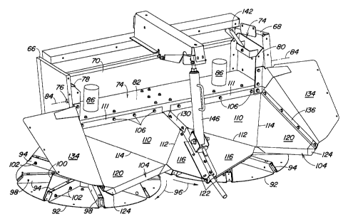
The combine structure includes two outer side panels 66 and 68 and an
upright front panel 70 joined to the combine side sheets 12 as shown in Fig.
3. A
spreader frame 74 is attached to the side panels 66, 68 at pivots 76, one at
each
side of the spreader. The frame 74 includes two inner side panels 78 and 80
and a
lower panel 82. The two pivots 76 couple the inner panels of the frame 74 to
the
outer side panels 66, 68 and define a transverse pivot axis 84.
Hydraulic motors 86 are mounted to the frame lower panel 82. Each motor
has an output shaft 90 that extends downward from the motor below the lower
panel
82. A disk 92 is coupled to each output shaft 90 for rotation therewith. The
disks 92
are formed with raised radial ribs 94. The disks 92 counter-rotate as shown by
the
3
CA 02298988 2000-02-18
arrows 96 in Figure 2. Optional blades 100 may be mounted to the radial ribs
94 with
fasteners 102 extending through the apertures 98 in the ribs. The blades may
be
mounted on some or all of the ribs 94, as long as the disk remains balanced.
The
crop residue exiting the combine through the opening 60 is engaged by the ribs
and
blades of the rotating disks 92 to propel the residue over a wide width behind
the
combine. The blades function as a fan to draw air from the combine and create
airflow to the rear and to the side to assist in the dispersal of the residue.
Shrouding is provided over and around the disks 92 to help direct the crop
residue as it is distributed. The shrouding includes a top shroud 104 over
each of the
disks 92, rearward of the shafts 90. Each top shroud 104 is coupled to the
lower
panel 82 by a plurality of nut and bolt fasteners 106. The top shrouds 104 are
generally formed of three sections, a shroud center section 110, a shroud
inner
section 116 and a shroud outer section 120. The three sections are all
generally
triangular in shape. The top shrouds 104 are preferably each formed as a
single
piece of stamped sheet metal having a fold 112 between the center section 110
and
the inner section 116 and a fold 114 between the center section 110 and the
outer
section 120. The sections could be made as separate components bolted
together.
The shroud center section 110 has a front edge 111 that is fastened to the
lower
panel 82.
The three shroud sections slope downwardly from the front edge 111. The
inner sections 116 also slope toward an inner lower corner 122 while the outer
sections 120 slope toward outer lower corners 124. The inner sections 116 and
the
outer sections 120 have a greater downward slope than does the center section
110.
The inner lower corners 122 are slightly lower than the outer lower corners
124.
A divider 130 between the two top shrouds 104 extends downwardly from the
center and inner shroud sections 110, 116 toward the disks 92 as best seen in
Figure 4. The divider 130 serves to separate the flow of the crop residue
between
the two disks 92.
Side shrouds 134 are fastened along outer edges 136 of the top shrouds 104.
The side shrouds 134 first extend upward and then project outward from the
outer
edges 136. Additional front shrouds 140 (Fig. 3) are provided forward of the
side
4
CA 02298988 2000-02-18
shrouds 134. The front shrouds 140 are fastened to the combine side sheets and
extend outwardly beyond the side sheets. A skirt 138 may be added to and
depend
from the front shrouds 140. The top shrouds 104, side shrouds 134 and front
shrouds 140 operate to keep the residue from being dispersed upward.
A bottom panel 154, Figure 3, extends downward at the rear of the cleaning
system 40, in front of the disks 92. The bottom panel has an upper metal
portion 156
and a lower depending skirt 158. The skirt gives the panel flexibility in
accessing
areas of the combine in front of the panel. The bottom panel 154 helps to
prevent
forward dispersal of the crop residue.
The spreader frame 74 has a spreading position shown in Figures 1-3 in
which the shafts 90 are oriented generally vertically and the disks generally
horizontally. This is an operative spreading position in which crop residue
from the
combine is received by the disks 92 and distributed thereby. In this position,
the
shrouding around the disks and the bottom panel 154 of the combine behind the
cleaner 40 enable the rotating disks 92 to draw air from the combine cleaning
system
40.
The frame 74 is rotatable about the pivot axis 84 to a rearwardly raised
position shown in Figure 3. This is a windrowing position in which the disks
92 are
not rotated. The crop residue is allowed to fall from the combine through the
opening
60 directly to the ground, without being dispersed over a wide area. This
leaves the
residue in a windrow for subsequent collection. Gas assist cylinders 142 are
provided at each side of the spreader to facilitate lifting of the spreader to
the
windrowing position. The cylinders 142 extend between the frame 74 and the
panel
70 of the combine structure. The gas assist cylinders provide a biasing force
on the
frame 74 to urge the frame to the windrowing position. Other biasing
mechanisms
may be used such as a spring. Furthermore, a powered lift mechanism such as a
hydraulic cylinder or a motor driven lift linkage may also be used.
A hold down latch 146 extends between the combine frame above the
spreader and the top shrouds 104. The hold down latch retains the spreader in
the
spreading position in opposition to the gas assist cylinders 142. The hold
down latch
146 is manually released to enable the spreader to rotate to the windrowing
position.
5
CA 02298988 2000-02-18
An upper latch 150 (Fig. 3) on the combine frame insures that the spreader
remains in the windrowing position and that the weight of the spreader and
vibration
forces are not resisted solely by the gas assist cylinders 142. The upper
latch 150
couples to a striker bar 152 on the hold down latch 146 to retain the frame 74
in the
windrowing position. The latch 150 is manually released to lower the spreader
to the
spreading position. Once released, the operator manually pushes down on the
top
shrouds 104, in opposition to the gas assist cylinders 142, to return the
spreader to
the spreading position. The hold down latch 146 is then manually engaged to
retain
the spreader in the spreading position. One person can easily reposition the
spreader from the spreading position to the windrowing position or vice versa
in a
matter of seconds.
The spreader of the present invention functions to effectively and evenly
spread crop residue over a wide area at the rear of the combine. In addition,
the
spreader can easily be moved to a windrowing position without entirely
removing the
spreader from the combine. This avoids the difficult and time consuming
process
often required when it is desired to windrow the crop residue.
While the spreader has been shown and described as having a pair of disks,
the invention can be used with a single disk. The invention should not be
limited to
the above-described embodiment, but should be limited solely by the claims
that
follow.
6